Evaluation and Repair of Wrought Iron and - Purdue e-Pubs ...
Evaluation and Repair of Wrought Iron and - Purdue e-Pubs ...
Evaluation and Repair of Wrought Iron and - Purdue e-Pubs ...
Create successful ePaper yourself
Turn your PDF publications into a flip-book with our unique Google optimized e-Paper software.
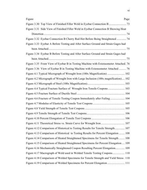
xiFigurePageFigure 3.30 Top View <strong>of</strong> Finished Filler Weld in Eyebar Connection B........................ 73Figure 3.31 Side View <strong>of</strong> Finished Filler Weld in Eyebar Connection B Showing HeatDistortion .................................................................................................................. 74Figure 3.32 Eyebar Connection B Cherry Red Hot Before Being Straightened ............. 74Figure 3.33 Eyebar A Before Testing <strong>and</strong> After Surface Ground <strong>and</strong> Strain Gages hadbeen Attached............................................................................................................ 75Figure 3.34 Eyebar B Before Testing <strong>and</strong> After Surface Ground <strong>and</strong> Strain Gages hadbeen Attached............................................................................................................ 75Figure 3.35 Front View <strong>of</strong> Eyebar B in Testing Machine with Extensometer Attached. 76Figure 3.36 View <strong>of</strong> Eyebar B in Testing Machine with Extensometer Attached .......... 76Figure 4.1 Typical Micrograph <strong>of</strong> <strong>Wrought</strong> <strong>Iron</strong> (100x Magnification) ........................ 102Figure 4.2 Micrograph <strong>of</strong> <strong>Wrought</strong> <strong>Iron</strong> with Large Inclusion (100x magnification).... 102Figure 4.3 Micrograph <strong>of</strong> Steel (100x Magnification).................................................... 103Figure 4.4 Typical Fracture Surface <strong>of</strong> <strong>Wrought</strong> <strong>Iron</strong> Tensile Coupons ....................... 103Figure 4.5 Fracture Surface <strong>of</strong> Ductile Steel .................................................................. 104Figure 4.6 Fracture <strong>of</strong> Tensile Testing Coupon Immediately after Failing .................... 104Figure 4.7 Modulus <strong>of</strong> Elasticity <strong>of</strong> Tensile Test Coupons ............................................ 105Figure 4.8 Yield Strength <strong>of</strong> Tensile Test Coupons ....................................................... 105Figure 4.9 Tensile Strength <strong>of</strong> Tensile Test Coupons..................................................... 106Figure 4.10 Percent Elongation <strong>of</strong> Tensile Test Coupons .............................................. 106Figure 4.11 Theoretical Stress vs. Strain Curve for <strong>Wrought</strong> <strong>Iron</strong>................................. 107Figure 4.12 Comparison <strong>of</strong> Historical to Testing Results for Tensile Strength.............. 107Figure 4.13 Comparison <strong>of</strong> Historical to Testing Results for Percent Elongation ........ 108Figure 4.14 Comparison <strong>of</strong> Heated Straightened Specimens for Tensile Strength ........ 108Figure 4.15 Comparison <strong>of</strong> Heated Straightened Specimens for Percent Elongation .... 109Figure 4.16 Mechanically Straightened Coupon Resulting Percent Elongation............. 109Figure 4.17 Macrograph <strong>of</strong> Weld used in Welded Tensile Testing Coupons................. 110Figure 4.18 Comparison <strong>of</strong> Welded Specimens for Tensile Strength <strong>and</strong> Yield Stress . 110Figure 4.19 Comparison <strong>of</strong> Welded Specimens for Percent Elongation ........................ 111


