DSP Speaker, QST November 11 - KG4JJH
DSP Speaker, QST November 11 - KG4JJH
DSP Speaker, QST November 11 - KG4JJH
- No tags were found...

You also want an ePaper? Increase the reach of your titles
YUMPU automatically turns print PDFs into web optimized ePapers that Google loves.
<strong>DSP</strong> <strong>Speaker</strong>Build this noise reducing system to enhance your station’s audioAdaptive filters using Digital Signal Processing can be very effective in improving thevoice quality of amateur radio communications. <strong>DSP</strong> analyzes the signal anddifferentiates the noise from the speech. Unwanted noise and interference is thenattenuated to leave only the speech. The signal is constantly monitored and the <strong>DSP</strong>automatically adapts to any changes in the signal conditions.BHI Ltd 1 has a line of <strong>DSP</strong> products aimed at the amateur radio community. A popularradio modification is to add the NE<strong>DSP</strong>1061-KBD module inside the radio 2 . It adds amicroprocessor and LED to the basic module with a pushbutton that steps through fourlevels of noise reduction. To take advantage of noise reduction on multiple radios thisproject uses the basic NE<strong>DSP</strong>1061-PCB module and offers eight levels of noisereduction. Audio from the radio is fed to a level attenuator, clipping indicator, <strong>DSP</strong>module, and a power amplifier that drives a speaker and headphones.Circuit DescriptionToggle switch S3 powers the unit and turns on the yellow PWR LED. <strong>Speaker</strong> andheadphone levels are controlled by VOLUME potentiometer R17. The <strong>DSP</strong> LEVEL isselected by rotary switch S1. Toggle switches S2 and S4 switch the <strong>DSP</strong> in and out andturn the speaker on and off, respectively. The rear panel contains INPUT jack J1,PHONES jack J2, and 12VDC power jack J3. Board mounted jumper JP1 allows the useof stereo headphones by connecting the output to both channels. Ferrite beads are used onall signals entering and exiting the circuit.M1, NE<strong>DSP</strong>1061-PCBThis tiny noise reduction module measures 1.45” x 1.06” and has 10 input/output pins. Ithas an internal voltage regulator allowing it to operate over a 5-15 VDC range. The eightavailable <strong>DSP</strong> levels correspond to 9-35 dB of white noise reduction (hiss), and 4-65 dBof tone reduction (heterodynes). Pins 1-3 have internal pull-up resistors to 3.3VDC anddetermine the <strong>DSP</strong> level according to Table 1.<strong>DSP</strong> <strong>Speaker</strong>, <strong>KG4JJH</strong>
NE<strong>DSP</strong>1061-PCB <strong>DSP</strong> Level Setting<strong>DSP</strong> Tone White Noise Pin 3-N2 Pin 2-N1 Pin 1-N0Level Reduction Reduction (VDC) (VDC) (VDC)BCD1 4 dB 9 dB 0 0 0 02 5 dB <strong>11</strong> dB 0 0 3.3 13 6 dB 13 dB 0 3.3 0 24 8 dB 15 dB 0 3.3 3.3 35 16 dB 17 dB 3.3 0 0 46 21 dB 20 dB 3.3 0 3.3 57 25 dB 24 dB 3.3 3.3 0 68 65 dB 35 dB 3.3 3.3 3.3 7Table 1The N0, N1, and N2 voltage levels correspond to BCD numbers 0-7 and wouldpreferably be set with an eight position BCD complement switch. However, panelmounted BCD switches are not readily available, so the <strong>DSP</strong> level is set with a SP8Trotary switch and diodes D1-D12. Resistors R6 and R7 form a -10 dB attenuation pad toreduce speaker level to line level.The noise cancellation can be turned off by grounding pin eight. However, this methodresults in a loss of high frequencies, so toggle switch S4 switches between the input andthe module output.U1, TL062 Dual Op AmpThe M1 module requires input levels greater than 50 mV RMS, with a nominal level of300 mV RMS. The maximum input level is not specified but appears to be around 350mV RMS. The module includes a surface mounted LED to indicate clipping levels butthe LED is very small and not amenable to panel mounting. Therefore, a simple CLIPindictor has been added. U1 forms a window comparator to detect the positive andnegative peaks of the audio input. The op amp outputs are mixed by diodes D13 and D14,smoothed by C6, R5 and R14, and feed the LED driver Q1 with a positive pulse. C10adds a small output delay in order to allow detection of very short peaks 3 .U2, Audio Amplifier, TDA7240AVWhen supplied with 12VDC, this amplifier will deliver approximately 8 watts RMS intoan 8Ω load at 0.5% THD. This is more than enough power to cleanly drive mostspeakers. U2 has one input and a differential output, so neither side of the bridgedspeaker output is grounded. The headphone output utilizes one side of the amplifieroutput referenced to ground. Do not omit coupling capacitor C8 as the amplifier will notwork without it.SP1, <strong>Speaker</strong>, HiVi B3NThis full range shielded speaker has a frequency response of 80-8,000Hz and a fairlysmooth response curve. The speaker was selected to cover the voice frequency spectrumwithout adding too much bass. Although the speaker sensitivity level (SPL) is low at 81<strong>DSP</strong> <strong>Speaker</strong>, <strong>KG4JJH</strong> 2 of 5
dB the U2 amplifier has enough reserve power to overcome this deficiency. A speakergrill is recommended for those who are concerned about the unprotected speaker conegetting damaged. Commercially available grills are either too large for the enclosure orhave mounting holes that interfere with the speaker frame. A substitute speaker grill canbe fashioned from a fan guard which is mounted on ¼-inch standoffs in front of thespeaker.ConstructionThe prototype was built using perf-board construction and point to point wiring. Keepinputs away from outputs and be sure to ground the enclosure. For non-metallicenclosures, shielded cable is recommended on all audio lines. To prevent unwantedrattles, put a small dab of silicon sealant on the ferrite beads.10-pin and 5-pin headers are soldered to the M1 module which is then plugged into boardmounted sockets. The 5-pin header/socket helps to mechanically secure the module to theboard and has no pin connections. For ease of assembly, components mounted off of theboard are connected via male headers and female header plugs. The LED rear mountingnut can be threaded over the 2-pin header connector. First, knock the edges off of theconnector with a small file and then cut threads by screwing the nut over the connector.Sealed speaker enclosures should be airtight to prevent unwanted air leaks. Small gapscan cause air noises and unload the speaker. For this reason, the front and rear panelcontrols and jacks are threaded and sealed with a nut. There is still some air leakage but itis not objectionable in this frequency limited application. The enclosure features a frontpanel gasket which reduces air leakage and prevents rattles. The enclosure walls are linedwith ½” adhesive-backed acoustic foam to absorb internal standing waves and preventreflections to the speaker cone. Keep the foam away from the heat sink to prevent it frommelting. Before mounting the speaker, install the supplied adhesive backed gasketmaterial around the speaker cutout and install the speaker from the outside of theenclosure using 6-32 x ½-inch screws.If the front and rear panel components are mounted on the perf-board according to thedrawing, then the drilling template can be used to mark the holes. Print the full-sizedrilling template and then measure the panel and mark horizontal and vertical centerlines.Align the template with the panel centerlines and fasten it to the panel using a glue stickor rubber cement. Next, center-punch and drill all holes. The 2-7/8” diameter speakercutout was made with a metal hole saw. Alternatively, small holes can be drilled aroundthe circumference of the hole to remove the bulk of the material and then filed smooth.Labeling can be added using dry transfer letters or a labeling machine. I used white drytransfer lettering (Woodland Scenics Railroad Gothic DT507) from the railroad section ofmy local hobby shop. A method for applying dry transfer letters is to print the letteringtemplate full size on clear film. Secure the panel to a table top and then center and tapethe clear film over the panel. Place the dry transfer sheet under the clear film, line up theappropriate letter, and then burnish. Follow up with a couple of coats of clear mattlacquer to protect the lettering. Be sure to test the lacquer on a test piece to ensurecompatibility.<strong>DSP</strong> <strong>Speaker</strong>, <strong>KG4JJH</strong> 3 of 5
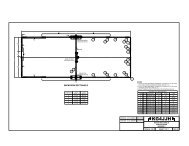
SetupConnect 12VDC from the radio power supply to a 2.5mm x 5.5mm plug (center positive)to power the unit. The <strong>DSP</strong> <strong>Speaker</strong> can draw over one amp at high volumes so makesure the power supply is adequate. Connect the speaker/headphone output from the radioto the INPUT jack using a shielded cable with a 3.5mm mono phone plug on one end anda suitable plug on the radio end. The Yaesu FT-817/857 radios have a slide switch thatswitches the audio output to speaker or headphone levels but there is little differenceobserved between the two settings.The M1 module has onboard input and output trimpots for setting sensitivity levels. Setthese input and output trimpots to midpoint. The trimpots don’t have stops so there willbe a dead band area where the sound disappears. Referring to Figure 1, the trimpotsettings are indicated by a small circle in front of the screwdriver slot and are shown atmidpoint. The <strong>DSP</strong> level is set by rotary switch S1 so remove the shorting blocks onheaders JP1, JP2, and JP3.Figure 1The CLIP detector is adjusted with the <strong>DSP</strong> <strong>Speaker</strong> connected to the radio. Tune in to astrong station and adjust the radio volume until you see the M1 overload LED light on thepeaks. Adjust trimpot R16 until the CLIP LED turns on, mimicking the M1 LED.OperationOperation couldn’t be simpler. At first, set your radio receiver for full bandwidth anddisable any built-in noise reduction. Start with low <strong>DSP</strong> levels and increase the level asband conditions warrant. At the higher <strong>DSP</strong> levels the audio is somewhat “watery”sounding but still readable. The <strong>DSP</strong> is compatible with all modes of operation but ismost remarkable on SSB. Heterodynes, static, hiss, buzzing, and other noises can beattenuated to a remarkable degree. The included audio files were made with a <strong>DSP</strong>setting of 5.Like all <strong>DSP</strong> processors, there is a time delay associated with the reduction of noise. Thetime required to analyze the signal and respond appears to be less than a second for theBHI <strong>DSP</strong> unit and is the same for all levels of <strong>DSP</strong>.<strong>DSP</strong> <strong>Speaker</strong>, <strong>KG4JJH</strong> 4 of 5
Yaesu FT-817/857 radios will begin to light the CLIP LED with the volume control at the12 o’clock position. For other radios, increase the radio volume until the CLIP LEDlights and then back off slightly. The <strong>DSP</strong> <strong>Speaker</strong> volume is set to the 9 or 10 o’clockposition for normal listening. I find that the extra audio power comes in handy when I amaway from the radio, manually turning a beam while listening for peak reception. I amlooking forward to the next VHF contest to put the <strong>DSP</strong> <strong>Speaker</strong> to good use. Six meterband noise at our contest location gets old after only a few hours of operation.ConclusionThe <strong>DSP</strong> <strong>Speaker</strong> is a versatile tool that will clean up received audio and significantlyimprove intelligibility. The aluminum enclosure has a small footprint (6-3/4”H x 4-3/4”W x 4”D) and can be used with any radio with a speaker or headphone output. Ahighly effective noise reduction module teamed up with a hefty power amplifier andquality speaker form an impressive audio system for your radio. The end result is lesslistener fatigue, so clean up the noise pollution and get more enjoyment out of your radio!Allen Baker, <strong>KG4JJH</strong>2<strong>11</strong> Brochardt Blvd.Knoxville, TN 37934kg4jjh@arrl.nethttp://www.kg4jjh.com/Attachmentso Schematico Bill of Materialso Assembly Drawings & Templateso Pictureso Audio FilesNotes1. BHI Ltd, PO Box 318, Burgess Hill, West Sussex, RH15 9NR, UK,http://www.bhi-ltd.com/2. BHI <strong>DSP</strong> Noise Reduction Module for Yaesu FT-817, Chris Lorek, G4HCL,http://www.wimo.de/download/bhi_rdcom_nedsp1061_review-dec03.pdf3. Audio Clipping Indicator, http://www.redcircuits.com/Page132.htm<strong>DSP</strong> <strong>Speaker</strong>, <strong>KG4JJH</strong> 5 of 5