Download Nuflo Pressure Relief Valve ... - Proflow Systems
Download Nuflo Pressure Relief Valve ... - Proflow Systems Download Nuflo Pressure Relief Valve ... - Proflow Systems
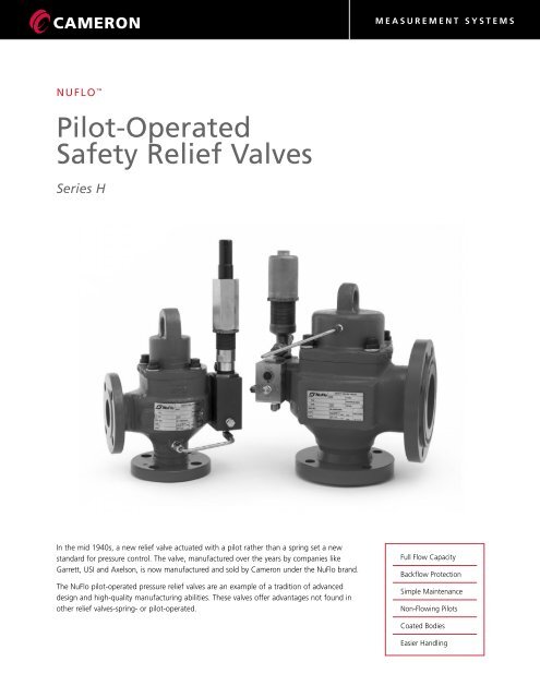
MEASUREMENT SYSTEMSNUFLO Pilot-OperatedSafety Relief ValvesSeries HIn the mid 1940s, a new relief valve actuated with a pilot rather than a spring set a newstandard for pressure control. The valve, manufactured over the years by companies likeGarrett, USI and Axelson, is now manufactured and sold by Cameron under the NuFlo brand.The NuFlo pilot-operated pressure relief valves are an example of a tradition of advanceddesign and high-quality manufacturing abilities. These valves offer advantages not found inother relief valves-spring- or pilot-operated.Full Flow CapacityBackflow ProtectionSimple MaintenanceNon-Flowing PilotsCoated BodiesEasier Handling
- Page 2 and 3: Valve TypesType HFThis is a full li
- Page 4 and 5: Operation Type HFRelief Valve Close
- Page 6 and 7: In-Service Testing and Pilot-Settin
- Page 8 and 9: Installation SchematicsTypes HFType
- Page 10 and 11: Soft Seat ServiceMaterial Continuou
- Page 12: MEASUREMENT SYSTEMSXylan® is a reg
MEASUREMENT SYSTEMSNUFLO Pilot-OperatedSafety <strong>Relief</strong> <strong>Valve</strong>sSeries HIn the mid 1940s, a new relief valve actuated with a pilot rather than a spring set a newstandard for pressure control. The valve, manufactured over the years by companies likeGarrett, USI and Axelson, is now manufactured and sold by Cameron under the NuFlo brand.The NuFlo pilot-operated pressure relief valves are an example of a tradition of advanceddesign and high-quality manufacturing abilities. These valves offer advantages not found inother relief valves-spring- or pilot-operated.Full Flow CapacityBackflow ProtectionSimple MaintenanceNon-Flowing PilotsCoated BodiesEasier Handling
<strong>Valve</strong> TypesType HFThis is a full lift, pop-action valve with a fixed (5% to 7%)blowdown using a single non-flowing pilot. This type of valveis designed for gas and/or vapor service and is offered in sizesof 1" through 8" with operating pressures ranging from20 psig to 6000 psig.Type HLThis is a modulating valve with a fixed (3% to 5%) blowdownusing a single non-flowing pilot. This valve is designed forgas, vapor and/or liquid service and is offered in sizes of1" through 8" with operating pressures ranging from 15 psigto 1500 psig.AdvantagesFull Flow CapacityIn addition to the various API orifice sizes, Cameron offersvalves with non-standard API orifice sizes for maximum flowcapacity and smoother operation. Many times this allows forthe use of smaller size valves at a cost savings to the customer.Backflow ProtectionThe unique NuFlo split piston (optional) is designed toeliminate the effect of pressure in the discharge system backflowinginto a relief valve on installations where several valvesdischarge into a common manifold.Simple MaintenanceAll maintenance, including changing the valve seat, can beperformed using ordinary hand tools without removing thevalve from the installation.Non-Flowing PilotsNuFlo non-flowing pilots reduce the problems of “freeze-up”caused by the pressure drop through the flowing-type pilots.Coated BodiesThe bodies and piston housings of all NuFlo pilot-operatedsafety relief valves are internally and externally coated withXylan® for corrosion protection and lubricity.Easier HandlingA lifting eye is conveniently located on the center of the valvefor ease of handling during installation or removal.FeaturesSoft or Hard Seat SealsSoft or hard seat seals are available for a variety of serviceconditions and applications. Soft seat seals are recommendedfor discharge set pressures of 25 psi to 1500 psi. Hard seatseals are recommended for discharge set pressures above1500 psi.Variable Flange DimensionsFlange dimensions can be modified on special order to fit mostexisting installations. This permits NuFlo pilot-operated safetyrelief valves to be used as replacements for older spring-loadedvalves which may not conform to new safety standards.In-Service Test KitThis optional feature allows checking or changing the pilot setpressure in the field with the valve in service.Manual BlowdownThis optional device, which allows manual blowdown of thesystem, can also be controlled from a remote location.Direct or Remote ControlDepending on the application, the operation of the NuFlopilot-operated safety relief valve may be controlled directlyfrom the point of installation or remotely.No “Simmer”NuFlo pilot-operated safety relief valves are designed toeliminate "simmer" at the valve seat. They do not require"percent accumulation" or over-pressure to operate.Special FlangesNuFlo pilot-operated safety relief valves can be supplied withspecial flanges such as Graylock, Taper-Lok, Lenz, etc.2
MEASUREMENT SYSTEMSAdvantages and FeaturesEasy and economical to maintainAll maintenance can be performed without removing valve from lineReplaceable soft seatSaves costly lapping of valve seatOperates without simmer at valve seatCan be set close to system operating pressure. Unaffected by vibration of pulsationBlock and bleed pilot as standardReduces freeze-ups caused by pressure drop through flowing type pilotsAccurate setting with small volume of pressureTest fixture available for fast accurate settingBackflow protectionPrevents flow of gas back through valve when working on lineCombines functions of blowdown and safety valvesSaves cost of additional valves and pipingNuFlo Pilot Operated Competitive SpringHF HL Loaded <strong>Valve</strong>Yes Yes NoYes Yes YesYes Yes NoYes Yes NoYes Yes NoYes Yes NoYes Yes NoHigher capacity per valve size Yes Yes NoField test of pilot set pressureSet pressure can be checked or changed with valve still in serviceNo Yes NoCan be used with solenoid valveFor electric or pneumatic interfaceYes Yes NoCoated internally and externallyBodies and piston housings. Xylan coated for corrosion protection and lubricityYes Yes NoBalanced pilotAllows venting into discharge system without effect of back pressureNo Yes NoApplicationA pilot-operated pressure relief valve, according to the 1992ASME Code Section VIII, Division 1, Section UG-126, is apressure relief valve in which the major relieving device iscombined with, and is controlled by, a self-actuated auxiliarypressure relief valve. NuFlo pilot-operated pressure relief valvesare designed to be used wherever there is a need to exhaustthe overpressure volume of gas, vapor and/or liquid.Applications include oil and gas production systems,compressor stations, gas transmission (pipelines) facilities,storage systems, distribution systems and in all types ofprocessing plants.<strong>Valve</strong> OperationNuFlo pilot-operated safety relief valves operate on theprinciple of unequal areas exposed to the same pressure.When the relief valve is closed, system pressure pushesupwards against the piston seat seal on an area equal to theinside diameter of the seat. Simultaneously, the same systempressure passes through the pilot, exerting a downward forceon the piston acting on an area approximately 50% greaterthan the inside diameter of the seat. The resulting differentialforce holds the valve tightly closed. As the system pressurerises, the force against the piston seal increases.Then, when the system pressure reaches the relief valvedischarge set pressure, the pilot cuts off system pressure andopens the top of the piston to vent pressure. As the pressureabove the piston is relieved, the relief valve opens, dischargingline pressure.When the predetermined blowdown pressure is reached,the pilot shuts off the exhaust and re-opens the flow ofsystem pressure to the top of the piston, effectively closingthe relief valve.3
Operation Type HF<strong>Relief</strong> <strong>Valve</strong> ClosedAt below “set point”, the normally opencombination pilot allows system pressure toenter the piston housing cavity of the reliefvalve on top of the free-floating piston. The topof the relief valve piston has a larger area thanthe valve seat where the piston seals. Equalpressure at both ends of the piston creates adifferential downward force, which holds thepiston tightly closed on the valve seat.Type HF <strong>Relief</strong> <strong>Valve</strong>(Fixed Blowdown 5-7%)Below: Type HF relief valve (closed position)<strong>Relief</strong> <strong>Valve</strong> OpenWhen system pressure reaches the set point,the pilot piston is lifted off the valve seat. Theblowdown seat seals off incoming line pressure,causing the exhaust port to open and bleedpressure from the relief valve piston cavity.Decreasing pressure on the top of the reliefvalve piston allows the valve to open, relievingsystem overpressure. As system pressure dropsbelow the blowdown reset point, theblowdown seat opens, reseating the pilotpiston, which causes the exhaust port to close.System pressure re-enters the relief valve pistoncavity, closing the relief valve.Right: Type HF relief valve (relieving position)4
MEASUREMENT SYSTEMSOperation Type HL<strong>Relief</strong> <strong>Valve</strong> ClosedAt below “set point,” the normally open TypeHL pilot allows system pressure to enter thepiston housing cavity of the relief valve on topof the free-floating piston. The top of the reliefvalve piston has a larger area than the valveseat where the piston seals. Equal pressure atboth ends of the piston creates a differentialdownward force, which holds the piston tightlyclosed on the valve seat.Type HL <strong>Relief</strong> <strong>Valve</strong>Below: Type HL relief valve (closed position)<strong>Relief</strong> <strong>Valve</strong> OpenWhen system pressure reaches the set point, thepilot piston forces the pilot stem upward bycompressing the pilot valve spring. Thismovement of the stem simultaneously blocksthe system pressure passageway through thepilot and commences the bleeding of pressurefrom the relief valve piston housing cavity.Decreasing pressure on the top of the reliefvalve piston allows system allows the valve toopen, relieving system overpressure. As systempressure drops below the blowdown resetpoint, system pressure re-enters the relief valvepiston cavity, closing the relief valve.Right: Type HL relief valve (relieving position)5
In-Service Testing and Pilot-Setting OptionsAll NuFlo pilot-operated pressure relief valves may be orderedwith an In-Service Test Kit. The procedures for the use of thisIn-Service Kit are shown below.Type HFIn-Service Testing of Pilot Set <strong>Pressure</strong>CAUTION: Never use oxygen as a pressure source.<strong>Pressure</strong> from a cylinder of nitrogen or some other pressuresource (NOT OXYGEN) may be used to check the setting or toreset the pressure at which the relief valve will operate.1. Connect pressure hose from nitrogen bottle to field testvalve "A".2. Close vent valve "B".3. Open field test valve "A".4. Slowly open block valve "C" permitting test pressure toincrease to valve set point.5. Observe set pressure on test gauge and record.6. Close valves "A" and "C".7. Open vent valve "B".8. Disconnect pressure hose from field test valve "A".NOTE: For additional information on In-Service testing, referto the service manual or technical data sheets for thisproduct.When a relief valve is not equipped with the In-Service Test Kit,a <strong>Relief</strong> and Blowdown test fixture can be used to check orchange valve set and blowdown pressures in field shops. Onlythe pilots need to be removed from the relief valve and it isnot necessary to remove the valve itself from the installation.The operation of this portable test fixture is simple andconvenient.CAUTION: Never use oxygen as a pressure source.<strong>Pressure</strong> from a cylinder of nitrogen or some other pressuresource (NOT OXYGEN) may be used to check the setting or toreset the pressure at which the relief valve will operate.Special training is not requiredand complete instructions arefurnished with each fixture.The test fixture may be orderedwith optional needle valves andadapters for any type of pilot.Type HLTypical Direct Hook-Up with In-Service Test <strong>Valve</strong>(Gas Service Only)1. Connect pressure hose from nitrogen bottle or hydraulichand pump to test port of header block.2. Close vent valve "A".3. Slowly open block valve "B", or operate hydraulic handpump, permitting test pressure to increase to valve set point.4. Observe set pressure on test gauge and record.5. Close valve "B", or release pressure on hand pump.6. Open vent valve "A".7. Disconnect pressure hose from test port.NOTE: For additional information on In-Service testing, refer tothe service manual or technical data sheets for this product.6
MEASUREMENT SYSTEMSPilot ConstructionThe Type HF pilot is a single combination control with a fixedblowdown for controlling relief valve opening and closingpressure set points. The opening set pressure is determined bythe force of a control spring, which holds the relief controlsection of the valve closed. When system pressure acting onthe relief control valve seat area equals the spring force, therelief control opens, and the blowdown control section closes,blocking system pressure from passing into the chamber abovethe main valve piston. As the relief control opens, the pressureunderneath the control seat is exposed to a larger pressurearea which provides “snap” action of the control pilot toquickly reduce pressurein the piston dome.This pressure reductioncauses the main valvepiston to lift, relievingsystem pressure.After the systempressure is reduced toa point whereby thecontrol valve springforces the blowdowncontrol ball to unseat,the relief control valvecloses, and the openblowdown control valveallows system pressureto re-enter the pistondome, forcing the mainpiston down to a closedvalve position.The Type HL pilot is a single-control pilot with a fixedblowdown for controlling the opening and closing of the reliefvalve. Opening and closing pressures are determined by theforce of a pilot control spring. System pressure is applied tothe pilot control piston and also to the pilot inlet "Hi" port.The lifting force produced by the pressure on the controlpiston is reacted by the opposing force of the pilot spring.When the spring force is greater than the pressure force of thecontrol piston, system pressure is communicated through theinlet "Hi" port of the pilot to the top of the relief valve piston.Since the area on top of the relief valve piston is greater thanthe seat area, the valve is held in the closed position. Aspressure increases above the set point, the force of the controlpiston becomes greater than the reacting spring force. Thisunbalanced condition shifts the pilot stem upward, blockingthe pressure coming into the inlet “Hi” port and allowing thepressure above the reliefvalve piston to bleed off.As the pressure force,(which holds the pistonon the seat) decreases,the relief valve opens.If system pressurecontinues to rise, thepiston lifts fully andremains open untilsystem pressure isreduced sufficientlyfor the pilot spring toshift the pilot into itsflowing position.Function of the Split PistonNormal Piston PositionAll NuFlo pilot-operatedpressure relief valves canbe ordered with theexclusive NuFlo splitpiston. This piston isdesigned to eliminate theeffect of back-pressureimposed on the dischargeside of the valve.Split Piston SeparatedThe split piston isrecommended forinstallations where a manifolddischarge system serves anumber of relief valves. If amanifolded relief valve is outof service when one or moreother valves exhausts into thecommon discharge system,the split piston separates andprevents backflow throughthe out-of-service valve.7
Installation SchematicsTypes HFType HLDirect Hookup<strong>Relief</strong> valves configured fordirect operation are equippedwith an internal pressurepickup tube (stinger) in thethroat of the valve inlet. Theyare factory shipped as selfcontainedassemblies, readyfor installation.Remote Hookup<strong>Relief</strong> valves configured forremote operation do notcontain an integral pressurepickup connection. <strong>Pressure</strong>is sensed from a remotepoint on the vessel/processline through a single tubeconnected to the header blocklocated on the valve.8
MEASUREMENT SYSTEMSOrifice SelectionAvailable Orifice Sizes for Type HF and HL Pilot-Operated <strong>Relief</strong> <strong>Valve</strong>s<strong>Valve</strong> Coefficient: 0.859 (gas), 0.674 (liquid)<strong>Valve</strong> Size Outlet Orifice Orifice Area (Sq. In.)1” x 2” Single D 0.110E 0.196F 0.307G 0.503GX 0.6521” 0.7851-1/2" x 2" Single D 0.110E 0.196F 0.307G 0.503H 0.785J 1.287JX 1.6331-1/2” 1.7671-1/2" x 3" Single G 0.503H 0.785J 1.287JX 1.6331-1/2” 1.7672" x 3" Single G 0.503H 0.785J 1.287JX 1.633K 1.838KX 2.7762” 3.141<strong>Valve</strong> Size Outlet Orifice Orifice Area (Sq. In.)3” x 4” Single J 1.287K 1.838L 2.853M 3.600N 4.340P 6.3803” 7.0684” x 6" Single/Dual L 2.853M 3.600N 4.340P 6.3804” 12.5666” x 8" Single/Dual Q 11.045R 16.000T 26.0006” 28.2708” x 8" Dual Q 11.045R 16.000T 26.0007” 38.4847-1/2” 44.1788” x 10" Single/Dual Q 11.045R 16.000T 26.0007” 38.4847-1/2” 44.178Trims AvailableMaterials of Construction Standard Stainless Steel Full Stainless Steel NACEHF HL HF HL HF HL HF HLBody CS (1) CS (1) CS (1) CS (1) SS (2) SS (2) CS (1)(3) CS (1)(3)Piston Housing CS (1) CS (1) CS (1) CS (1) SS (2) SS (2) CS (1)(3) CS (1)(3)Piston AL AL 316 SS 316 SS 316 SS 316 SS 316 SS 316 SS<strong>Valve</strong> Seat 316 SS 316 SS 316 SS 316 SS 316 SS 316 SS 316 SS 316 SSOrifice 316 SS 316 SS 316 SS 316 SS 316 SS 316 SS 316 SS 316 SSHeader Block CS 316 SS CS 316 SS 316 SS 316 SS CS (3) 316 SSPilot <strong>Valve</strong> 316 SS 316 SS 316 SS 316 SS 316 SS 316 SS 316 SS 316 SSNotes: (1) A-216-Gr WCB (2) A-351-Gr-CF8M (3) HRc 22 maximum9
Soft Seat ServiceMaterial Continuous Temperature, °F Minimum <strong>Pressure</strong>, psi Maximum <strong>Pressure</strong>, psiMaximum Minimum Pilot Main Pilot MainBuna-N 275 -65 15 15 6000 1500Viton 400 -65 15 15 6000 1500Teflon 400 -423 – 60 – 1500Peek 480 -423 – 1500 – 3000S.S. – – – 1500 – 6000Sizing Order FormA relief valves primary purpose is to protect lives and property. It is imperative that the propervalve be selected for your application. To assure that the proper valve is selected, please fill outthe Order or Sizing Order Form and consult your Cameron representative for assistance.GENERAL INFORMATIONCompany NameCustomer NameDateTag NumberServiceQuantityINPUT DATASpecific Gravity/Mol. WeightRatio of Specific Heats (K)Compressibility Factor (Z)Required CapacitySet <strong>Pressure</strong><strong>Relief</strong> TemperatureAllowable OverpressureBack <strong>Pressure</strong>Fluid Type & StateOPTIONSModel ■ HF (Snap Acting – 5% to 7% Fixed Blowdown) ■ HL (Modulating – 3% to 5% Fixed Blowdown)Piston Type ■ Solid ■ Split (Back Flow Preventor)Hook-up Type ■ Direct Sensing ■ Remote SensingTrim ■ Standard ■ Stainless Steel ■ NACESeal Material ■ Buna ■ Viton ■ OtherSeat Type ■ Soft ■ SS Hard ■ Peek ■ TeflonOther ■ In-service Test Kit ■ Manual Blowdown <strong>Valve</strong>■ Remote Unloader ■ Pilot Filter ■ Dome SpringMISCELLANEOUSAdditional Information10
MEASUREMENT SYSTEMS<strong>Relief</strong> <strong>Valve</strong> Order FormGENERAL INFORMATIONCompany NameCustomer NameDateTag NumberServiceQuantityISERVICE CONDITIONSSet <strong>Pressure</strong>ServiceVessel NumberFluid Type & StateVALVE SELECTIONModel ■ HF (Snap Acting – 5% to 7% Fixed Blowdown) ■ HL (Modulating – 3% to 5% Fixed Blowdown)Part NumberInlet Size & RatingOutlet Size & RatingOrificeOPTIONSPiston Type ■ Solid ■ Split (Back Flow Preventor)Hook-up Type ■ Direct Sensing ■ Remote SensingTrim ■ Standard ■ Stainless Steel ■ NACESeal Material ■ Buna ■ Viton ■ OtherSeat Type ■ Soft ■ SS Hard ■ Peek ■ TeflonOther ■ In-service Test Kit ■ Manual Blowdown <strong>Valve</strong>■ Remote Unloader ■ Pilot Filter ■ Dome SpringMISCELLANEOUSAdditional Information11
MEASUREMENT SYSTEMSXylan® is a registered trademark of Whitford CorporationMEASUREMENT SYSTEMSHOUSTONHEAD OFFICE281.582.9500NORTHAMERICA1.800.654.3760ms-us@c-a-m.comASIAPACIFIC+603.2287.1039ms-asiapacific@c-a-m.comEUROPE,MIDDLE EAST& AFRICA+44.1243.826741ms-uk@c-a-m.comUSA • CANADA • UK • SCOTLAND • CHINA • UAE • ALGERIA • MALAYSIA • INDIA • KENYA • www.c-a-m.com/floRV-RVALVE NF00033 0804


