- Page 1 and 2:
iSR6200Intelligent Storage RouterIn
- Page 3 and 4:
Table of ContentsPrefaceIntended Au
- Page 5 and 6:
iSR6200 Intelligent Storage RouterI
- Page 7 and 8:
iSR6200 Intelligent Storage RouterI
- Page 9 and 10:
iSR6200 Intelligent Storage RouterI
- Page 11 and 12:
PrefaceThis user’s guide describe
- Page 13 and 14:
PrefaceDocumentation Conventions•
- Page 15 and 16:
PrefaceCommunications StatementsFed
- Page 17 and 18:
PrefaceLaser Safety InformationVCCI
- Page 19 and 20:
PrefaceTechnical SupportContact Inf
- Page 21 and 22:
1 IntroductionThis chapter illustra
- Page 23 and 24:
1-IntroductionPower and Cooling Mod
- Page 25 and 26:
1-IntroductioniSR6200 Router Blades
- Page 27 and 28:
1-IntroductioniSR6200 Router Blades
- Page 29 and 30:
1-IntroductioniSR6200 Router Blades
- Page 31 and 32:
1-IntroductioniSR6200 Router Blades
- Page 33 and 34:
1-IntroductioniSR6200 Router Blades
- Page 35 and 36:
2 PlanningDevicesThis chapter descr
- Page 37 and 38:
2-PlanningiSCSI PerformanceBandwidt
- Page 39 and 40:
2-PlanningPerformance TuningTable 2
- Page 41 and 42:
2-PlanningHigh AvailabilityHigh Ava
- Page 43 and 44:
3 InstallationThis chapter describe
- Page 45 and 46:
3-InstallationInstalling the iSR620
- Page 47 and 48:
3-InstallationInstalling the iSR620
- Page 49 and 50:
3-InstallationInstalling the iSR620
- Page 51 and 52:
3-InstallationInstalling the iSR620
- Page 53 and 54:
3-InstallationInstalling the iSR620
- Page 55 and 56:
3-InstallationInstalling the iSR620
- Page 57 and 58:
3-InstallationInstalling New Firmwa
- Page 59 and 60:
3-InstallationInstalling New Firmwa
- Page 61 and 62:
4 ConfigurationThis chapter describ
- Page 63 and 64:
4-ConfigurationEnabling Virtual Por
- Page 65 and 66: 4-ConfigurationEnabling Virtual Por
- Page 67 and 68: 4-ConfigurationEnabling Virtual Por
- Page 69 and 70: 4-ConfigurationZoning Virtual Port
- Page 71 and 72: 4-ConfigurationZoning Virtual Port
- Page 73 and 74: 4-ConfigurationConfiguring Fibre Ch
- Page 75 and 76: 4-ConfigurationConfiguring Fibre Ch
- Page 77 and 78: 4-ConfigurationConnecting iSCSI Hos
- Page 79 and 80: 4-ConfigurationConnecting iSCSI Hos
- Page 81 and 82: 4-ConfigurationConnecting iSCSI Hos
- Page 83 and 84: 4-ConfigurationControlling per-Host
- Page 85 and 86: 4-ConfigurationControlling per-Host
- Page 87 and 88: 4-ConfigurationControlling per-Host
- Page 89 and 90: 4-ConfigurationControlling per-Host
- Page 91 and 92: 5 Fibre Channel over IPFibre Channe
- Page 93 and 94: 5-Fibre Channel over IPConfiguring
- Page 95 and 96: 5-Fibre Channel over IPConfiguring
- Page 97 and 98: 5-Fibre Channel over IPConfiguring
- Page 99 and 100: 5-Fibre Channel over IPConfiguring
- Page 101 and 102: 5-Fibre Channel over IPConfiguring
- Page 103 and 104: 5-Fibre Channel over IPConfiguring
- Page 105 and 106: 5-Fibre Channel over IPConfiguring
- Page 107 and 108: 5-Fibre Channel over IPConfiguring
- Page 109 and 110: 5-Fibre Channel over IPConfiguring
- Page 111 and 112: 6 Diagnostics andTroubleshootingDia
- Page 113 and 114: 6-Diagnostics and TroubleshootingLE
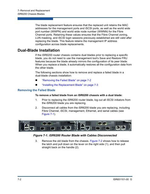
- Page 115: 7 Removal and ReplacementThis chapt
- Page 119 and 120: 7-Removal and ReplacementiSR6200 Ch
- Page 121 and 122: 7-Removal and ReplacementiSR6200 Ch
- Page 123 and 124: 7-Removal and ReplacementiSR6200 Ch
- Page 125 and 126: 7-Removal and ReplacementPower and
- Page 127 and 128: 7-Removal and ReplacementPower and
- Page 129 and 130: ATechnical SpecificationsThis appen
- Page 131 and 132: A-Technical SpecificationsiSCSI Ini
- Page 133 and 134: A-Technical SpecificationsEnvironme
- Page 135 and 136: BSimple NetworkManagement ProtocolS
- Page 137 and 138: B-Simple Network Management Protoco
- Page 139 and 140: B-Simple Network Management Protoco
- Page 141 and 142: B-Simple Network Management Protoco
- Page 143 and 144: B-Simple Network Management Protoco
- Page 145 and 146: B-Simple Network Management Protoco
- Page 147 and 148: B-Simple Network Management Protoco
- Page 149 and 150: B-Simple Network Management Protoco
- Page 151 and 152: B-Simple Network Management Protoco
- Page 153 and 154: B-Simple Network Management Protoco
- Page 155 and 156: B-Simple Network Management Protoco
- Page 157 and 158: B-Simple Network Management Protoco
- Page 159 and 160: B-Simple Network Management Protoco
- Page 161 and 162: CLog MessagesThis appendix provides
- Page 163 and 164: C-Log MessagesTable C-1. iSR6200 Ro
- Page 165 and 166: C-Log MessagesTable C-1. iSR6200 Ro
- Page 167 and 168:
C-Log MessagesTable C-1. iSR6200 Ro
- Page 169 and 170:
C-Log MessagesTable C-1. iSR6200 Ro
- Page 171 and 172:
C-Log MessagesTable C-1. iSR6200 Ro
- Page 173 and 174:
C-Log MessagesTable C-1. iSR6200 Ro
- Page 175 and 176:
C-Log MessagesTable C-1. iSR6200 Ro
- Page 177 and 178:
C-Log MessagesTable C-1. iSR6200 Ro
- Page 179 and 180:
C-Log MessagesTable C-1. iSR6200 Ro
- Page 181 and 182:
C-Log MessagesTable C-1. iSR6200 Ro
- Page 183 and 184:
C-Log MessagesTable C-1. iSR6200 Ro
- Page 185 and 186:
C-Log MessagesTable C-1. iSR6200 Ro
- Page 187 and 188:
C-Log MessagesTable C-1. iSR6200 Ro
- Page 189 and 190:
C-Log MessagesTable C-1. iSR6200 Ro
- Page 191 and 192:
C-Log MessagesTable C-1. iSR6200 Ro
- Page 193 and 194:
C-Log MessagesTable C-1. iSR6200 Ro
- Page 195 and 196:
Glossaryactivity LEDA port LED that
- Page 197 and 198:
iSR6200 Intelligent Storage RouterI
- Page 199 and 200:
iSR6200 Intelligent Storage RouterI
- Page 201 and 202:
iSR6200 Intelligent Storage RouterI
- Page 203 and 204:
iSR6200 Intelligent Storage RouterI
- Page 205 and 206:
IndexAAC power 3-7activity LEDdefin
- Page 207 and 208:
iSR6200 Intelligent Storage RouterI
- Page 209 and 210:
iSR6200 Intelligent Storage RouterI
- Page 211 and 212:
iSR6200 Intelligent Storage RouterI
- Page 213 and 214:
iSR6200 Intelligent Storage RouterI
- Page 215 and 216:
iSR6200 Intelligent Storage RouterI
- Page 218:
Corporate Headquarters QLogic Corpo