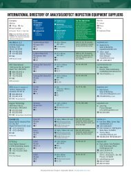
international directory of adhesive, underfill & encapsulant suppliers
international directory of adhesive, underfill & encapsulant suppliers
international directory of adhesive, underfill & encapsulant suppliers

You also want an ePaper? Increase the reach of your titles
YUMPU automatically turns print PDFs into web optimized ePapers that Google loves.
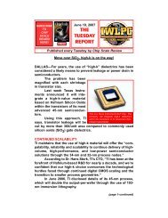
Volume 14, Number 4<br />
State-<strong>of</strong>-the-Art Thin Wafer Processing<br />
Solder Paste Properties for Die-attach Processes<br />
Ga Tech's Vision for Ultra-miniaturized Packaging<br />
Combined Clean Rooms Creates Efficiency<br />
International Directories:<br />
Automated Encapsulation Systems<br />
Adhesive, Underfill & Encapsulant Suppliers<br />
July-August July-August 2010<br />
2010
July-August 2010<br />
CONTENTS<br />
Volume 14, Number 4 The International Magazine for Device and Wafer-level Test, Assembly, and Packaging Addressing<br />
High-density Interconnection <strong>of</strong> Microelectronic IC's including 3D packages, MEMS, MOEMS, RF/<br />
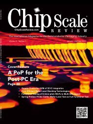
Photograph Courtesy: EV Group Europe & Asia/<br />
Pacific GmbH. Thin wafer processing is a key<br />
enabling technology for TSVs and 3D interconnects.<br />
By adding only 2 process steps, temporar y bonding<br />
and debonding, every existing fab can be upgraded<br />
for thin wafer handling capability. In the picture a<br />
process engineer in EV Group's application lab<br />
inspects a 50μm thin 300mm wafer on a film frame.<br />
Wireless, Optoelectronic and Other Wafer-fabricated Devices for the 21st Century.<br />
FEATURE ARTICLES<br />
Georgia Tech's Vision for Ultra-miniaturized Device and Systems 14<br />
Packaging Encompassing R&D, Inter-disciplinary Education and Global Collaborations<br />
Rao R. Tummala, Venky Sundaram, P. M. Raj, Raghu Pucha, Tapo<br />
Bandyopadhyay, Nitesh Kumbhat, Vivek Sridharan, Traci Walden-Monroe,<br />
Dean Sutter, Georgia Tech Microsystems Packaging Research Center<br />
State-<strong>of</strong>-the-art Thin Wafer Processing<br />
26<br />
Thorsten Matthias, Bioh Kim, Daniel Burgstaller, Markus Wimplinger,<br />
and Paul Lindner, EV Group Europe & Asia/Pacific GmbH<br />
Combining Fab and Assembly/Test Clean Rooms for Environmental 35<br />
and Operational Efficiency<br />
Edwin Feeny, Michael Piscopo, Terry Dalton, and Erwin Estepa,<br />
Texas Instruments<br />
Dispensable Solder Paste Properties for Die-attach in Power Electronics 39<br />
Albert Heilmann, WC Heraeus GmbH<br />
Chip Scale Review. July/August 2010. [ChipScaleReview.com] 1
2<br />
Chip Scale Review. July/August 2010. [ChipScaleReview.com]
Chip Scale Review. July/August 2010. [ChipScaleReview.com] 3
4<br />
Chip Scale Review. July/August 2010. [ChipScaleReview.com]
FEATURE ARTICLES<br />
Next Generation Embedded Wafer-Level BGA (eWLB) Technology<br />
Seung Wook Yoon, Yaojian Lin, STATS ChipPAC Ltd, V. P. Ganesh, A. Bahr, Infineon Technologies Asia<br />
Pacific Pte Ltd, Yonggang Jin, X. Baraton, STMicroelectronics, Pandi Chelvam Marimuthu and Raj Pandse,<br />
STATS ChipPAC Inc.<br />
DEPARTMENTS<br />
CONTENTS<br />
From the Publisher Business . . . . . . The Fair Exchange <strong>of</strong> Values!<br />
Kim Newman, Chip Scale Review<br />
6<br />
Editor's Outlook Imagine . . .<br />
Ron Edgar, Technical Editor, Chip Scale Review<br />
8<br />
Industry News<br />
10<br />
Guest Editorial 3D Integration: Ain't No Stopping It Now. . .<br />
Françoise von Trapp, Contributing Editor, 3D InCites Group, LLC<br />
12<br />
Test Patterns Through Silicon Vias (TSV) Bring New Test Trade-<strong>of</strong>fs<br />
Paul Sakamoto, Contributing Editor, DFT Microsystems<br />
20<br />
2010 International Directory <strong>of</strong> Adhesives, Underfill & Encapsulant Suppliers<br />
Az Tech Direct<br />
30<br />
2010 International Directory <strong>of</strong> Automated Encapsulation Systems<br />
Az Tech Direct<br />
42<br />
SEMICON West Showcase<br />
48<br />
Emerging Trends ECTC 2010: Plenary Sessions in Review<br />
Sandra Winkler, Senior Analyst New Venture Research<br />
52<br />
Product Showcase<br />
55<br />
Advertiser Index, Advertising Sales<br />
44<br />
56<br />
Chip Scale Review. July/August 2010. [ChipScaleReview.com] 5
STAFF<br />
Kim Newman Publisher<br />
knewman@chipscalereview.com<br />
Ron Edgar Technical Editor<br />
redgar@chipscalereview.com<br />
Gail Flower Contributing Editor<br />
gail897@hotmail.com<br />
Françoise von Trapp Contributing Editor<br />
francoise@3dincites.com<br />
Dr. Tom Di Stefano Contributing Editor<br />
tom@centipedesystems.com<br />
Paul M. Sakamoto Contributing Editor Test<br />
paul.sakamoto@dftmicrosystems.com<br />
Sandra Winkler Contributing Editor<br />
slwinkler@newventureresearch.com<br />
Jason Mirabito Contributing Legal Editor<br />
mirabito@mintz.com<br />
Carol Peters Contributing Legal Editor<br />
cpeters@mintz.com<br />
SUBSCRIPTION--INQUIRIES<br />
Chip Scale Review<br />
T 408-429-8585<br />
F 408-429-8605<br />
subs@chipscalereview.com<br />
Advertising Production Inquiries:<br />
Kim Newman<br />
knewman@chipscalereview.com<br />
EDITORIAL ADVISORS<br />
Dr. Thomas Di Stefano Centipede Systems<br />
Ron Molnar Az Tech Direct, LLC.<br />
Dr. Andy Mackie Indium Corp. <strong>of</strong> America<br />
Dr. Thorsten Teutsch Pac Tech USA<br />
Dr. Fred Tuckerman Tessera Technologies<br />
Charles Harper Technology Seminars<br />
Dr. Guna Selvaduray San Jose State University<br />
Pr<strong>of</strong>. C.P. Wong Georgia Tech<br />
Dr. Ephraim Suhir ERS Company<br />
Nick Leonardi Premier Semiconductor Services<br />
Copyright © 2010 by Gene Selven & Associates Inc.<br />
Chip Scale Review (ISSN 1526-1344) is a registered trademark <strong>of</strong><br />
Gene Selven & Associates Inc. All rights reserved.<br />
Subscriptions in the U.S. are available without charge to qualified<br />
individuals in the electronics industry. Subscriptions outside <strong>of</strong> the<br />
U.S. (6 issues) by airmail are $85 per year to Canada or $95 per<br />
year to other countries. In the U.S. subscriptions by first class mail<br />
are $75 per year.<br />
Chip Scale Review, (ISSN 1526-1344), is published six times a<br />
year with issues in January-February, March-April, May-June, July-<br />
August, September-October and November-December. Periodical<br />
postage paid at Los Angeles, Calif., and additional <strong>of</strong>fices.<br />
POSTMASTER: Send address changes to Chip Scale Review<br />
magazine, P.O. Box 9522, San Jose, CA 95157-0522<br />
6<br />
VOLUME 14, NUMBER 4<br />
The International Magazine for Device and Wafer-level<br />
Test, Assembly, and Packaging Addressing<br />
High-density Interconnection <strong>of</strong> Microelectronic IC's<br />
including 3D packages, MEMS, MOEMS, RF/<br />
Wireless, Optoelectronic and Other Waferfabricated<br />
Devices for the 21st Century.<br />
Printed in the United States<br />
Chip Scale Review. July/August 2010. [ChipScaleReview.com]<br />
FROM THE PUBLISHER<br />
Business . . . . . .<br />
The Fair Exchange <strong>of</strong> Values!<br />
By Kim Newman<br />
There continue to be interesting discussions and articles that have helped<br />
me to better understand the electronics industry and business in general.<br />
One <strong>of</strong> these discussions, with basis in a recent article, centered around the quote,<br />
“Business ... The Fair Exchange <strong>of</strong> Values.” As I prepared to Google the recent<br />
article and 100 year old subject matter for the exact quote, it occurred to me that the<br />
verbage “Value” (ie. Price) and “Values” (ie. Morals or Ethics) each play an important<br />
role in business success. The global supply chains <strong>of</strong> businesses, and internet access<br />
to information, require that pricing models be competitive based on technology and<br />
that these same companies do business ethically and pr<strong>of</strong>essionally!<br />
Following the significant business challenges in 2009, the majority <strong>of</strong> companies<br />
are now into positive 2010 business upturns. Corporate management and staff can<br />
typically outline important business negotiations and key relationships, which allowed<br />
companies to position for forecasted and eventual 2010 actual increases. The<br />
economic conditions <strong>of</strong> 2009 exposed both the good and bad (strengths and<br />
weaknesses) <strong>of</strong> companies and the relationships with their customers and/or <strong>suppliers</strong>.<br />
It was an economy that did not "make room for everyone" and serious decisions,<br />
heavily based on Value and Values, impacted the ability <strong>of</strong> many companies to make<br />
the necessary financial and strategic adjustments in the short term to position for<br />
long term success.<br />
Speaking from a standpoint <strong>of</strong> direct experience, there is absolutely no question<br />
that 2009 was a simple matter <strong>of</strong> survival for many companies including Chip Scale<br />
Review magazine, which led to many significant changes within the entire CSR<br />
organization. These fundamental changes strengthened the foundation <strong>of</strong> this<br />
publication in 2009, while maintaining the consistent position as the leader in<br />
packaging and test publications. There is also absolutely no question that this<br />
restructuring would not have been possible without the support <strong>of</strong> our entire staff,<br />
editorial writers, advisory board members and loyal readers and advertisers repeatedly<br />
emphasizing that Chip Scale Review continues to provide a “valuable service and<br />
information” to this global industry.<br />
CSR was a media sponsor and exhibitor at the successful ECTC 2010 in June (see<br />
the articles in this issue, being distributed at the SEMICON West 2010). Additionally,<br />
CSR was an exhibitor & designated “Official Media Sponsor” at the BiTS Workshop<br />
conference earlier this year. During several discussions, I did realize that my main<br />
responsibility in a “Fair Exchange” <strong>of</strong> Value / Values, is to manage this publication<br />
for continued success, as it is the vehicle allowing technologists to provide<br />
information, marketing staffs to promote their products and organizations, to<br />
publicize upcoming events. Chip Scale Review appreciates your support and the<br />
opportunity to be taking part in the current industry momentum. I look forward to<br />
seeing you at SEMICON West and the International Wafer Level Packaging<br />
Conference (IWLPC) in October as our staff and I are interested in your feedback<br />
on this issue as well as your inputs in preparation <strong>of</strong> upcoming issues for 2010.
ATE Pin Count upto 1024 Pins<br />
ATE Speed upto 12.8 GBps<br />
300mm Wafer Prober<br />
300mm Wafer Saw<br />
Fully Automated, System Level<br />
Flip Chip Manufacturing Line<br />
Enabling<br />
Highly Complex SOC’s from<br />
Design to Product Launch<br />
Thermal Solutions for High Frequency Packages<br />
High Powered Burn-in upto 150 Watts<br />
Chip Scale Review. July/August 2010. [ChipScaleReview.com] 7
EDITOR'S OUTLOOK<br />
I magination is the lubricant <strong>of</strong><br />
research. While scientists,<br />
engineers, and technicians can<br />
measure, document, and compare, the<br />
real breakthroughs are the result <strong>of</strong><br />
imagination. Where would the genius <strong>of</strong><br />
Stephen Hawking or Albert Einstein<br />
have been without imagination?<br />
Astronomy and Theoretical Physics<br />
would have been the poorer. For the most<br />
part, we all have access to the facts. It is<br />
what we do with them that makes us<br />
successful or not. The ability to imagine<br />
new combinations <strong>of</strong> the facts, or to<br />
imagine something completely new,<br />
marks the way forward.<br />
In the Chip Scale arena, there is no lack<br />
<strong>of</strong> ideas. Recent research by Semiconductor<br />
Research Corporation (SRC) and<br />
Columbia University is providing insight<br />
into how electronics fail. As<br />
interconnecting wires became smaller, the<br />
SiO used for insulation resulted in a<br />
2<br />
slowing <strong>of</strong> the circuit and, in some cases,<br />
excessive power consumption. Replacing<br />
this with low-k dielectrics (LKD) seemed<br />
to solve the power and performance issues<br />
but, unexpectedly, shortened life spans.<br />
New ideas to understand the reasons were<br />
required. Research focused on optical and<br />
electrical studies <strong>of</strong> charge transport and<br />
trapping in LKDs. By using optical<br />
excitation techniques, researchers are able<br />
to determine electron barrier heights, trap<br />
levels and trap densities in LKD and the<br />
interfaces between other materials. "These<br />
data will help meet an industry-wide need<br />
to understand conduction mechanisms in<br />
low-k films, particularly those leading to<br />
leakage, time dependent dielectric<br />
breakdown (TDDB) and reliability<br />
concerns," said Dr. Scott List, director <strong>of</strong><br />
Interconnect and Packaging Sciences at<br />
8<br />
Imagine . . .<br />
By Ron Edgar [redgar@chipscalereview.com]<br />
Chip Scale Review. July/August 2010. [ChipScaleReview.com]<br />
SRC. “The problems associated with traps<br />
in LKD films are expected to increase in<br />
importance as the push to even smaller<br />
circuitry and lower dielectric constants<br />
continue, and these measurements provide<br />
us the best insight available to help solve<br />
these problems.” The work continues.<br />
All sorts <strong>of</strong> astonishing ideas flow<br />
from the hallowed halls <strong>of</strong> the<br />
Massachusetts Institute <strong>of</strong> Technology<br />
(MIT). But self-assembling computer<br />
chips? This idea sounds too good to be<br />
true. The thrust is this; the processes used<br />
for making chips have scarcely changed<br />
in 50 years. As features get smaller, now<br />
smaller than the wavelength <strong>of</strong> the light<br />
used to make them, the process is out <strong>of</strong><br />
steam. Its replacement, electron-beam<br />
lithography, is significantly slower and<br />
more expensive than its predecessors.<br />
The MIT approach is to use electronbeam<br />
lithography to create tiny posts on<br />
a silicon chip. They then deposit<br />
specially designed copolymers on the<br />
chip. The copolymers spontaneously<br />
‘hitch up’ to the posts and, by using a<br />
copolymer, the joined polymers arrange<br />
themselves into predictable patterns.<br />
This approach greatly reduces the need<br />
for electron-beam lithography. The<br />
research is a long way from producing<br />
viable chips, but the work holds promise<br />
<strong>of</strong> greatly reduced feature size.<br />
Rao Tumalla and his teams at Georgia<br />
Technology have been doing a lot <strong>of</strong><br />
imagining recently. This edition’s article,<br />
Georgia Tech’s Vision for Ultraminiaturized<br />
Device and Systems<br />
Packaging, is a must-read article.<br />
Matthias, Kim, Burgstaller, Wimplinger,<br />
and Lindner <strong>of</strong> EVG review State-<strong>of</strong>-theart<br />
Thin Wafer Processing. They address<br />
many <strong>of</strong> the key issues including<br />
handling, tracking, measuring, carriers,<br />
<strong>adhesive</strong>s, and debonding. The<br />
advantages <strong>of</strong> having a facility that<br />
combines a wafer fab clean room with<br />
assembly and test clean rooms may not<br />
be immediately obvious. TI thought it a<br />
good idea and went ahead with their<br />
Clark project in the Philippines. The<br />
article Combining Fab and Assembly/<br />
Test Clean Rooms for Environmental and<br />
Operational Efficiency is a retrospective<br />
on the project and serves as a case study.<br />
Well worth the read. AZ Tech Direct,<br />
LLC, has again prepared two directories<br />
for us, Directory <strong>of</strong> Adhesives and Epoxy<br />
Suppliers and Directory <strong>of</strong> Encapsulation<br />
Systems. This continues our series <strong>of</strong><br />
directories which we hope provides you<br />
with useful references.<br />
Our contributing editor, Françoise von<br />
Trapp, an expert follower <strong>of</strong> 3D<br />
technology, takes a look at the increasing<br />
momentum <strong>of</strong> 3D technology and<br />
concludes there Ain’t no stopping it now<br />
. . . We have our usual sections on<br />
Industry News and What’s New, with the<br />
latest announcements and new products.<br />
International Wafer-level Packaging<br />
Conference, IWLPC, sponsored jointly<br />
by SMTA and CSR, is pleased to<br />
announce its fourth Gold Sponsor, EVG.<br />
They join Amkor, PacTech, and Nexx as<br />
major conference supporters. If you are<br />
interested, IWLPC is looking for Wi-Fi<br />
and Reception sponsors. The conference<br />
will be held October 11-14, 2010, in<br />
Santa Clara, CA, USA.<br />
Keeping your mind stimulated is the<br />
best way <strong>of</strong> keeping your imagination<br />
sharp. We hope we <strong>of</strong>fer you the<br />
information to do just that. That brilliant<br />
new idea may just be enough to make<br />
you the market leader - I hope so!
Chip Scale Review. July/August 2010. [ChipScaleReview.com] 9
INDUSTRY NEWS<br />
ECTC 2010 Expands and Focuses on 3D Packaging<br />
By Ron Molnar, AZ Tech Direct, LLC, [rmolnar@aztechdirect.com]<br />
Jointly sponsored by IEEE<br />
Components, Packaging and<br />
Manufacturing Technology Society<br />
(CPMT) and the Electronic Components<br />
Association (ECA), the 2010 Electronic<br />
Components and Technology Conference<br />
(ECTC) celebrated its 60th anniversary in<br />
grand style at the Paris Las Vegas Hotel<br />
from June 1 - 4, 2010. It’s considered by<br />
many to be the premier <strong>international</strong><br />
conference on packaging, components,<br />
and microelectronics systems technology.<br />
This year the event consisted <strong>of</strong> 36<br />
technical sessions organized in 6<br />
parallel tracks, a special RFID session,<br />
4 poster sessions, 16 pr<strong>of</strong>essional<br />
development courses, and 3 evening<br />
programs that included a panel<br />
discussion on the emergence <strong>of</strong> medical<br />
devices, a plenary session on the evolution<br />
<strong>of</strong> mobile processing architectures, and a<br />
seminar on advanced interconnection<br />
technologies. It was quite a challenge for<br />
one to attend those technical presentations<br />
and posters <strong>of</strong><br />
interest without<br />
a scheduling<br />
conflict and still<br />
meet with<br />
exhibitors.<br />
As in past<br />
years, students<br />
were encouraged<br />
to attend and<br />
participate in<br />
the conference.<br />
In fact, an<br />
ECTC Student<br />
Reception was<br />
10<br />
Chip Scale Review. July/August 2010. [ChipScaleReview.com]<br />
hosted by IBM on opening day.<br />
Additionally, Intel Corp. sponsored this<br />
year’s award for the Best Student Paper.<br />
The 14 member Executive Committee<br />
led by General Chair, Jean Trewhella<br />
<strong>of</strong> IBM, Vice General Chair, Rajen<br />
Dias <strong>of</strong> Intel, Program Chair, David<br />
McCann <strong>of</strong> Amkor, and Assistant<br />
Program Chair, Wolfgang Sauter <strong>of</strong><br />
IBM, did an outstanding job <strong>of</strong><br />
planning the 2010 event with help<br />
from over 195 volunteers from around<br />
the world. A concerted effort was made<br />
to focus on 3-D packaging technologies<br />
and to bridge the different functional<br />
Rajen Dias, Jean Trewhella, Wolfgang Sauter and<br />
David McCann<br />
groups, such as reliability, interconnect<br />
processes, and materials, which all<br />
play critical roles in advancing new<br />
technologies. David McCann added,<br />
“A significant portion <strong>of</strong> the technical<br />
presentation at the conference focused<br />
on how to solve the challenge <strong>of</strong><br />
increased density requirements for new<br />
products while approaching limits in<br />
current interconnect and packaging<br />
technologies. Technical depth <strong>of</strong> the<br />
presentations was strong and triggered<br />
significant discussion by attendees.”<br />
Attendance Rebounds<br />
Signs <strong>of</strong> recovery in the technology<br />
sector <strong>of</strong> the economy were evident.<br />
Overall, 844 conference attendees,<br />
representing 15 countries, had the<br />
opportunity to listen to and learn from<br />
a selection <strong>of</strong> 344 presentations and<br />
posters on a wide range <strong>of</strong> topics that<br />
included advanced packaging, modeling<br />
and simulation, optoelectronics,<br />
interconnections, materials and<br />
processing, applied reliability, assembly<br />
and manufacturing technology,<br />
components and RF, and emerging<br />
technologies. Attendance increased<br />
more than 50% over the 551 attendees<br />
at the 2009 event held in San Diego, CA.<br />
The 16 pr<strong>of</strong>essional development<br />
courses, which included 10 new<br />
courses, drew 340 attendees this year.<br />
This figure included 58 walk-in<br />
attendees who had not pre-registered.<br />
A good selection <strong>of</strong> topics may have<br />
accounted for the 84% increase in PDC<br />
attendance over the 2009 event which<br />
drew 185 attendees.<br />
Special Events<br />
The featured speaker at the annual<br />
ECTC Luncheon was Dr. Tien Wu,<br />
Chief Operating Officer <strong>of</strong> Advanced<br />
Semiconductor Engineering (ASE)<br />
Group. Dr. Wu joined ASE in March<br />
2000 and assumed the position <strong>of</strong> Chief<br />
Executive Officer at ISE Labs, an ASE<br />
testing and engineering subsidiary, in<br />
March 2003. He also serves on the<br />
ASE Board <strong>of</strong> Directors. Dr. Wu<br />
<strong>of</strong>fered a glimpse <strong>of</strong> the future in his<br />
presentation titled “Semiconductor<br />
Business Evolution.”<br />
At this luncheon, the authors <strong>of</strong><br />
the Best and Outstanding Papers<br />
from last year ’s 59 th ECTC received<br />
their awards.<br />
Three evening sessions, open to all<br />
attendees, included an ECTC Panel<br />
Discussion with five distinguished<br />
speakers discussing “The Emergence<br />
<strong>of</strong> the Medical Devices Industry<br />
through the View-glass <strong>of</strong> Microelectronic
Dr. Tien Wu, COO <strong>of</strong> ASE Group<br />
Packaging Innovation, an ECTC<br />
Plenary Session with five industry<br />
leaders addressing “The Evolution <strong>of</strong><br />
Mobile Processing Architectures”, and<br />
a CPMT Seminar with five researchers<br />
describing “Advanced Bump and Bumpless<br />
Interconnection Technologies.”<br />
Annual CPMT Awards<br />
The IEEE Components, Packaging<br />
and Manufacturing Technology<br />
Society sponsored a luncheon for<br />
conference attendees and presented<br />
a number <strong>of</strong> annual awards. Herbert<br />
Reichl, an IEEE Fellow and<br />
pr<strong>of</strong>essor at the Technical University<br />
<strong>of</strong> Berlin, Germany, received the<br />
prestigious 2010 IEEE Components,<br />
Packaging and Manufacturing<br />
Technology Award for contributions<br />
to the integration <strong>of</strong> reliability in<br />
electronics systems and leadership<br />
in research and education in<br />
electronics packaging.<br />
William Chen <strong>of</strong> ASE was<br />
awarded the 2010 IEEE CPMT<br />
David Feldman Outstanding<br />
Contribution Award for leading the<br />
CPMT Society in defining the value<br />
propositions and executing strategic<br />
outreach to CPMT stakeholders in<br />
Rolf Aschenbrenner, Herbert Reichl, and William Chen<br />
the major microelectronics development<br />
and manufacturing regions around<br />
the world.<br />
Frank Shi <strong>of</strong> UC, Irvine received the<br />
2010 IEEE CPMT Outstanding<br />
Sustained Technical Contribution<br />
Award for his accomplishments in<br />
multiple fields including optoelectronic<br />
packaging technology development,<br />
device and packaging materials<br />
development, electronic packaging<br />
and manufacturing technology<br />
development, and his leadership in<br />
the technology transfer <strong>of</strong> these<br />
developments from a research<br />
environment to an industrial<br />
commercialization and production<br />
environment.<br />
Michael Pecht <strong>of</strong> University <strong>of</strong><br />
Maryland was awarded the 2010 IEEE<br />
CPMT Exceptional Technical Achievement<br />
Award for his seminal contributions in<br />
the area <strong>of</strong> electronics reliability from<br />
which he developed the new and<br />
significant field <strong>of</strong> prognostics for<br />
electronics.<br />
Ning-Cheng Lee <strong>of</strong> Indium<br />
Corporation <strong>of</strong> America received the<br />
2010 IEEE CPMT Electronics<br />
Manufacturing Technology Award for<br />
being a driving force in removing the<br />
‘art’ <strong>of</strong> SMT assembly and replacing<br />
it with science.<br />
Shaw Fong Wong, <strong>of</strong> ATD-Malaysia<br />
was honored with the 2010 IEEE<br />
CPMT Outstanding Young Engineer<br />
Award for his contributions in the area<br />
<strong>of</strong> component level solder joint<br />
reliability for flip chip packaging, as<br />
well as his development <strong>of</strong> a reliability<br />
degradation model for thermal<br />
interface materials.<br />
Jorma Kivilahti <strong>of</strong> Aalto University<br />
School <strong>of</strong> Science and Technology in<br />
Finland was awarded the 2010 IEEE<br />
CPMT Regional Contributions Aware<br />
- Region 8 for establishing the IEEE<br />
CPMT Finland chapter, developing<br />
programs to serve local CPMT<br />
members and the pr<strong>of</strong>ession and<br />
building strong collaborations and<br />
networks within the region.<br />
Technology Corner Exhibit Hall<br />
Exhibition Hall<br />
The exhibit hall featured 65 companies<br />
this year, including 10 new exhibitors, for<br />
a 25% increase over last year. The I-<br />
Therm conference was co-located with<br />
ECTC this year, and this may have<br />
accounted for the increased number <strong>of</strong><br />
exhibitors <strong>of</strong>fering thermal solutions.<br />
Also, four Poster Sessions were held<br />
in the Exhibit Hall over the two day<br />
period that the Technology Corner was<br />
open. Attendees could interface<br />
directly one-on-one with each <strong>of</strong> the<br />
authors <strong>of</strong> the 71 posters.<br />
Closing Remarks<br />
Program Chair, David McCann hosted<br />
the luncheon on the final day and paid<br />
tribute to the numerous people that<br />
volunteered their time to make the 2010<br />
event a complete success. Jean Trewhella<br />
<strong>of</strong> IBM was presented with a plaque, the<br />
General Chairman’s Award, in<br />
appreciation for her outstanding leadership<br />
as General Chair 2010. Nine volunteers<br />
received the ECTC Volunteer Award for<br />
their dedication and length <strong>of</strong> service. In<br />
particular, Albert Puttlitz was recognized<br />
for his 25 years <strong>of</strong> volunteer service. Those<br />
contributing 10 years <strong>of</strong> service were Dan<br />
Baldwin, L.J. Ernst, Ceferino Gonzalez,<br />
Beth Keser, S.W. Ricky Lee, Li Li, Sylvain<br />
Ouimet, and Jean Trewhella.<br />
At the close <strong>of</strong> the program, it was<br />
announced that Rajen Dias <strong>of</strong> Intel will<br />
be the General Chair <strong>of</strong> the 61 st ECTC<br />
to be held in Orlando, FL from May<br />
31 to June 3, 2011.<br />
(continued on Page 22)<br />
Chip Scale Review. July/August 2010. [ChipScaleReview.com] 11
GUEST EDITORIAL<br />
H<br />
ave you noticed? 3D<br />
integration is steadily<br />
gaining in the popularity<br />
polls as the solution to microelectronics<br />
manufacturing issues. Sure, there are<br />
many front-end fans <strong>of</strong> CMOS scaling<br />
and those advocating 450mm, but more<br />
and more we’re seeing all eyes turning<br />
to 3D as the answer for concerns<br />
ranging from the chip and package to<br />
whole system.<br />
Take MEMS, for example , after<br />
attending the 8th Annual MEPTEC<br />
MEMS Symposium-MEMS and IC<br />
System Integration: from Sensing to<br />
Awareness, May 20th, in San Jose, Paul<br />
Werbaneth reports an increasing<br />
enthusiasm for 3D WLP technologies.<br />
Jeff Perkins <strong>of</strong> Yole Developpement<br />
reportedly said there’s room in the<br />
industry for monolithic integration <strong>of</strong><br />
ICs, the hybrid approach, and 3D WLP<br />
w/ TSV MEMS. Specifically with<br />
regard to the latter, availability <strong>of</strong> 3D<br />
WLP services and other 3D WLP w/<br />
TSVs at OSATS allows for low-cost,<br />
MEMS/IC integration solutions for the<br />
sought-after size reductions in MEMS<br />
products like microbolometers on Read-<br />
Out-ICs, which are packaged using 3D<br />
WLP w/TSV. And in Roger Grace’s<br />
opinion, monolithic integration <strong>of</strong><br />
MEMS and CMOS system components<br />
is declining, while 3D chip stacking is<br />
increasing. He cites commercial drivers<br />
such as gesture recognition systems,<br />
analytical instruments that are handheld<br />
portable, and mesh-network<br />
autonomous sensing seismic detection<br />
platforms, all <strong>of</strong> which benefit from<br />
12<br />
3D Integration:<br />
Ain’t No Stopping It Now. . .<br />
By Françoise von Trapp, Contributing Editor [3D InCites]<br />
Chip Scale Review. July/August 2010. [ChipScaleReview.com]<br />
the building block approach <strong>of</strong> 3D<br />
chip stacking.<br />
Indeed, for an industry not known<br />
for moving ahead at warp speed, the<br />
progress in 3D seems to be picking<br />
up momentum as the word <strong>of</strong> its<br />
benefits spread across the supply<br />
chain. I’m starting to see articles in<br />
design journals touting the benefits<br />
<strong>of</strong> 3D similar to those that we saw<br />
three years ago in those publications<br />
devoted to processes and technologies.<br />
Process folks have been screaming<br />
for the design and test community<br />
to dive in for at least two years now<br />
(I first noted the call at SEMICON<br />
West 2008 during its Packaging<br />
Summit devoted to TSV processes),<br />
but at that time, EDA vendors<br />
weren’t quite convinced that 3D<br />
was a worthy investment. Now, the<br />
big design houses are throwing<br />
their hats in the ring, and test<br />
standards are now a main focus for<br />
IEEE. Why? Two reasons. Market<br />
demand has arrived, and processes<br />
have been sorted out to the point<br />
that design rules can be determined<br />
and implemented.<br />
Designing in 3D<br />
Here’s where 3D progress is<br />
destined to digress from the path 2D<br />
emerging technologies followed.<br />
Now that we’ve got the attention <strong>of</strong><br />
the design community, it’s clear that<br />
adapting 2D approaches to achieve<br />
market adoption isn’t a viable option<br />
any longer. 3D calls for a whole new<br />
protocol. SEMI’s Tom Morrow<br />
predicted it two years ago in an<br />
interview with me when he said “The<br />
great supply chain that worked in the<br />
past is going to be dysfunctional in<br />
the future. It’s a new world. The next<br />
era will be driven by the end systemlevel<br />
designer.” That era starts now.<br />
As Ahmed Jerraya, research director<br />
and head <strong>of</strong> strategic design programs<br />
at CEA-Leti recently explained to me,<br />
the existing 2D design architecture is<br />
not sufficient for designing 3D systems.<br />
In defining a new 3D architecture, it’s<br />
necessary to develop s<strong>of</strong>tware in several<br />
layers. To achieve this, it’s critical to<br />
simultaneously develop the architecture<br />
and s<strong>of</strong>tware. That’s why Leti, with the<br />
support <strong>of</strong> ST Microelectronics, has<br />
spearheaded the European PRO3D<br />
Consortium. “Each <strong>of</strong> the partners in<br />
the consortium has existing technology<br />
to cover the food chain. The idea is to<br />
align all the technologies to create a<br />
holistic solution,” said Jerraya. 3D<br />
processes are not the issue here. While<br />
some technology issues will be<br />
addressed by the consortium, Jerraya<br />
said it will mainly focus on two<br />
s<strong>of</strong>tware-related projects: developing a<br />
3D architecture exploration environment;<br />
and development <strong>of</strong> a s<strong>of</strong>tware<br />
environment for 3D cooling.<br />
Georgia Tech’s 3D Systems<br />
Packaging Research Center also<br />
advocates the holistic approach,<br />
drawing inter-disciplinary resources<br />
from its engineering department to fuel<br />
7 core research technologies, namely<br />
electrical design, mechanical design,<br />
nano-materials, nano-scale components,
interconnections, assembly and<br />
reliability, thermal technologies, and<br />
systems integration. You can read more<br />
in this issue’s feature, Georgia Tech's<br />
Vision for Ultra-miniaturized Device<br />
and Systems Packaging.<br />
Non-Traditional Market Indicators<br />
While analysts analyze historical<br />
market data, comparing trends based<br />
on past emergent trends (is that an<br />
oxymoron?), consumer spending<br />
habits, etc, I tend to look at what I<br />
call “non-traditional market<br />
indicators” to evaluate 3D’s progress.<br />
For example, you can see telltale signs<br />
simply by paying attention to<br />
conference agendas. Last year’s<br />
technology limitation and bottleneck<br />
becomes this year’s main attraction.<br />
I’ve noticed that papers being<br />
presented are shifting in focus from<br />
processes themselves to test,<br />
measurement, inspection and reliability<br />
<strong>of</strong> said processes. Design and test<br />
conferences are adding 3D workshops,<br />
and the design and test communities<br />
are presenting at conferences<br />
previously considered to be process<br />
and technology focused. Sounds<br />
pretty holistic to me.<br />
For the past two years, SEMICON<br />
West’s Packaging Summit was devoted<br />
to 3D processes. This year, there’s no<br />
summit, but there IS an exhibitor<br />
pavilion devoted to 3DICs, two<br />
TechXpot packaging sessions on 3D<br />
process technologies; a TechSite<br />
session titled 3DIC-Co-design<br />
Challenges: How to Speed 3D IC<br />
Deployment; a half-day workshop<br />
being run by SEMATECH on 3D<br />
Interconnect Metrology, and a half-day<br />
workshop co-sponsored by SEMI and<br />
SEMATECH titled 3D Interconnect<br />
Challenges and Need for Standards.<br />
That’s right. Standards. While a lack<br />
<strong>of</strong> standards still isn’t considered a<br />
show-stopper for 3D, calling for them<br />
is a sure sign that we’re closer to<br />
market adoption.<br />
When you think about it,<br />
SEMICON West’s agenda provides a<br />
good benchmark <strong>of</strong> 3D’s progress. For<br />
an organization traditionally devoted<br />
to front-end technologies, their<br />
continued expansion into 3D, beyond<br />
conference topics and into exhibition<br />
space, is a testament to the growing<br />
marketability <strong>of</strong> the concept itself. Its<br />
<strong>of</strong>ficial; across the board from the chip<br />
to the system, 3D sells. What more do<br />
we need to say?<br />
Chip Scale Review. July/August 2010. [ChipScaleReview.com] 13
Moore’s Law began with<br />
transistor integration at<br />
IC level in the late 1940s.<br />
Georgia Tech’s 3D Systems Packaging<br />
Research Center (GT PRC) has launched<br />
a new era <strong>of</strong> Moore’s Law for system<br />
integration with the system-on-package<br />
(SOP) concept.<br />
There are two primary reasons for<br />
SOP. First, is functionality and<br />
miniaturization at package and system<br />
levels. There has be phenomenal<br />
progress made at the IC level from<br />
2500nm technology in 1970s to 32nm<br />
and beyond, resulting in a billion<br />
transistor IC. However, the packages and<br />
system boards that house these and other<br />
devices and components are almost a<br />
billion times bigger in lithographic<br />
ground rules than the ICs themselves.<br />
The second reason for SOP is lack <strong>of</strong><br />
quantum jump in electrical performance<br />
or functionality at the system level. The<br />
SOP vision eliminates the IC-system gap<br />
(Figure1) using nanoscale materials,<br />
processes, and unique properties that they<br />
produce for every component <strong>of</strong> the system.<br />
This includes interconnections; thermal<br />
interfaces; passive components such as<br />
capacitors, resistors, filters; and batteries.<br />
The SOP concept is expected to<br />
revolutionalize system functionality in<br />
smallest size and at lowest cost, thus<br />
Figure 1. SOP merges package and board close to<br />
IC ground rules<br />
14<br />
Georgia Tech’s Vision for Ultra-miniaturized<br />
Device and Systems Packaging<br />
Encompassing R&D, Inter-disciplinary Education and Global<br />
Collaborations<br />
By Rao R. Tummala, Venky Sundaram, P. M. Raj, Raghu Pucha, Tapo Bandyopadhyay,<br />
Nitesh Kumbhat, Vivek Sridharan, Traci Walden-Monroe, Dean Sutter<br />
[Georgia Tech Microsystems Packaging Research Center]<br />
Chip Scale Review. July/August 2010. [ChipScaleReview.com]<br />
Figure 2. SOC for ICs,3DICs for modules and SOP<br />
for systems<br />
complimenting system-on-chip (SOC) at<br />
the IC level and 3D integrated circuits (3D<br />
ICs) at module level (Figure 2). Figure 3<br />
is PRC’s vision <strong>of</strong> SOP-based system with<br />
all its nanoscale system technologies.<br />
In contrast to traditional academic<br />
research by faculty and graduate students<br />
alone, Georgia Tech PRC has pioneered<br />
an integrated approach with crossdiscipline<br />
education <strong>of</strong> students at BS,<br />
MS and Ph.D levels and industry<br />
collaborations with more than 70<br />
companies from US, Europe and Asia -<br />
all in SOP.<br />
Seven core packaging technologies<br />
To explore and demonstrate a<br />
futuristic system, PRC focuses in<br />
seven core research areas including<br />
electrical design, mechanical design,<br />
nano-scale materials and processes,<br />
nano-scale components, advanced<br />
substrates, interconnections, and<br />
system integration.<br />
Electrical design<br />
The electrical design team vision and<br />
strategy is to model and design ultraminiaturized<br />
modules and systems using<br />
SOP technologies (Figure 4). The<br />
research focus includes electromagnetic<br />
modeling; signal and power integrity<br />
modeling and analysis, and design <strong>of</strong><br />
embedded actives and nanoscale digital<br />
and RF passive components; ultra<br />
miniaturized pad-to-pad interconnections;<br />
low-loss dielectrics; and high-speed<br />
signal channels in electronic, optical,<br />
and MEMS packages. The electrical<br />
design is aimed at a wide range <strong>of</strong><br />
packaging technologies such as organic,<br />
glass and silicon packaging.<br />
Figure 3. PRC's vision <strong>of</strong> SOP with the necessary core technologies
Figure 4. Electrical design focus<br />
Currently, two focus areas include<br />
electrical design <strong>of</strong> ultra-miniaturized<br />
and high-density organic packages with<br />
chip-last embedded MEMS, actives, and<br />
passives (EMAP). The actives include<br />
multiple embedded digital, analog, RF,<br />
and MEMS. The electrical design team<br />
has demonstrated high Q (Q>100)<br />
inductors (1-10GHz) in 100μm thick (2metal<br />
layer) and 160μm thick (4-metal<br />
layer) low-loss organic substrates; as well<br />
as band pass filters (2.4 and 5.8 GHz<br />
bands) with insertion loss
16<br />
Figure 6. Evolution <strong>of</strong> packages for increased I/Os and lower cost<br />
Chip Scale Review. July/August 2010. [ChipScaleReview.com]<br />
processes. 3 High-permittivity, thin-film<br />
dielectrics by themselves are not<br />
adequate to achieve higher capacitance<br />
densities with high reliability, so the<br />
industry is shifting to trench capacitors.<br />
To address the cost and throughput<br />
limitations <strong>of</strong> these approaches, PRC has<br />
pioneered novel nanostructured electrode<br />
and conformal dielectric technologies to<br />
achieve capacitance densities around 50-<br />
60 uF/cm 2 at high voltages. This exceeds<br />
what has been achieved with trench and<br />
tantalum capacitors in terms <strong>of</strong><br />
volumetric efficiency. Power conversion<br />
for portable applications demanding<br />
high current supply with high efficiency<br />
largely depends on inductive energy<br />
storage elements. At this time, inductors<br />
on silicon do not meet the Quality Factor<br />
(Q), size, magnetization, and frequency<br />
requirements for many power electronic<br />
applications. Novel magnetic nanocomposite<br />
cores with innovative silicon and organic<br />
substrate-compatible 3D fabrication<br />
techniques for enhanced inductance<br />
densities and magnetization are being<br />
developed by PRC to miniaturize<br />
inductors while retaining their high<br />
frequency stability and high Qs.<br />
Package substrates<br />
Substrate technology is the first<br />
building block with which to integrate all<br />
other system components. Figure 6<br />
illustrates the trend beginning with<br />
leadframes and plastic packages in the<br />
1970s, high temperature co-fired ceramics<br />
(HTCC) in the 1980s, glass-ceramics or<br />
low temperature co-fired ceramics<br />
(LTCC) in the 1990s, and most recently<br />
build-up thin-film organic packages.<br />
Organic packages, currently considered<br />
the most leading-edge, are reaching<br />
limits in I/Os because <strong>of</strong> poor<br />
dimensional stability, thus requiring<br />
large capture pads for layer-to-layer<br />
interconnections. These problems are<br />
easily addressed by silicon interposer<br />
technology developing worldwide using<br />
200 and 300mm wafers. While silicon<br />
interposers solve the I/O density<br />
problem, it is not at a low enough cost<br />
per I/O to be a pervasive technology<br />
(Figure 7). The GT PRC proposes to<br />
solve both the I/O density and cost<br />
problems by panel-based, low-cost
Figure 7. GT PRC's approach to low-cost Si and<br />
glass packages<br />
material and process approaches with<br />
both silicon and glass packages.<br />
Glass as a package substrate material<br />
provides excellent dimensional stability,<br />
highest electrical resistivity (insulator), simatched<br />
CTE and is available in thin and<br />
large panel format. Non-CMOS grade<br />
panel-based silicon is also an excellent<br />
package substrate with high thermal<br />
conductivity and dimensional stability, as<br />
well as matched CTE to Si. A double-side,<br />
panel-based fabrication approach using<br />
low-cost materials is being developed with<br />
optimal electrical, mechanical, and<br />
thermal performances. The main<br />
challenge with both Si and glass is how<br />
to form through vias at low cost.<br />
Interconnections, assembly and<br />
reliability<br />
The main drivers for innovation in<br />
high-reliability device and system<br />
interconnections are increased I/O<br />
density, high-throughput tools, and lowcost<br />
materials and processes. Therefore,<br />
interconnection research at PRC focuses<br />
on ultra-miniaturized, highly reliable,<br />
fine-pitch, low-pr<strong>of</strong>ile and low cost<br />
materials and processes (Figure 8). This<br />
research falls into two major areas: chipto-package<br />
and package-to-board.<br />
The PRC strategy in chip-to-package<br />
interconnection is to design from first<br />
principles to achieve 10-40x higher I/O<br />
density than traditional flip-chip<br />
assembly in two ways:<br />
1. Chip-last copper-to-copper<br />
interconnections: The goal <strong>of</strong> this<br />
research is to explore and demonstrate<br />
highly reliable ultra-fine pitch (~30μm)<br />
Cu-Cu interconnections bonded to<br />
organic substrates at low temperatures<br />
(160°C). The interconnect structure has<br />
been shown to pass reliability tests such<br />
as thermal cycling test (TCT), high<br />
temperature storage test (HTS) and unbiased<br />
highly accelerated stress test (U-<br />
HAST), as well as 2000 thermal cycles<br />
from -55°C to 125°C. 4<br />
2. Reactive nano-particle based pad-topad<br />
interconnections: The objective <strong>of</strong> this<br />
project is to enable extremely fine (
Figure 8. PRC strategy for interconnection research<br />
<strong>of</strong> direct Cu-to-Cu bonding technology<br />
requiring high-temperature (400°C)<br />
bonding, plasma cleaning <strong>of</strong> surfaces and<br />
long annealing times.<br />
In the package-to-board interconnections,<br />
PRC’s strategy is to explore and demonstrate<br />
SMT-compatible interconnections for<br />
silicon-to-board or glass-to-board<br />
interconnections. This research is being<br />
performed with a variety <strong>of</strong> options that<br />
include low-modulus solders and zerostress<br />
interconnections.<br />
Systems integration<br />
The system integration research at<br />
PRC aims to integrate all these novel<br />
technologies into first pro<strong>of</strong>-<strong>of</strong>-concept<br />
packages or modules.<br />
The PRC strategy in system integration<br />
begins with design from first principles<br />
leading to a set <strong>of</strong> research targets for<br />
materials, processes, and structures.<br />
Miniaturization challenges addressed<br />
include isolation <strong>of</strong> components at close<br />
proximity, high reliability interconnections<br />
at fine pitch, thermal dissipation <strong>of</strong><br />
embedded active and passive components,<br />
and involvement <strong>of</strong> supply chain<br />
companies for materials and design tools<br />
to provide a path for manufacturing<br />
infrastructure.<br />
Going well beyond fundamental<br />
research and individual leading-edge<br />
technologies, PRC has assembled an<br />
inter-disciplinary team <strong>of</strong> academic and<br />
18<br />
Figure 9. First Digital-RF-optical SOP demonstration at PRC<br />
Chip Scale Review. July/August 2010. [ChipScaleReview.com]<br />
research faculty, industry<br />
engineers serving as mentors to<br />
BS, MS, Ph.D students to<br />
demonstrate the first-<strong>of</strong>-its-kind<br />
digital-RF-optical integrated<br />
system to transmit and receive<br />
on a single module called<br />
Intelligent Network Communicator<br />
(INC). This demonstration <strong>of</strong><br />
3.1Gbps digital data rate,<br />
5.8GHz RF front end, and<br />
10Gbps optical data rate was<br />
achieved in a small form factor SOP<br />
package <strong>of</strong> 50mm x 75mm ( Figure 9).<br />
Interdisciplinary education<br />
The ultimate goal <strong>of</strong> PRC’s<br />
educational vision is to produce “crossdiscipline<br />
individuals.”<br />
Georgia Tech’s comprehensive and<br />
inter-disciplinary educational programs<br />
in packaging include courses, curricula,<br />
textbooks, certificates and degrees. Each<br />
PRC student is educated with an<br />
interdisciplinary focus combining<br />
electrical, mechanical, chemical and<br />
materials sciences and engineering<br />
knowledge because electronic systems<br />
are interdisciplinary by nature.<br />
Global Industry Collaborations<br />
The PRC’s vision for industry<br />
collaboration includes not only R&D but<br />
also intellectual property development,<br />
manufacturing infrastructure development<br />
involving supply chain companies,<br />
facilities-usage, and human resource<br />
development at the BS, MS and Ph.D<br />
levesl. In contrast to the industry’s<br />
internal R&D that focuses on the threeto-five<br />
years prior to manufacturing,<br />
industry collaborations at PRC focus<br />
beyond five years<br />
because most new<br />
technologies take longer<br />
than five years <strong>of</strong> R&D<br />
before being ready for<br />
manufacturing. This<br />
process starts with<br />
exploration <strong>of</strong> new<br />
ideas by PRC’s research<br />
team before coupling<br />
with the industry for<br />
their strategic technologies<br />
in one <strong>of</strong> two ways:<br />
through establishment<br />
Figure 10. Cross-discipline education at GT PRC<br />
<strong>of</strong> research consortia for strategic<br />
technology developments; and<br />
infrastructure and network consortia for<br />
all others. Currently, there are two<br />
primary industry research consortia<br />
involving more than 25 global<br />
companies at the PRC: one in Embedded<br />
MEMS, Actives and Passives (EMAP)<br />
and the other in panel-based, low cost<br />
silicon and glass packages. A third and<br />
soon-to-be-launched program, called<br />
Industry Partnership in Packaging (IPP),<br />
seeks to involve more than 50 globalnetworked<br />
companies to develop<br />
infrastructure needed for future <strong>of</strong><br />
packaging industry.<br />
1) T. Bandyopadhyay, R. Chatterjee, D.<br />
Chung, M. Swaminathan and R.<br />
Tummala “Electrical modeling <strong>of</strong><br />
Through Silicon and Package Vias,” in<br />
3D System Integration, 2009. 3DIC<br />
2009. IEEE International Conference<br />
on, 2009, pp. 1-8.<br />
2) Pucha, R.V., Ramakrishna, G.,<br />
Mahalingam, S., and Sitaraman, S.K.,<br />
“Modeling Spatial Strain Gradient Effects<br />
in Thermo-Mechanical Fatigue <strong>of</strong> Copper<br />
Micro-structures”, International Journal<br />
<strong>of</strong> Fatigue 26(9), 2004, pp 947-957.<br />
3) Isaac Robin Abothu, P. Markondeya<br />
Raj, Jin Hyun Hwang, Manish Kumar,<br />
Mahadevan Iyer, Hiroshi Yamamoto and<br />
Rao Tummala, “Electrical reliability <strong>of</strong><br />
embedded ultra thin-film ceramic<br />
capacitors in organic packages fabricated<br />
via chemical solution processing on bare<br />
copper foils”, IEEE Electronics<br />
Component and Technology Conference,<br />
ECTC 2007, Reno, Nevada, pp. 1014 -<br />
1018, May 2007.<br />
4) Nitesh Kumbhat et al, Proceedings,<br />
Electronic Components and Technology<br />
Conference, 2009, pp. 1479-1485.
Chip Scale Review. July/August 2010. [ChipScaleReview.com] 19
TEST PATTERNS<br />
One <strong>of</strong> my favorite old TV<br />
series is “The Hitch Hiker’s<br />
Guide to the Galaxy" from<br />
the BBC. The story starts out when an<br />
average guy named Arthur Dent wakes<br />
up to find out that his home is about to<br />
be demolished to make way for a<br />
motorway. He is then informed by his<br />
friend Ford Prefect - who is actually an<br />
alien travel book researcher - that the<br />
Earth is about to be vaporized as part <strong>of</strong><br />
a “Hyper-Space bypass” for extra<br />
terrestrial, faster than light-speed<br />
travelers. Many <strong>of</strong> you must now be<br />
wondering how this can possibly relate<br />
to test. Well, I think it reminds me <strong>of</strong><br />
some <strong>of</strong> the trade-<strong>of</strong>fs we face in the<br />
design and test <strong>of</strong> three dimensional (3D)<br />
stacked packages with through silicon<br />
vias (TSVs). To make TSVs some silicon<br />
territory is being literally vaporized to<br />
make way for direct pathways between<br />
circuits on different die. A TSV might<br />
be ten or more microns in diameter, so<br />
the resulting area is large enough for a<br />
lot <strong>of</strong> digital mission-mode gates to<br />
occupy. This valuable space is sacrificed<br />
to save package and board space as well<br />
as to increase chip-to-chip signal<br />
performance; to create an effective<br />
“Hyper-space bypass” <strong>of</strong> sorts.<br />
Today, the benefits <strong>of</strong> the TSV<br />
similarly overcomes many <strong>of</strong> the evils that<br />
the process brings, including loss <strong>of</strong><br />
silicon real-estate, because <strong>of</strong> the product<br />
benefits that come with them. However,<br />
when TSVs need to be placed for test<br />
access, the reception is not always so<br />
great because the test access path, <strong>of</strong>ten<br />
related to JTAG based scan architectures,<br />
does not have a lot to do with the mission<br />
mode <strong>of</strong> the devices in the stack. That<br />
is, the manufacturer doesn’t get to charge<br />
20<br />
Through Silicon Vias (TSV) Bring New Test<br />
Trade-<strong>of</strong>fs<br />
By Paul Sakamoto, Contributing Editor [DFT Microsystems]<br />
Chip Scale Review. July/August 2010. [ChipScaleReview.com]<br />
anybody for the silicon used for test<br />
access port space. It is viewed as “cost”<br />
or “expense” rather than “value added.”<br />
The result is that it makes sense to reduce<br />
the number <strong>of</strong> TSVs for test access and<br />
use the savings to reduce the area <strong>of</strong> the<br />
resulting chip design or to use the space<br />
for money-making circuits. The test<br />
access standard chosen for stacked die<br />
access will determine how much area is<br />
used for TSV connections, the physical<br />
layer <strong>of</strong> the TAP (Test Access Port), the<br />
type <strong>of</strong> ATE equipment needed, the<br />
ability to test in parallel, and the speed<br />
<strong>of</strong> test among other factors. Because the<br />
subject is evolving, complex and there<br />
are competing ideas, there is no agreed<br />
upon standard as <strong>of</strong> yet.<br />
To help me through the fog <strong>of</strong> “if, what<br />
and maybe” for 3D testing, I called upon<br />
my old friend Al Crouch who is part <strong>of</strong><br />
several groups who are wrestling with this<br />
topic. As always, Al overloaded my<br />
shrinking cranial capacity with masses <strong>of</strong><br />
great information. We don’t have the space<br />
to cover it all in detail here, but what it<br />
comes down to is a couple <strong>of</strong> big<br />
architectural choices. The first choice is,<br />
given a fixed amount <strong>of</strong> test data and<br />
instructions, do you run more test access<br />
pins at moderate speed as 1149.1 JTAG<br />
tends to do today, or can we find a way to<br />
run fewer pins faster? Depending on the<br />
choice made, it’s possible to have as few<br />
as 2 pins, which connect through the stack<br />
as TSVs, or there could be more than 7 at<br />
the other extreme. Additionally, some <strong>of</strong><br />
the architectures that use more pins require<br />
chip enable connections to select or deselect<br />
the die or function in the stack. This<br />
results in not only more area lost to TSVs,<br />
but the possibility <strong>of</strong> non-uniform test<br />
access footprint in the die stack since the<br />
enable signal might not be routed to all<br />
the die. As such, the higher pin count<br />
solutions tend to add pins to the TSV test<br />
access bus as the stack <strong>of</strong> die gets more<br />
layers. The two pin scheme can potentially<br />
stay limited to two pins in the stack because<br />
it will use packets to send test information<br />
to and from the appropriate circuit.<br />
Depending on who you talk with, packets<br />
in the test bus are either a simplification<br />
or a complication with respect to the test<br />
access circuitry. From an area standpoint,<br />
it’s quite likely the SERDES (serializerdeserializer)<br />
circuits in the two wire<br />
scheme will take up a lot less space than<br />
the TSVs <strong>of</strong> the full 1149.1 ports.<br />
Other advantages <strong>of</strong> the two wire,<br />
packet transmission approach come at<br />
wafer sort. In some cases, the 3D device
components at wafer sort may have<br />
almost no mission-mode functionality at<br />
all and scan based testing ala 1149.1 may<br />
be the only real test method for these<br />
known good die (KDG) before ...<br />
assembly. That is, depending on how<br />
functionality is partitioned among the die<br />
in the stack, structural test is likely to be<br />
the only tool for creating the KGD test.<br />
Having only two pins per access port<br />
would allow more die to be tested in<br />
parallel, it reduced the probe card pins<br />
per die, and has other benefits. In fact,<br />
with some standardization <strong>of</strong> the test<br />
access and power supply pins, it may be<br />
possible to use one probe card for all the<br />
die in a stack. The more pins you use,<br />
the less likely this is. Also, remember<br />
that any pin to be probed needs to have<br />
a bonding pad as well as a TSV. This is<br />
another serious area hit.<br />
I was able to speak with another friend<br />
who is in charge <strong>of</strong> the design <strong>of</strong><br />
extremely large, high-performance chips<br />
at a large systems company. His chips<br />
will not have a high stack due to power,<br />
but will still use TSV for performance.<br />
Since these chips already have a couple<br />
<strong>of</strong> thousand pins and associated TSVs,<br />
the addition <strong>of</strong> a few extra TSV<br />
connections does not create an issue.<br />
However, the scalabilty <strong>of</strong> addressability<br />
native to packet signaling solutions still<br />
work out well in his case. Each <strong>of</strong> his<br />
chips might have many cores and a well<br />
designed packet architecture will help<br />
standardize the test access on each die<br />
and yet provide the flexibility to have<br />
sufficient test coverage.<br />
In the accompanying illustration, you<br />
can see the difference in complexity<br />
between the two approaches. I am sure<br />
that a compromise will be reached by the<br />
time 3D becomes a larger percentage <strong>of</strong><br />
shipments.<br />
So, now you know some <strong>of</strong> the trade<strong>of</strong>fs<br />
<strong>of</strong> TSVs for test access, hyper-space<br />
bypasses and silicon motorways. Just<br />
remember, stay tuned for more<br />
developments here and as "The Hitch<br />
Hiker’s Guide to the Galaxy" said on its<br />
cover, “Don’t Panic.”<br />
A proposed access solution using two<br />
TSV connections for test in the 3D stack<br />
and two pads for wafer sort. The<br />
connections are simpler at some expense<br />
in circuit and signaling complexity. Area<br />
is conserved relative to the insertion <strong>of</strong><br />
more TSVs.<br />
An example <strong>of</strong> a chip with a more<br />
traditional 1149.1 JTAG implementation<br />
adapted for 3D stacks. The result is more<br />
connections and more area lost, but the<br />
fundamental designs and tools are legacy in<br />
nature. Illustration courtesy <strong>of</strong> Al Crouch.<br />
Chip Scale Review. July/August 2010. [ChipScaleReview.com] 21
INDUSTRY NEWS<br />
(continued from Page 11)<br />
Tarzwell Outlines Low-cost, Multilayer<br />
PEC Substrate Technology at 2010<br />
PEMS Symposium<br />
PCB industry veteran Robert Tarzwell,<br />
<strong>of</strong> DMR Ltd., kicked-<strong>of</strong>f the 2010 Printed<br />
Electronics and<br />
Membrane<br />
Switch (PEMS)<br />
Symposium<br />
with a keynote describing a novel Printed<br />
Electronic Circuit (PEC) manufacturing<br />
technology, dubbed Silver Bullet, which<br />
may propel printed electronics beyond<br />
simple, single-sided, flex circuits. The<br />
event, organized<br />
by the Specialty<br />
Graphic Imaging<br />
Association<br />
(SGIA), was held<br />
May 18-20 in<br />
Phoenix, AZ and<br />
drew 20 exhibitors<br />
and more than 220<br />
attendees.<br />
According to Tarzwell, working with<br />
Taiyo America and Caledon Controls, he<br />
developed a liquid photo-imageable<br />
dielectric and a high conductivity, silver<br />
ink that allowed for the manufacturing <strong>of</strong><br />
multilayer PECs using an additive trench<br />
technique with embedded, 25μm-wide<br />
traces and spaces. The traces can range in<br />
thickness from 12.5 to 100μm and achieve<br />
resistivity comparable to copper foil.<br />
A couple <strong>of</strong> years ago, Amkor<br />
Technology recognized the need for an<br />
advanced high density interconnect<br />
(HDI) technology to support the needs<br />
<strong>of</strong> multilayer IC package substrates and<br />
embarked on a program with partners<br />
Atotech and Unimicron to develop fine<br />
line, embedded copper traces using<br />
laser-ablated trenches. While Silver<br />
Bullet may not displace the Amkor<br />
approach, it has some advantages that<br />
are worth investigating.<br />
The PEC technology requires little<br />
investment in capital equipment -<br />
essentially a screen/stencil printer and an<br />
image exposure/developer unit. No drilling<br />
is required. It’s an environmentally-friendly<br />
22<br />
Chip Scale Review. July/August 2010. [ChipScaleReview.com]<br />
process conducted at relatively low<br />
temperatures. The silver-filled ink is<br />
solderable and can be plated-up with<br />
electroless Cu, immersion Ni, and<br />
immersion Au, Sn, or Ag. Stacked and<br />
filled, blind and buried, microvias, as small<br />
as 50μm diameter, have been demonstrated.<br />
Potentially, the fabrication cost can be<br />
much less than conventional, subtractive<br />
Cu-etched PCBs and still suitable for<br />
most applications.<br />
Some issues to be investigated for IC<br />
package applications are wire-bondability<br />
<strong>of</strong> Cu/Ni/Au-plated, silver-filled ink<br />
traces, overall substrate yield as a<br />
function <strong>of</strong> layer count for the additive<br />
layer process, and the thermomechanical<br />
properties related to warpage<br />
and stress. However, Silver Bullet and<br />
printed electronics may find early<br />
adoption for flip chip substrates where<br />
HDI is required to route high I/O dice.<br />
It may also gain traction for HB-LED<br />
substrates and wafer level packaging. -<br />
Ron Molnar, Az Tech Direct, LLC<br />
[www.aztechdirect.com]<br />
3D TEST Workshop Announces Call<br />
for Papers<br />
While 3D-SICs <strong>of</strong>fer many attractive<br />
advantages with respect to heterogeneous<br />
integration, smaller form-factor, higher<br />
bandwidth and<br />
performance,<br />
and lower power<br />
dissipation,<br />
there are many<br />
open issues<br />
with respect to<br />
testing such<br />
products. The 3D-TEST Workshop,<br />
taking place in conjunction with IEEE<br />
International Test Conference (ITC) Nov.<br />
4 and 5 in Austin TX, <strong>of</strong>fers a forum to<br />
present and discuss these challenges and<br />
(emerging) solutions among researchers<br />
and practitioners alike.<br />
The workshop will focus exclusively on<br />
test <strong>of</strong> and design-for-test for threedimensional<br />
stacked ICs (3D-SICs),<br />
including systems-in-package (SiP),<br />
package-on-package (PoP), and especially<br />
3D-SICs based on through silicon vias<br />
(TSVs). The program committee is currently<br />
seeking contributions. For submission<br />
details, please visit http://3dtest.tttcevents.org<br />
or email Erik Jan Marinissen, at<br />
erik.jan.marinissen@imec.be. Deadline for<br />
submission is August 23, 2010.<br />
Fraunh<strong>of</strong>er IZM-ASSID Selects EV<br />
Group Equipment for Developing<br />
3DIC HVM Processes<br />
ASSID (All Silicon System Integration<br />
Dresden), a new project group <strong>of</strong> Fraunh<strong>of</strong>er<br />
IZM, has ordered two temporary bonding<br />
and debonding (TB/DB) systems from EV<br />
Group, with the intention <strong>of</strong> using them for<br />
advanced 3D wafer-level process integration<br />
flow development for Fraunh<strong>of</strong>er's<br />
industrial partners.<br />
3D ICs require the use <strong>of</strong> much thinner<br />
wafers <strong>of</strong> about 100 μm or less. Given<br />
the inherent fragility <strong>of</strong> these ultra-thin<br />
wafers, processing requires TB/DB<br />
technology to ensure the structural<br />
integrity <strong>of</strong> the wafer - particularly<br />
when it undergoes high-temperature,<br />
high-stress processes such as etching and<br />
metallization. By temporarily bonding<br />
the ultra-thin wafer to a carrier substrate<br />
and then leveraging a stress-free<br />
debonding approach after back side<br />
processing, TB/DB technology <strong>of</strong>fers<br />
integrity-assured processing, which<br />
results in higher yield.<br />
According to Jürgen Wolf, manager<br />
and coordinator <strong>of</strong> ASSID, the<br />
Fraunh<strong>of</strong>er IZM-ASSID develops highly<br />
tailored processes for semiconductor<br />
manufacturers with very different<br />
requirements, and therefore need flexible<br />
and scalable process solutions. “EV<br />
Group's temporary bonding and<br />
debonding platforms enable seamless<br />
development and evolution <strong>of</strong> the 3D<br />
integration processes and technologies<br />
for our customers,” he said.<br />
Both systems will be installed later this<br />
year at ASSID’s state-<strong>of</strong>-the-art facility in<br />
Dresden - the first Fraunh<strong>of</strong>er Center with<br />
a 300-mm line dedicated to developing
processes for high-volume manufacturing<br />
<strong>of</strong> 3D ICs. This takes EVG’s worldwide<br />
install base for its temporary bonding and<br />
debonding systems to more than 60<br />
systems. [www.evgroup.com]<br />
OSEO Assigns 9M Euro to Support<br />
CUIVRE Project<br />
Smart Equipment Technology (SET),<br />
Replisaurus Mastering, and research<br />
partner, CEA-Leti, were awarded a<br />
package worth 9.9 M euro from OSEO’s<br />
Strategic Industrial Innovation Program<br />
to fund CUIVRE, a three year<br />
collaborative project aimed at the<br />
simplification and shortening <strong>of</strong> the<br />
metallization steps in the microelectronics<br />
fabrication cycle, while simultaneously<br />
improving the electrical performance.<br />
Certified by the Minalogic<br />
Competitive Cluster, CUIVRE (French<br />
for “copper”) aims to further develop the<br />
electrochemical pattern replication<br />
process (ECPR) for the deposition <strong>of</strong><br />
copper patterns on wafers. This<br />
environmentally friendly process<br />
provides a simpler way to apply copper<br />
interconnect patterns and certain types<br />
<strong>of</strong> components, ensuring better form<br />
factors and increased geometrical<br />
accuracy, and is a direct response to<br />
changes in the semiconductor market<br />
needs thanks to the uniformity.<br />
CUIVRE’s goal is to stabilize process<br />
performance then industrialize the<br />
process by effectively integrating it into<br />
an actual fabrication process. “The<br />
support provided for the CUIVRE<br />
project forms part <strong>of</strong> the Industrial<br />
Strategic Innovation (ISI) program,<br />
which aims to support collaborative<br />
projects containing at least two French<br />
SMEs, which must also contribute to<br />
creating or strengthening new European<br />
or World champions,” explained Claude<br />
Pinault, Director <strong>of</strong> the ISI Program.<br />
“This project was ideally matched with<br />
the required criteria. We are very<br />
pleased to be able to contribute to the<br />
progress <strong>of</strong> this program which we<br />
believe to be very promising.”<br />
The CUIVRE project brings together<br />
SET, manufacturer <strong>of</strong> high accuracy<br />
device bonders; Replisaurus Mastering,<br />
a start-up created to develop masters -<br />
key components for ECPR technology;<br />
CEA-Leti Institute; and four major<br />
industry leaders.<br />
Chip Scale Review. July/August 2010. [ChipScaleReview.com] 23
STATS ChipPAC puts Copper Column<br />
Bumps to Work<br />
As <strong>of</strong> May 25, 2010, STATS<br />
ChipPAC’s low cost flip chip (LCFC)<br />
technology utilizes copper column bump,<br />
in an effort to enable low cost flip chip<br />
packages with higher routing densities<br />
and finer pitch between the columns than<br />
standard solder bumps.<br />
Although copper column is a hard<br />
bump material that can typically<br />
cause damage to low-k (ELK) layers<br />
in finer silicon nodes, the LCFC<br />
interconnect structure is said to<br />
reduce mechanical stress on silicon<br />
sub-surface layers, resulting in the<br />
elimination <strong>of</strong> the low-k damage<br />
phenomenon commonly observed in<br />
sub-45 nm silicon modes.<br />
“By incorporating copper column<br />
bump into our low cost flip chip<br />
technology, STATS ChipPAC has<br />
expanded the range <strong>of</strong> applications for<br />
which high end flip chip technology can<br />
be deployed.” said Dr. Raj Pendse, Vice<br />
President <strong>of</strong> Technology<br />
“Utilizing a copper column interconnect<br />
in LCFC packaging achieves a lead-free<br />
solution that is reliable and scalable to<br />
very fine pitches and provides a natural<br />
migration path to solutions such as 3D,<br />
Through Silicon Via (TSV), micro<br />
bump and green solutions for the<br />
future.” [www.statschippac.com]<br />
Collaboration with Huali Jump Starts<br />
imec China<br />
Imec kicked <strong>of</strong>f the <strong>of</strong>ficial establishment<br />
24<br />
Chip Scale Review. July/August 2010. [ChipScaleReview.com]<br />
<strong>of</strong> imec China on May 25, 2010,<br />
announcing a joint development project<br />
(JDP) with the Huali, an advanced chip<br />
manufacturer invested in primarily by<br />
the Shanghai government. The<br />
collaborative effort will focus on finetuning<br />
imec’s 65nm base process at<br />
imec’s research facilities in Leuven,<br />
Belgium, to meet the specifications<br />
defined by Huali.<br />
Luc Van den hove, President and CEO <strong>of</strong> imec<br />
(center) is flanked by the Flemish Minister President<br />
and China's Pudong Government representatives at<br />
the opening <strong>of</strong> imec China<br />
Headquartered in Shanghai’s Zhangjiang<br />
High-tech Park, imec China’s purpose is to<br />
facilitate collaboration between imec and<br />
Chinese semiconductor and system<br />
companies, universities and research<br />
institutes in the area <strong>of</strong> technology transfer,<br />
licensing, joint development and training.<br />
“This collaboration with Huali proves<br />
that our technologies are valuable for the<br />
Chinese market,” said Luc Van den hove,<br />
President and CEO <strong>of</strong> imec. “I would like<br />
to thank the Zhangjiang High-tech Park<br />
for their support in establishing imec<br />
China.” Van den hove added that China’s<br />
high-tech potential will likely expand the<br />
research organizations collaborative<br />
efforts there. [www.imec.be]<br />
STMicroelectronics licenses<br />
OptimalTest for Test Floor Monitoring<br />
OptimalTest, supplier <strong>of</strong> enterprisewide<br />
test management optimization<br />
s<strong>of</strong>tware, announced a licensing<br />
agreement with ST Microelectronics<br />
to provide its proprietary adaptive test<br />
s<strong>of</strong>tware for test floor monitoring and<br />
control. The system has been deployed<br />
on more than 60 testers at two<br />
STMicroelectronics sites, and will be<br />
implemented in real-time for wafer<br />
sort and final test.<br />
Devices being tested at these sites<br />
include complex SoCs and missioncritical<br />
devices for high-reliability<br />
applications. The s<strong>of</strong>tware is said to<br />
address improved quality, data integrity,<br />
yield and test efficiency while reportedly<br />
minimizing cost <strong>of</strong> test for devices aimed<br />
at price-sensitive markets.<br />
Using OptimalTest’s “lite” adaptive<br />
test engine, STMicroelectronics intends<br />
to enhance its test floor monitoring and<br />
control with no need to revise and redocument<br />
how test operations are run.<br />
“OptimalTest’s solution will help us<br />
achieve even greater consistency and<br />
control <strong>of</strong> our test operations, while<br />
allowing us to achieve greater efficiencies<br />
in hardware, s<strong>of</strong>tware and manpower,”<br />
said Ge<strong>of</strong>f West, VP and General Manager<br />
for Manufacturing and Technology<br />
Execution, STMicroelectronics. “The<br />
solution’s high value proposition and cost<br />
effectiveness will allow us to compete better<br />
while maintaining the highest production<br />
standards.”[www.optimaltest.com]<br />
[www.st.com/stonline/]<br />
Vi Technology Names Koen Gutscoven,<br />
VP Sales Worldwide<br />
Vi Technology welcomes Koen<br />
Gutscoven as Worldwide Sales VP, to<br />
lead Vi TECHNOLOGY global sales<br />
activities. Formerly VP sales worldwide<br />
for ICOS Vision Systems, Gutscoven<br />
brings industry experience, knowledge<br />
<strong>of</strong> customers, products and process to<br />
this rapidly expanding company. Jean-<br />
Yves Gomez, CEO, Vi Technology<br />
says Gutscoven will be a key player<br />
in establishing the company’s<br />
foundation.<br />
While with ICOS, Gutscoven was<br />
responsible for customer application<br />
support and internal sales administration<br />
for the Americas, South East Asia, Japan,<br />
Korea, China, Hong Kong, Taiwan,<br />
Philippines and Europe. As a result, he’s<br />
experienced in streamlining feedback<br />
(continued on Page 29)
Chip Scale Review. July/August 2010. [ChipScaleReview.com] 25
State-<strong>of</strong>-the-art Thin Wafer Processing<br />
By Thorsten Matthias, Bioh Kim, Daniel Burgstaller, Markus Wimplinger, and Paul Lindner<br />
[EV Group Europe & Asia/Pacific GmbH]<br />
hin wafer processing is a key<br />
enabling technology not only<br />
for through-silicon-via (TSV)<br />
fabrication and 3D chip stacking, but<br />
also for power devices, LEDs and<br />
MEMS. For handheld applications, the<br />
small form factor alone adds value. For<br />
device cooling, a thinner wafer brings<br />
the heat sink closer to the transistors,<br />
thereby improving cooling performance.<br />
The performance advantage <strong>of</strong> TSVs vs.<br />
wire bonds has been widely acknowledged<br />
by the industry. However, the adoption <strong>of</strong><br />
this technology for new devices and<br />
products is still limited by its cost.<br />
The EMC-3D consortium has<br />
carefully analyzed cost-<strong>of</strong>-ownership<br />
(CoO) for TSVs. 1 The costs for etch,<br />
barrier/seed layer deposition, and<br />
electroplating correlate with TSV depth,<br />
diameter and aspect ratio. Reduced wafer<br />
thickness enables reduced aspect ratios<br />
<strong>of</strong> the vias, which results in shorter cycle<br />
times and lower cost, as well as reduced<br />
via diameter, which reduces the silicon<br />
real estate consumption. The EMC-3D<br />
consortium currently evaluates via-last<br />
(pTSVTM 20μm x 80μm) and via first<br />
(iTSVTM T<br />
5μm x 20-50μm). In July 2009<br />
the partnering companies extended the<br />
consortium life by 2 years with the goal<br />
to aggressively push the CoO below $150<br />
for Cu vias.<br />
The Challenge is in the Handling<br />
Simply speaking, wafer breakage is<br />
the thin wafer handling challenge.<br />
Mechanical rigidity is not sufficient to<br />
store thin wafers in standard cassettes.<br />
Various films stress the wafer, causing<br />
serious wafer bow and warp. The thin<br />
wafer edge is the most critical part <strong>of</strong><br />
the wafer; and any mechanical contact<br />
with the edge at all can nucleate a wafer<br />
crack. Single point contact, e.g. due to<br />
standard loading pins, can be enough to<br />
break a thin wafer. Fully front side<br />
processed device wafers are valuable<br />
because they are far along the value<br />
26<br />
Chip Scale Review. July/August 2010. [ChipScaleReview.com]<br />
chain. Therefore, the cost <strong>of</strong> yield can<br />
be high, outweighing CapEx and<br />
consumables by several orders <strong>of</strong><br />
magnitude if sub-optimal processing<br />
solutions are being used.<br />
Processing <strong>of</strong> front- and backside <strong>of</strong> a<br />
thin wafer can be implemented by two<br />
ways. The first approach is to handle the<br />
thin wafer directly. This requires<br />
addressing the problem on each<br />
individual piece <strong>of</strong> equipment, with<br />
specialized wafer cassettes, robot end<br />
effectors, pre-aligners<br />
and process modules.<br />
However, to minimize<br />
the CoO for TSV it is<br />
imperative to use the<br />
existing foundry<br />
and packaging<br />
infrastructure as much<br />
as possible. Therefore,<br />
the second approach is<br />
to temporarily bond<br />
the thin wafer to a<br />
carrier wafer. The<br />
carrier wafer provides<br />
mechanical stability to<br />
the thin device wafer.<br />
Temporarily bonded<br />
wafers can be handled<br />
Figure 1. Thin wafer processing based on temporary bonding and debonding<br />
and processed like standard bulk wafers.<br />
Adding two process steps, temporary<br />
bonding and debonding, enables thin<br />
wafers to be run in existing fabs with<br />
existing equipment.<br />
Figure 1 illustrates the general process<br />
flow for thin wafer processing with<br />
temporary bonding and debonding. First,<br />
the fully-front-side-processed device<br />
wafer is temporarily bonded face down<br />
to a carrier wafer. Next, the device wafer<br />
is thinned to the desired thickness. The<br />
Figure 2. Thin wafer processing can be implemented in every existing fab<br />
with the addition <strong>of</strong> two pieces <strong>of</strong> a temporary bonding system and a<br />
debonding system
carrier wafer gives mechanical support<br />
for the device wafer during thinning as<br />
well as all subsequent process steps like<br />
etching, deposition or plating. Once the<br />
backside processing is finished, the thin<br />
device wafer is debonded from the<br />
carrier wafer and either put on a film<br />
frame or immediately bonded to<br />
another device wafer for wafer-towafer<br />
(W2W) stacking.<br />
This generic process flow must<br />
support wafers that have a variety <strong>of</strong><br />
surface properties and topography.<br />
Depending on the wafer topography,<br />
the <strong>adhesive</strong> layer has a thickness in<br />
the range <strong>of</strong> 20-100μm. Dedicated<br />
process modules for coating, baking<br />
and wafer bonding ensure that the<br />
<strong>adhesive</strong> film has very low total<br />
thickness variation (TTV) after<br />
bonding. Adhesive layer nonuniformities<br />
would be directly transferred<br />
to device wafer thickness nonuniformities<br />
after backgrinding.<br />
Tracking and Measuring<br />
For high-volume manufacturing<br />
(HVM), wafer ID tracking is a<br />
necessity. However, after temporary<br />
bonding, the initial wafer ID is either<br />
buried in the bonded interface (in case<br />
<strong>of</strong> wafer ID on device wafer front side)<br />
or will be ground away during thinning<br />
(in case <strong>of</strong> wafer ID on device wafer<br />
backside). The way to maintain<br />
trackability is to link the device wafer<br />
ID to the carrier wafer ID within the<br />
fab automation s<strong>of</strong>tware.<br />
Another important feature for HVM<br />
implementation is in-line wafer<br />
thickness measurement. Modern<br />
backgrinding equipment can precisely<br />
control wafer thickness, but these tools<br />
detect the thickness <strong>of</strong> the whole wafer<br />
stack. To minimize the CoO, low-cost<br />
silicon wafers are typically used as<br />
carriers. The SEMI standards for wafer<br />
thickness are quite loose. Therefore it<br />
is necessary to measure the thickness<br />
<strong>of</strong> carrier and device wafer, to calculate<br />
the desired final thickness and<br />
communicate this thickness via SECS<br />
GEM interface to the backgrinding<br />
equipment. EV Group manufactures a<br />
high volume temporary bonding system<br />
that provides modules for coating,<br />
baking, wafer bonding, wafer ID<br />
tracking and wafer thickness metrology<br />
(Figure 2).<br />
Silicon vs. Glass Carriers<br />
The described process flow can be<br />
used with either glass or silicon carrier<br />
wafers. Silicon carriers are 100%<br />
compatible with standard equipment,<br />
whereas glass carriers can pose issues<br />
for electrostatic chucks and can slow<br />
down throughput for some processes<br />
due to the lower thermal conductivity<br />
<strong>of</strong> glass. Based on this, silicon carriers<br />
provide lower CoO than glass carriers.<br />
In the past, glass carrier were<br />
recommended for front-to-backside<br />
lithography processes. However, due<br />
to recent advances on infrared<br />
alignment technology there is no<br />
longer any difference between glass<br />
and silicon carriers. 2<br />
Chip Scale Review. July/August 2010. [ChipScaleReview.com] 27
Figure 3. Front-to-backside lithography for a thin device wafer bonded to a carrier wafer. The alignment<br />
keys on the device wafer front side are buried in the bond interface. The alignment to the mask is performed<br />
with infrared (IR) alignment<br />
Of material importance<br />
Temporary <strong>adhesive</strong> must fulfill many<br />
different requirements. The material has<br />
to work with a variety <strong>of</strong> surface<br />
properties and films. The coating method<br />
has to be compatible with high wafer<br />
topography and bumps. The material has<br />
to be rigid at room temperature for<br />
backgrinding, resist high temperatures<br />
and typical back-end chemistries, and<br />
must not out gas in vacuum. On top <strong>of</strong><br />
that after all the backside processing is<br />
complete the <strong>adhesive</strong> has to be<br />
debondable and cleanable. This list <strong>of</strong><br />
requirements explains why extensive<br />
material and process qualification is so<br />
important.<br />
The EMC-3D consortium has<br />
qualified an <strong>adhesive</strong> from Brewer<br />
Science Inc. for the complete via-last<br />
TSV process. 3 A state-<strong>of</strong>-the-art CMOS<br />
image sensor wafer was used as the test<br />
vehicle. The integration <strong>of</strong> the<br />
following process steps was<br />
successfully qualified.<br />
Figure 4. SEM cross section <strong>of</strong> a 120μm thin wafer with Cu pillars on the frontand<br />
backside. 3<br />
28<br />
Chip Scale Review. July/August 2010. [ChipScaleReview.com]<br />
● Temporary bonding<br />
● Backgrinding + stress release<br />
● Litho + via etching (Via ratio 2:1)<br />
● TEOS PECVD @ 255°C<br />
● Via metallization (plating)<br />
● BCB passivation<br />
● Backside interconnect creation<br />
(solder bumps)<br />
● Debonding + cleaning<br />
Evaluating and assessing the impact<br />
<strong>of</strong> thin wafer technology on device<br />
performance is far from trivial. In a joint<br />
study, Qualcomm, Amkor, IMEC and<br />
EVG investigated the impact <strong>of</strong> wafer<br />
thinning on the transistor performance<br />
<strong>of</strong> a 65nm low power CMOS device. The<br />
study concluded that even though the<br />
impact <strong>of</strong> temporary bonding, thinning<br />
and debonding resulted in shift for some<br />
parameters the overall product<br />
performance did not change. 4<br />
Debonding is the Cornerstone<br />
The debonding technology is the<br />
cornerstone <strong>of</strong> thin wafer handling.<br />
EVG’s production debonding system<br />
integrates debonding <strong>of</strong> the thin wafer,<br />
cleaning and film frame mounting<br />
within one system. Alternatively the<br />
thin wafers can be loaded into coin<br />
stacks or put onto single wafer carriers.<br />
For thermoplastic <strong>adhesive</strong>s, a slide-<strong>of</strong>f<br />
debond process is used. Because it’s a<br />
thermal release process, slide-<strong>of</strong>f<br />
debonding enables both usage <strong>of</strong> a<br />
silicon carrier (as compared to UV<br />
debonding which requires glass<br />
carriers) as well as non-perforated<br />
carriers (compared to solvent<br />
debonding). Slide <strong>of</strong>f debonding enables<br />
a low-cost carrier - basically a standard<br />
silicon wafer. The debonding process<br />
itself happens within the <strong>adhesive</strong><br />
layer, with zero force exerted on the<br />
device wafer surface during debonding.<br />
After debonding, the residual <strong>adhesive</strong><br />
layer is cleaned with a single wafer<br />
solvent cleaning.<br />
The ability to clean the <strong>adhesive</strong><br />
after debonding is another key<br />
specification for a temporary<br />
<strong>adhesive</strong>. It makes the thin wafer<br />
handling solution compatible with<br />
undercut bumps in the interface.<br />
Mechanical debonding would create<br />
significant force on the bump with the<br />
risk <strong>of</strong> ripping the bumps <strong>of</strong>f or<br />
leaving residue on the wafer. Slide<strong>of</strong>f<br />
debonding works well for wafers<br />
with bumps or pillars on the front- as<br />
well as backside <strong>of</strong> the thin wafer<br />
(Figure 4).<br />
The limits <strong>of</strong> thin wafer handling<br />
Figure 5. 16μm thin silicon PowerMOS with 4μm front side metallization and<br />
2μm backside metallization 5
with a rigid carrier have been<br />
analyzed in several projects.<br />
PowerMOS with wafer thicknesses<br />
below 20μm have been successfully<br />
qualified in a project led by<br />
Fraunh<strong>of</strong>er ISIT. 5 Figure 5 shows a<br />
wafer cross-section with 16μm silicon<br />
thickness and a total wafer thickness<br />
<strong>of</strong> 22μm including top and bottom<br />
metallization. M. Duemling et al. took<br />
this approach even one step further for<br />
the manufacturing <strong>of</strong> ultrathin RFID<br />
devices. 6 The buried oxide layer <strong>of</strong> a<br />
SOI wafer was used as etch stop layer.<br />
The entire bulk silicon was removed<br />
resulting in a silicon wafer thickness<br />
<strong>of</strong> only 1,5μm and a total device<br />
thickness <strong>of</strong> only 10μm including<br />
5,5μm <strong>of</strong> interconnects and 3μm <strong>of</strong><br />
polyimide layer.<br />
Summary<br />
In this paper, state-<strong>of</strong>-the-art thin<br />
wafer processing has been reviewed.<br />
Adding two process steps, temporary<br />
bonding and debonding, enables<br />
processing <strong>of</strong> thin wafers in existing<br />
fabs with existing equipment.<br />
Materials, process and equipment are<br />
closely linked to each other. Temporary<br />
bonding/debonding has been<br />
successfully qualified for current<br />
CMOS devices.<br />
References<br />
1. www.emc3d.org<br />
2. T. Matthias et al., Lithography and<br />
Wafer Bonding Solutions for 3D<br />
Integration, Proceedings <strong>of</strong> IMAPS<br />
2009, Nov. 1-5, 2009, San Jose, US<br />
3. J. Charbonnier et al., Integration <strong>of</strong> a<br />
Temporary Carrier in a TSV Process<br />
Flow, Proceedings <strong>of</strong> ECTC 2009, May<br />
26-29, 2009, San Diego, US<br />
4. D. Perry et. al, Impact <strong>of</strong> thinning and<br />
packaging on a deep sub-micron CMOS<br />
product, poster presentation at DATE09,<br />
April 20-24, Nice, France<br />
5. K. Kohlmann, Jü rgen Burggraf,<br />
Approaches to thin PowerMOS Wafers<br />
to less than 20μm, proceedings <strong>of</strong> “beflexible”<br />
workshop, Nov. 25, 2009,<br />
Munich, Germany<br />
6. M. Duemling et al., A Technology for<br />
Ultra Thin CMOS Circuitry, submitted<br />
for publication<br />
(continued from Page 24) collaboration and shared commitment<br />
about customer requirements, market<br />
trends and competitive products, and<br />
prioritizing future developments.<br />
[www.vitechnology.com]<br />
Joe Midili Honored as Aries<br />
Electronics' Rep <strong>of</strong> the Year<br />
Joe Midili <strong>of</strong> JMA Inc. was recognized<br />
by Aries Electronics’ as its 2009<br />
Representative <strong>of</strong> the Year award after<br />
nearly doubling his 2008 sales, reportedly<br />
outperforming other members <strong>of</strong> Aries'<br />
representative network for overall sales.<br />
Midili, owner and president <strong>of</strong> the<br />
Oceanside, CA-based JMA Inc., has been<br />
working with Aries for nearly 14<br />
years.[www.arieselec.com]<br />
STATS ChipPAC Honors 2009<br />
Supplier Excellence Award Winners<br />
The recipients <strong>of</strong> STATS ChipPAC’s<br />
annual Supplier Excellence Awards were<br />
announced May 19, 2010 in Singapore,<br />
at the company’s annual Supplier Day<br />
Celebration. Samsung Electro-<br />
Mechanics Co., Ltd, Tanaka Kikinzoku<br />
International K.K., and Verigy Ltd.<br />
received Best Supplier Awards. Nitto<br />
Denko Corp. and Teradyne, Inc. were<br />
recognized for Excellence in Service.<br />
STATS ChipPAC’s Supplier Excellence<br />
Awards honor materials and equipment<br />
<strong>suppliers</strong> who provide exemplary<br />
services and performance to STATS<br />
ChipPAC and its customers by<br />
demonstrating excellence in quality, ontime<br />
delivery, technology, service,<br />
flexibility and cost competitiveness.<br />
Offering his congratulations to the<br />
winning companies, Wan Choong Hoe,<br />
Executive Vice President and Chief<br />
Operating Officer <strong>of</strong> STATS ChipPAC<br />
said, “We would like to recognize those<br />
<strong>suppliers</strong> who have consistently<br />
demonstrated a strong level <strong>of</strong><br />
to enable STATS ChipPAC to deliver<br />
high quality, cost-effective packaging<br />
and test solutions to our customers.”<br />
[www.statschippac.com]<br />
Fraunh<strong>of</strong>er ENAS Turns to AltaTech<br />
Semiconductor for Precursor<br />
Deposition<br />
Silicon stressor materials are used to<br />
increase the channel mobility <strong>of</strong><br />
transistors, enabling higher processing<br />
speeds. As called out in the International<br />
Technology Roadmap for Semiconductors<br />
(ITRS), virtually all <strong>of</strong> the nextgeneration<br />
precursors required for<br />
advanced wafer processing, such as 3D<br />
integration, are available only in liquid<br />
form. This includes ruthenium (Ru),<br />
hafnium (Hf), copper (Cu), and a ternary<br />
alloy <strong>of</strong> germanium, tin and tellurium<br />
(GeTeSn).<br />
Therefore for the purpose <strong>of</strong><br />
depositing these materials on 200 mm<br />
wafers, semiconductor and microsystems<br />
research organization, Fraunh<strong>of</strong>er<br />
Research Institution for Electronic<br />
Nano Systems (Fraunh<strong>of</strong>er ENAS) in<br />
Chemnitz, Germany, turned to Altatech<br />
Semiconductors, ordering a AltaCVD<br />
system to do the job. The AltaCVD<br />
system creates uniform thin films via<br />
direct injection <strong>of</strong> liquid precursors and<br />
an advanced flash-vaporization system<br />
in processing wafers up to 300 mm.<br />
A previously installed system is being<br />
used to deposit diffusion barrier and<br />
copper layers for advanced copper<br />
damascene interconnects and throughsilicon-via<br />
(TSV) features.<br />
According to Stefan E. Schulz, who<br />
leads back-end-<strong>of</strong>-line operations at<br />
Fraunh<strong>of</strong>er ENAS, the CVD tool will be<br />
used in the development <strong>of</strong> nanometric<br />
thin films to advance the state <strong>of</strong><br />
semiconductor processing. “The use <strong>of</strong><br />
liquid-phase precursor injection and<br />
evaporation is a key enabling technology<br />
for this work,” he explained. Fraunh<strong>of</strong>er<br />
ENAS is scheduled to install the new<br />
AltaCVD system in its back-end-<strong>of</strong>-line<br />
(BEOL) cleanroom facility in Chemnitz<br />
during the second quarter. Applications<br />
support will be provided by Altatech<br />
Semiconductor in Berlin. [www.altatechsc.com]<br />
Chip Scale Review. July/August 2010. [ChipScaleReview.com] 29
INTERNATIONAL DIRECTORY OF ADHESIVE, UNDERFILL & ENCAPSULANT SUPPLIERS<br />
COMPANY<br />
HEADQUARTERS<br />
Company<br />
Street Address<br />
City, State, Country<br />
Telephone<br />
Website<br />
CM - Contact Manufacturer<br />
Adhesives Research<br />
400 Seaks Run Road, P.O. Box 100<br />
Glen Rock, PA 17327<br />
Tel: +1-717-235-7979<br />
www.<strong>adhesive</strong>sresearch.com<br />
AI Technology Inc.<br />
70 Washington Road<br />
Princeton Junction, NJ 08550<br />
Tel: +1-609-799-9388<br />
www.aitechnology.com<br />
Aptek Laboratories, Inc.<br />
28570 Livingston Avenue<br />
Valencia, CA 91355<br />
Tel: +1-661-257-1677<br />
www.apteklabs.com<br />
Cookson Electronics,<br />
Semiconductor Products Division<br />
3950 Johns Creek Court, Suite 300<br />
Suwanee, GA 30024<br />
Tel: +1-678-475-6900<br />
www.cooksonsemi.com<br />
Cotronics Corporation<br />
131 47th Street<br />
Brooklyn, NY 11232<br />
Tel: +1-718-788-5533<br />
www.cotronics.com<br />
Creative Electron, Inc.<br />
310 Via Vera Cruz, Suite 107<br />
San Marcos, CA 92078<br />
Tel +1-760-752-1192<br />
www.creativeelectron.com<br />
Diemat, Inc. (Subsidiary <strong>of</strong> Namics Corp.)<br />
19 Central Street<br />
Byfield, MA 01922<br />
Tel: +1-978-499-0900<br />
www.diemat.com<br />
Dow Corning Electronics<br />
and Advanced Technologies<br />
2200 W. Salzburg Road<br />
Midland, MI 48686<br />
Tel: +1-989-496-4000<br />
www.dowcorning.com/electronics<br />
Dymax Corporation<br />
318 Industrial Lane<br />
Torrington, CT 06790<br />
Tel: +1-860-482-1010<br />
www.dymax.com<br />
30<br />
Advertisers are listed in Boldface type. Refer to our Editorial Calendar for upcoming Directories.<br />
Brand Names<br />
Types<br />
ACA - Anisotropic Conductive<br />
AGG - Silver Glass<br />
EIA - Electrically Insulative<br />
ICA - Isotropic Conductive<br />
PSA - Pressure Sensitive<br />
TCA - Thermally Conductive<br />
Format<br />
F - Film, T - Tape<br />
L - Liquid, P - Paste<br />
U - UV-cured<br />
ARclad ® , ARclean ®<br />
ICA, PSA<br />
Chip Scale Review. July/August 2010. [ChipScaleReview.com]<br />
ADHESIVES UNDERFILLS ENCAPSULANTS<br />
T<br />
ACA, ISA<br />
F, P, T<br />
DIS-A-PASTE ® , UVIBOND<br />
UVISTAKE, DAT-A-THERM<br />
EIA, ICA, TCA<br />
F, L, P, U<br />
PolySolder<br />
StayStik<br />
Duralco<br />
EIA, ICA, TCA<br />
P<br />
ICA, TCA<br />
P<br />
AGG, EIA, TCA<br />
P<br />
Dow Corning Toray Silicone ®<br />
Dow Corning ®<br />
EIA, ICA, TCA<br />
F, L, P<br />
Multi-Cure ®<br />
EIA, TCA<br />
L, U<br />
Brand Names<br />
Types<br />
LF - Liquid Fill<br />
MC - Molding Compound<br />
LF<br />
StayChip<br />
LF<br />
Brand Names<br />
Types<br />
LD - Liquid Dam<br />
LF - Liquid Fill<br />
LO - Liquid Optical Clear<br />
LU - Liquid UV-Cured<br />
MC - Molding Compound<br />
MC<br />
APTEK ®<br />
LF, LO<br />
Plaskon<br />
Durapot<br />
Hipec ® , Sylgard ®<br />
Dow Corning ®<br />
LF, LO<br />
Compiled by AZ TECH DIRECT, LLC � www.AzTechDirect.com � Direct all inquiries and updates to surveys@aztechdirect.com<br />
Listing data has been compiled from company inputs and/or website search and may not be current or all-inclusive as <strong>of</strong> the date <strong>of</strong> publication.
INTERNATIONAL DIRECTORY OF ADHESIVE, UNDERFILL & ENCAPSULANT SUPPLIERS<br />
COMPANY<br />
HEADQUARTERS<br />
Company<br />
Street Address<br />
City, State, Country<br />
Telephone<br />
Website<br />
CM - Contact Manufacturer<br />
Engineered Materials Systems, Inc.<br />
132 Johnson Drive<br />
Delaware, OH 43015<br />
Tel: +1-740-362-4444<br />
www.ems<strong>adhesive</strong>s.com<br />
Epoxy Technology, Inc.<br />
14 Fortune Drive<br />
Billerica, MA 01821<br />
Tel: +1-978-667-3805<br />
www.epotek.com<br />
Henkel AG & Co., KGaA<br />
Henkelstrasse 67<br />
Düsseldorf 40191, Germany<br />
Tel: +49-211-797-0<br />
www.henkel.com<br />
W. C. Heraeus GmbH,<br />
Contact Materials Division<br />
Heraeusstrasse 12-14<br />
63450 Hanau, Germany<br />
Tel: +49-61-8135-0<br />
www.wc-heraeus.com<br />
Hitachi Chemical Co., Ltd.<br />
Shinjuku-Mitsui Bldg., 1-1,<br />
Nishi-Shinjuku, 2-chome<br />
Shinjuku-ku, Tokyo 163-0449 Japan<br />
Tel: +81-3-3346-3111<br />
www.hitachi-chem.co.jp<br />
Indium Corporation<br />
34 Robinson Road<br />
Clinton, NY 13323<br />
Tel: +1-315-853-4900<br />
www.indium.com<br />
Lord Corporation<br />
111 Lord Drive<br />
Cary, NC 27511<br />
Tel: +1-877-275-5673<br />
www.lord.com<br />
Master Bond Inc.<br />
154 Hobart Street<br />
Hackensack, NJ 07601<br />
Tel: +1-201-343-8983<br />
www.masterbond.com<br />
MicroCoat Technologies, LLC<br />
1316 Somerset Drive<br />
McKinney, TX 75070<br />
Tel: +1-972-678-4950<br />
www.m-coat.com<br />
Advertisers are listed in Boldface type. Refer to our Editorial Calendar for upcoming Directories.<br />
ADHESIVES UNDERFILLS ENCAPSULANTS<br />
Brand Names<br />
Types<br />
ACA - Anisotropic Conductive<br />
AGG - Silver Glass<br />
EIA - Electrically Insulative<br />
ICA - Isotropic Conductive<br />
PSA - Pressure Sensitive<br />
TCA - Thermally Conductive<br />
Format<br />
F - Film, T - Tape<br />
L - Liquid, P - Paste<br />
U - UV-cured<br />
EIA, ICA, TCA<br />
L, P<br />
EPO-TEK ®<br />
EIA, ICA, TCA<br />
L, P<br />
Ablestik<br />
AGG, EIA, ICA, TCA<br />
F, L, P<br />
Microbond ®<br />
EIA, ICA, TCA<br />
P<br />
ANISOLM, EPINAL, HIATTACH<br />
ACA, EIA, ICA, TCA<br />
F, P, T<br />
ICA, TCA<br />
P<br />
Thermoset ® , Circalok<br />
ICA, TCA<br />
P<br />
EIA, ICA, TCA<br />
F, L, P, U<br />
MicroCoat<br />
ACA, EIA, ICA, TCA<br />
F, L, P, U<br />
Brand Names<br />
Types<br />
LF - Liquid Fill<br />
MC - Molding Compound<br />
Hysol ®<br />
LF, MC<br />
CEL-C<br />
LF<br />
L, F<br />
CircuitSAF<br />
LF<br />
LF<br />
Brand Names<br />
Types<br />
LD - Liquid Dam<br />
LF - Liquid Fill<br />
LO - Liquid Optical Clear<br />
LU - Liquid UV-Cured<br />
MC - Molding Compound<br />
LD, LF, LO<br />
EPO-TEK ®<br />
LD, LF, LU<br />
Hysol ® , Loctite ® , Eccobond<br />
Huawei<br />
LD, LF, LO, LU, MC<br />
CEL, CEL-C<br />
LF, MC<br />
Circalok<br />
LD, LF<br />
MasterSil<br />
LF, LO, LU<br />
Compiled by AZ TECH DIRECT, LLC � www.AzTechDirect.com � Direct all inquiries and updates to surveys@aztechdirect.com<br />
Listing data has been compiled from company inputs and/or website search and may not be current or all-inclusive as <strong>of</strong> the date <strong>of</strong> publication.<br />
LO, LU<br />
Chip Scale Review. July/August 2010. [ChipScaleReview.com] 31
INTERNATIONAL DIRECTORY OF ADHESIVE, UNDERFILL & ENCAPSULANT SUPPLIERS<br />
COMPANY<br />
HEADQUARTERS<br />
Company<br />
Street Address<br />
City, State, Country<br />
Telephone<br />
Website<br />
CM - Contact Manufacturer<br />
Nagase & Co., Ltd.<br />
5-1, Nihonbashi-Kobunacho, Chuo-ku<br />
Tokyo 103-8355, Japan<br />
Tel: +81-3-3665-3021<br />
www.nagase.co.jp<br />
Namics Corporation<br />
3993 Nigorikawa Kita-ku<br />
Niigata-City 950-3131, Japan<br />
Tel: +81-25-258-5577<br />
www.namics.co.jp<br />
Nitto Denko<br />
Herbis Osaka, 2-5-25, Umeda, Kita-ku<br />
Osaka 530-0001, Japan<br />
Tel: +81-6-6452-2101<br />
www.nitto.com<br />
Noelle Industries, Inc.<br />
76 Treble Cove Road, Bldg. 3, Unit C<br />
North Billerica, MA 01862<br />
Tel: +1-978-439-9841<br />
www.noelleindustries.com<br />
Polysciences, Inc.<br />
400 Valley Road<br />
Warrington, PA 18975<br />
Tel: +1-215-343-6484<br />
www.polysciences.com<br />
Protavic America Inc.<br />
Subsidiary <strong>of</strong> Protex International<br />
8 Ricker Avenue<br />
Londonderry, NH 03053<br />
Tel: +1-978-372-2016<br />
www.protavicamerica.com<br />
Resinlab, LLC<br />
W186 N11687 Morse Drive<br />
Germantown, WI 53022<br />
Tel: +1-262-502-6610<br />
www.resinlab.com<br />
Shin-Etsu Chemical Co., Ltd.<br />
Electronics Materials Division<br />
6-1 Ohtemachi 2-chome, Chiyoda-ku<br />
Tokyo 100-0004, Japan<br />
Tel: +81-3-3246-5231<br />
www.shinetsu.co.jp<br />
Sony Chemical & Information Device Corporation<br />
Gate City Osaki, East Tower 8th Floor<br />
1-11-2 Osaki, Shinagawa-ku<br />
Tokyo 141-0032, Japan<br />
Tel: +81-3-5435-3941<br />
www.sonycid.jp<br />
32<br />
Advertisers are listed in Boldface type. Refer to our Editorial Calendar for upcoming Directories.<br />
Brand Names<br />
Types<br />
ACA - Anisotropic Conductive<br />
AGG - Silver Glass<br />
EIA - Electrically Insulative<br />
ICA - Isotropic Conductive<br />
PSA - Pressure Sensitive<br />
TCA - Thermally Conductive<br />
Format<br />
F - Film, T - Tape<br />
L - Liquid, P - Paste<br />
U - UV-cured<br />
CM<br />
EIA, TCA<br />
L, U<br />
PSA<br />
Chip Scale Review. July/August 2010. [ChipScaleReview.com]<br />
ADHESIVES UNDERFILLS ENCAPSULANTS<br />
T<br />
EIA, ICA, TCA<br />
L, P, U<br />
ZipCURE, OptiCLEAR<br />
EIA, ICA, PSA, TCA<br />
L, P, U<br />
EIA, ICA, TCA<br />
L, P, U<br />
EIA, TCA<br />
L<br />
EIA, TCA<br />
F, L<br />
ACA, PSA, TCA<br />
F, T<br />
Brand Names<br />
Types<br />
LF - Liquid Fill<br />
MC - Molding Compound<br />
Chipcoat, Ohmcoat<br />
LF<br />
LF<br />
LF<br />
Brand Names<br />
Types<br />
LD - Liquid Dam<br />
LF - Liquid Fill<br />
LO - Liquid Optical Clear<br />
LU - Liquid UV-Cured<br />
MC - Molding Compound<br />
CM<br />
Chipcoat<br />
LD, LF<br />
LO, LU, MC<br />
LF, LO, LU<br />
NoSWEEP, LoSTRESS<br />
OptiCLEAR, EdgeCONTROL<br />
LD, LF, LO, LU<br />
LD, LF, LO, LU<br />
LF, LO, LU<br />
LD, LF, LO, LU, MC<br />
Compiled by AZ TECH DIRECT, LLC � www.AzTechDirect.com � Direct all inquiries and updates to surveys@aztechdirect.com<br />
Listing data has been compiled from company inputs and/or website search and may not be current or all-inclusive as <strong>of</strong> the date <strong>of</strong> publication.
INTERNATIONAL DIRECTORY OF ADHESIVE, UNDERFILL & ENCAPSULANT SUPPLIERS<br />
COMPANY<br />
HEADQUARTERS<br />
Company<br />
Street Address<br />
City, State, Country<br />
Telephone<br />
Website<br />
CM - Contact Manufacturer<br />
Sumitomo Bakelite Co., Ltd.<br />
Tennoz Parkside Building<br />
2-5-8 Higashi-shinagawa, Shinagawa-ku<br />
Tokyo 140-0002, Japan<br />
Tel: +81-3-5462-4252<br />
www.sumibe.co.jp<br />
Zymet Inc.<br />
7 Great Meadow Lane<br />
East Hanover, NJ 07936<br />
Tel: +1-973-428-5245<br />
www.zymet.com<br />
Advertisers are listed in Boldface type. Refer to our Editorial Calendar for upcoming Directories.<br />
ADHESIVES UNDERFILLS ENCAPSULANTS<br />
Brand Names<br />
Types<br />
ACA - Anisotropic Conductive<br />
AGG - Silver Glass<br />
EIA - Electrically Insulative<br />
ICA - Isotropic Conductive<br />
PSA - Pressure Sensitive<br />
TCA - Thermally Conductive<br />
Format<br />
F - Film, T - Tape<br />
L - Liquid, P - Paste<br />
U - UV-cured<br />
SUMIRESIN EXCEL ®<br />
SUMILITE ®<br />
EIA, ICA, TCA<br />
P, T<br />
ACA, EIA, ICA, TCA<br />
L, P, U<br />
Brand Names<br />
Types<br />
LF - Liquid Fill<br />
MC - Molding Compound<br />
SUMIRESIN EXCEL ®<br />
LF<br />
LF<br />
Brand Names<br />
Types<br />
LD - Liquid Dam<br />
LF - Liquid Fill<br />
LO - Liquid Optical Clear<br />
LU - Liquid UV-Cured<br />
MC - Molding Compound<br />
SUMIKON ®<br />
LD, LF, MC<br />
LD, LF, LU<br />
Compiled by AZ TECH DIRECT, LLC � www.AzTechDirect.com � Direct all inquiries and updates to surveys@aztechdirect.com<br />
Listing data has been compiled from company inputs and/or website search and may not be current or all-inclusive as <strong>of</strong> the date <strong>of</strong> publication.<br />
Chip Scale Review. July/August 2010. [ChipScaleReview.com] 33
34<br />
Chip Scale Review. July/August 2010. [ChipScaleReview.com]
Combining Fab and Assembly/Test Clean Rooms for<br />
Environmental and Operational Efficiency<br />
By Edwin Feeny, Michael Piscopo, Terry Dalton, and Erwin Estepa [Texas Instruments]<br />
O<br />
nce Texas Instruments (TI)<br />
decided to build a facility<br />
that combined a wafer fab<br />
clean room with assembly and test (A/T)<br />
clean rooms, not even the earthquake<br />
potential could deter the construction <strong>of</strong><br />
the Clark facility in the Philippines.<br />
Besides the shaky ground beneath it,<br />
building a facility in that region <strong>of</strong> the<br />
world presented numerous challenges,<br />
many <strong>of</strong> which were tied to TI’s efforts to<br />
achieve several tough environmental and<br />
operating efficiency goals to meet our<br />
needs, and the needs <strong>of</strong> our customers.<br />
TI had some important factors in its<br />
favor. For example, there was already a<br />
facility in Baguio, Philippines, providing<br />
a wealth <strong>of</strong> internal resources to draw from<br />
for a construction project <strong>of</strong> this magnitude.<br />
Additionally, the company had been<br />
through this exercise a few times before<br />
over the last 50 years. Still, every clean<br />
room facility is different and the 780,000<br />
sq. ft. Clark building held true to form.<br />
Deviating from the Norm<br />
It is unusual for TI to combine a waferscale<br />
packaging fab with its many clean<br />
room requirements with an A/T facility<br />
that has a different set <strong>of</strong> must-haves.<br />
Benefits to the customer proved to be the<br />
overriding factor in this decision. Instead<br />
<strong>of</strong> shipping wafers halfway around the<br />
world from a fab facility to an A/T<br />
factory, the wafers are moved from one<br />
section <strong>of</strong> the Clark facility to another,<br />
saving a tremendous amount <strong>of</strong> time and<br />
expense in shipping and handling.<br />
Customers reap the benefits <strong>of</strong> reduced<br />
time-to-market and greater responsiveness<br />
from TI.<br />
The Clark project was designed with<br />
four manufacturing modules, an<br />
administrative wing and another section<br />
devoted to the building’s mechanical<br />
services. (Figure 1) One <strong>of</strong> the<br />
manufacturing modules was dedicated to<br />
wafer-level packaging and bumping<br />
processes. Bumping an entire wafer<br />
rather than individual die <strong>of</strong>fers<br />
significant advantages, such as the<br />
elimination <strong>of</strong> various conventional<br />
packaging steps like die bonding, wire<br />
bonding and die level flip chip attach.<br />
The other three Clark modules<br />
perform assembly, test and probe.<br />
Following the bump wafer-scale<br />
processes, the wafers are moved across<br />
the building to the assembly and test<br />
modules where they are diced, packaged<br />
and tested for electrical functions and<br />
reliability. This is a far cry from the path<br />
<strong>of</strong> some TI chips. A typical round trip<br />
for a chip might begin in a wafer fab in<br />
Germany before heading to Dallas for<br />
chip-scale packaging and test, and then<br />
eventually to a plant in Malaysia for<br />
assembly. Consolidating some <strong>of</strong> these<br />
processes under one ro<strong>of</strong> improves<br />
operations and benefits the customer.<br />
Still, addressing requirements <strong>of</strong> both a<br />
wafer-scale packaging fab and assembly and<br />
test in the same facility had its challenges.<br />
A wafer fab clean room involves special<br />
chemicals, high-purity gases, special<br />
exhaust systems, high-purity air<br />
Figure 1. Footprint view <strong>of</strong> Clark showing modules<br />
management systems, more sophisticated<br />
waste treatment processes and other<br />
infrastructure service requirements that an<br />
A/T clean room does not. Therefore,<br />
designing and building a facility with A/T<br />
clean rooms is more straightforward than a<br />
facility with fab clean rooms.<br />
Clean Room Considerations<br />
Several complicated factors were<br />
involved in designing and constructing<br />
the clean rooms. The wafer fab clean<br />
room, which was placed in its own wing<br />
<strong>of</strong> the building, was designed with three<br />
levels: the clean room itself, a subfab and<br />
a simple air plenum above the clean room.<br />
The lowest level, or subfab, houses<br />
the clean room’s utilities and other<br />
support equipment. The pipes, cables<br />
and ducts for the utilities, and support<br />
equipment are all strategically placed<br />
so that the equipment in the clean room<br />
overhead can be rearranged and still<br />
have rapid access to all <strong>of</strong> their required<br />
support services. Additionally, special<br />
flooring called a waffle table was<br />
constructed in the bump clean room<br />
itself (Figure 2).<br />
Chip Scale Review. July/August 2010. [ChipScaleReview.com] 35
36<br />
Figure 2. Waffle floor table in the clean room Figure 3. Isolation bearings helps reduce damage from a potential earthquake by 70%<br />
The requirements <strong>of</strong> a wafer fab clean<br />
room are so stringent that air turbulence<br />
must be kept to a minimum. The waffle<br />
table allows the air in the clean room to<br />
flow directly into the subfab with a<br />
minimum <strong>of</strong> turbulence. It also allows for<br />
equipment to be installed or moved<br />
around the clean room and still have rapid<br />
hook-ups to the utilities in the subfab<br />
through the holes in the waffle table. The<br />
waffle tables’ penetrations are circular,<br />
rather than the traditional rectangular<br />
shape, which improves construction cycle<br />
time and reduces costs.<br />
The third level <strong>of</strong> Clark’s bump clean<br />
room is a simple air plenum located<br />
directly above it. In this plenum, air from<br />
the subfab is mixed with air that has been<br />
treated and brought in from the outside.<br />
This mixture <strong>of</strong> subfab and outside air is<br />
then circulated into the clean room.<br />
All <strong>of</strong> these items are standard parts<br />
<strong>of</strong> wafer fab clean rooms where spaces<br />
are designed to meet certain cleanliness<br />
classifications, rated according to the<br />
quantity <strong>of</strong> particles, as small as 0.5μm,<br />
measured in the clean room over a<br />
certain period <strong>of</strong> time.<br />
Generally, these classifications are<br />
designed into a clean room by varying the<br />
amount <strong>of</strong> ceiling filter coverage. Wafer<br />
fabs usually require cleaner environments<br />
than A/T clean rooms, which is the case<br />
at Clark. The bump wafer fab is Class<br />
1000 while the A/T and probe clean rooms<br />
are either Class 10,000 or Class 100,000.<br />
The classification requirements are driven<br />
by the stage <strong>of</strong> processing <strong>of</strong> the product<br />
in those spaces and the related risks for<br />
Chip Scale Review. July/August 2010. [ChipScaleReview.com]<br />
contamination. The closer products get to<br />
final state, the less the risk and therefore<br />
higher classifications are allowed. For<br />
Clark’s A/T modules, subfab or air<br />
plenum levels were not required because<br />
the purity <strong>of</strong> the environment in these<br />
clean rooms was not as demanding as the<br />
wafer fab clean room. Accordingly, they<br />
require minimal support equipment.<br />
The manufacturing tool mix for the<br />
bump manufacturing process included<br />
both 200- and 300mm tools to enable<br />
wafer scale packaging production and<br />
more flexibility for full turn-key<br />
production <strong>of</strong> both analog and digital<br />
products <strong>of</strong> either wafer size. Also, the<br />
300-mm tools have been designed to be<br />
flexible for 200mm, allowing maximum<br />
asset utilization. These tools are the latest<br />
models, providing higher capacity and<br />
better process control and include sputter<br />
(thin film deposition), resist and<br />
polyimide strip, resist and polyimide<br />
coater/developer, Cu plating, and wafer<br />
back grind tools.<br />
In the end, the installation,<br />
configuration and certification <strong>of</strong> the<br />
manufacturing tools in the bump wafer<br />
fab clean room went better than was<br />
expected due to a great deal <strong>of</strong> preplanning<br />
and pre-fabrication <strong>of</strong> utility<br />
hook-ups. In fact, most <strong>of</strong> the utilities were<br />
pre-fabricated almost 30 days prior to the<br />
arrival <strong>of</strong> any <strong>of</strong> the manufacturing tools.<br />
In addition, equipment installations<br />
average was 3 to 4 per day so that all 97<br />
tools were operational in 30 days - quite<br />
an accomplishment for a team <strong>of</strong> only 10<br />
installation management pr<strong>of</strong>essionals.<br />
Feeling the Earth Move<br />
The Clark facility was built in an area<br />
with a history <strong>of</strong> earthquakes. As a result,<br />
the design and construction <strong>of</strong> the<br />
building was intended to minimize and<br />
protect the facility from any seismic<br />
activity. Two approaches to earthquake<br />
protection were examined. First, the<br />
design <strong>of</strong> the building could include<br />
additional and stronger structural<br />
members to withstand the forces <strong>of</strong> an<br />
earthquake, like deeper foundation piers,<br />
and a more robust structural skeleton<br />
with thicker slab and walls. The second<br />
method involved isolation bearings<br />
between the foundation and the building<br />
itself. The latter technique was chosen,<br />
a first for TI.<br />
The Clark facility sits on a single<br />
concrete slab with a total <strong>of</strong> 412 isolation<br />
bearings (Figure 3) installed between the<br />
foundation slab and the building<br />
structure. During an earthquake, as the<br />
ground shakes, the building structure<br />
will slide from side to side as much as<br />
18 inches. In other words, the force <strong>of</strong><br />
the movement <strong>of</strong> the earth will be<br />
absorbed by the movement <strong>of</strong> the<br />
building across the bearings. These<br />
forces will be dissipated as friction at<br />
each bearing. Potential damage from an<br />
earthquake is estimated to be reduced by<br />
as much as 70 %. By absorbing the force<br />
<strong>of</strong> a quake below the structure allows for<br />
less damage to the building’s internal<br />
infrastructure, such as manufacturing<br />
tools, facilities equipment and utilities;<br />
resulting in a shorter recovery time for<br />
the facility.
Environmentally Friendly<br />
Environment and energy consumption<br />
considerations are always a priority for TI<br />
when it is designing and constructing a new<br />
clean room facility like Clark. In all <strong>of</strong> its new<br />
construction and major upgrades to existing<br />
facilities, the company has committed to<br />
following the Green Building Rating System<br />
known as Leadership in Energy and<br />
Environmental Design (LEED). This is an<br />
<strong>international</strong>ly accepted benchmark for the<br />
design, construction, and operation <strong>of</strong> high<br />
performance green buildings.<br />
The LEED program provided guidelines<br />
and a certification rating system that<br />
assures the Clark facility would have a<br />
positive and sustainable impact on the<br />
ecology <strong>of</strong> its surrounding region when<br />
operational. The LEED guidelines address<br />
five key areas: sustainable site development,<br />
water savings, energy efficiency, materials<br />
selection, and indoor environmental<br />
quality. Rather than settle for the minimum<br />
level <strong>of</strong> LEED certification, TI strived for<br />
and recently achieved the more demanding<br />
‘gold’ level <strong>of</strong> certification. Practically all<br />
aspects <strong>of</strong> the Clark facility’s design and<br />
construction were affected by the<br />
requirements <strong>of</strong> the Gold LEED<br />
certification guidelines, including the<br />
following examples.<br />
Warmer water, lower energy costs: To<br />
improve the energy efficiency <strong>of</strong> Clark and<br />
achieve a sustainable level <strong>of</strong> overall energy<br />
consumption, the efficiency <strong>of</strong> the facility’s<br />
cooling plant was improved. Typically, a<br />
factory <strong>of</strong> this size would be cooled by a<br />
chilled water system. Most <strong>of</strong> these systems<br />
maintain the temperature <strong>of</strong> the chilled water<br />
at around 44 ° F. As hot air from inside the<br />
plant is expelled as exhaust, fresh air from<br />
the environment is brought in, cooled and<br />
dehumidified by the chilled air system.<br />
The Clark facility features innovative<br />
desiccant wheel technology to improve<br />
the efficiency <strong>of</strong> the dehumidification<br />
process. As a result, the water<br />
temperature in the chilled water system<br />
can be higher than the normal 44 °F. We<br />
have been able to increase the<br />
temperature <strong>of</strong> the chilled water at Clark<br />
to 50 °F, resulting in energy savings <strong>of</strong><br />
$1.50 per cubic feet per minute (CFM).<br />
Given the size and complexity <strong>of</strong> the<br />
Clark facility, the energy savings over<br />
the course <strong>of</strong> a year is tremendous.<br />
‘Green’ starts at the top: Even though<br />
the ro<strong>of</strong> over the Clark facility’s<br />
administrative wing is small in<br />
comparison to the rest <strong>of</strong> the building, it<br />
is emblematic <strong>of</strong> what was trying to be<br />
achieved with regards to the LEED gold<br />
certification. The surface is literally<br />
green grass (Figure 3), creating a “living<br />
ro<strong>of</strong>” that promotes energy savings and<br />
reduces soil erosion around the facility.<br />
Instead <strong>of</strong> heating up in the midday like<br />
conventional materials would, the grass<br />
surface absorbs and dissipates the sun’s<br />
heat. As a result, the <strong>of</strong>fice space beneath<br />
the ro<strong>of</strong> is kept cooler and less energy is<br />
consumed by air conditioning. In<br />
addition, the grass and soil ro<strong>of</strong> absorbs<br />
much <strong>of</strong> the rainfall into the grass which<br />
Chip Scale Review. July/August 2010. [ChipScaleReview.com] 37
Figure 4. This "living ro<strong>of</strong>" promotes energy savings and reduces soil erosion<br />
helps reduce soil erosion around the<br />
building and its grounds. Additionally,<br />
several detention ponds are situated on<br />
the Clark grounds to collect water run<strong>of</strong>f<br />
from the rest <strong>of</strong> the site and to prevent<br />
soil erosion that would result from rapid<br />
rain water run<strong>of</strong>f.<br />
Many aspects <strong>of</strong> the Clark facility<br />
contributed to its Gold LEED<br />
certification. Other contributing factors<br />
included low-purge compressed air<br />
38<br />
Chip Scale Review. July/August 2010. [ChipScaleReview.com]<br />
dryers which save<br />
$250,000 per year in<br />
reduced power<br />
consumption, a water<br />
re-use system that<br />
collects waste water<br />
and re-uses it for<br />
irrigation, cooling<br />
and exhaust scrubbers,<br />
and a daylight<br />
lighting scheme that<br />
reduces power<br />
consumption.<br />
Local hurdles<br />
Designing and building a complex fab<br />
and A/T facility 13 time zones removed<br />
from our headquarters would be a<br />
challenge for any company, but leveraging<br />
previous operational experience in the<br />
Philippines helped TI address the hurdles.<br />
Good relations with local and national<br />
governmental entities are always critical.<br />
Thirty years in the country allowed for<br />
these relationships to be firmly developed<br />
before breaking ground for Clark. A list<br />
<strong>of</strong> reliable local <strong>suppliers</strong> and contractors<br />
is also imperative. Fortunately, we were<br />
able to draw on the experience <strong>of</strong> TI’s<br />
other facility in the Philippines, the<br />
Baguio factory, to fill out this list. Lastly,<br />
supplementing the local TI Philippines<br />
technical experts with an <strong>international</strong><br />
support team was instrumental in keeping<br />
the Clark project on schedule as we<br />
leveraged a team <strong>of</strong> <strong>of</strong>fshore experts to<br />
help train the local work force and make<br />
the new facility operational.<br />
Delivering the goods<br />
Of course, any complex construction<br />
project that stretches over 22 months has<br />
its bumps in the road along the way to<br />
completion. The Clark facility was no<br />
exception. But the ingenuity,<br />
resourcefulness, perseverance and<br />
dedication <strong>of</strong> all the people involved<br />
contributed to this project being completed<br />
on time with best-in-class operational<br />
and environmental efficiency.
Dispensable Solder Paste Properties for Die-attach<br />
in Power Electronics<br />
By Albert Heilmann [WC Heraeus GmbH]<br />
TThe solder joint in power<br />
electronics packages, in<br />
particular “clip-attach” with<br />
soldered copper bridges, is realized with<br />
dispensable solder pastes. Aside from<br />
typical characteristics expected from a<br />
good solder paste - such as good wetting<br />
behavior, low void rate, solder joint<br />
reliability, and good cleanability -<br />
rheological characteristics that ensure a<br />
perfect and reliable application <strong>of</strong> the<br />
pastes are <strong>of</strong> particular importance.<br />
Solder pastes syringes, filled and bubblefree,<br />
should not separate or change<br />
viscosity during shipment, storage, and<br />
dispensing process. Even over a long<br />
period <strong>of</strong> process time, a constant dosing<br />
<strong>of</strong> solder paste should be dispensed, and<br />
the dispense tool itself should not clog.<br />
These high requirements are necessary<br />
in the formulation <strong>of</strong> the fluxing agent<br />
to maintain stability in storage and<br />
workability <strong>of</strong> the solder paste.<br />
Requirements for flux formulation<br />
Solder pastes consist <strong>of</strong> solder powder<br />
dispersed in a fluxing agent. A fluxing<br />
agent (or flux vehicle) must fulfill several<br />
tasks simultaneously, which makes it a<br />
complicated material. First it serves as a<br />
carrier into which the solder powder is<br />
dispersed, and is applied by means <strong>of</strong><br />
dispensing (or in rare cases by means <strong>of</strong><br />
pin transfer or screen printing) on the<br />
leadframe. It also protects the specific<br />
powder surface against oxidation.<br />
The typical sequence <strong>of</strong> steps in the<br />
production <strong>of</strong> a power transistor is<br />
schematically represented in Figure 1:<br />
During the soldering process, the<br />
fluxing agent must remove the oxides on<br />
the surface <strong>of</strong> the parts and on the solder<br />
powder surface to generate a good<br />
wetting on substrate and package and<br />
form intermetallic phases. 1 The<br />
individual formulation’s activation<br />
temperature must therefore be adapted<br />
to the temperature-time pr<strong>of</strong>ile particular<br />
to the solder alloy.<br />
Typically, a fluxing agent consists <strong>of</strong><br />
solvents (for fluidity adjustment), in<br />
which resins (like rosins, or hydrogenated<br />
resins), activators, and thixotropic-agents<br />
are dissolved. The acid number <strong>of</strong> the<br />
Figure 1. a) Dispensing <strong>of</strong> a bond pad; b) placement <strong>of</strong> die; c) dispensing <strong>of</strong> die and leads; d) placement <strong>of</strong><br />
clips; e) inline soldering; f) molding<br />
resin essentially describes the strength <strong>of</strong><br />
the activation. Natural resins consist <strong>of</strong><br />
considerable amounts <strong>of</strong> carbon acids,<br />
carbon acid esters, anhydrides and fatty<br />
acids. The main components are generally<br />
abietic acids, primaric acids and their<br />
derivatives. 2<br />
To increase activation, substances such<br />
as acids (e.g. stearic acid, lactic acid, glow<br />
amine acid), amines (e.g. dimethylamin,<br />
urea, ethyl diamine, tri ethanol amine),<br />
or halogen salts (e.g. zinc chloride,<br />
ammonium chloride) can be added. 3<br />
Classification typically goes according<br />
to the kind (and/or the degree) <strong>of</strong> the<br />
activation and is fixed in the DIN EN<br />
29454 Table 1, “Organization <strong>of</strong> solder<br />
fluxing agents” based on their main parts. 4<br />
For example:<br />
1.1.3.C: 1 resin; 1 rosin; 3 activated<br />
without halogens; C paste<br />
2.1.2.C: 2 organics; 1 water-soluble; 2<br />
activated with halogens; C paste<br />
Since a variety <strong>of</strong> pastes are also used<br />
in the American hemisphere, the<br />
fluxing agents in the solder pastes are<br />
also frequently classified by the IPC J-<br />
STD-004.5<br />
For example:<br />
ROL1: Rosin low activated (< 0.5% Halide)<br />
REM0: Resin moderate activated (0%<br />
Halide)<br />
ORM1: Organic moderate activated (0.5-<br />
2% Halide)<br />
Rosin-containing fluxing agents form<br />
residues that are washable with organic<br />
solvents. Water soluble (WS) residues<br />
and no-clean fluxing agent residues do<br />
not have to be removed because they are<br />
not corrosive, do not form an electrically<br />
leading layer, and do not negatively<br />
affect molding.<br />
Storage Stability<br />
Flux agent formulation must be<br />
optimized to avoid powder sedimentation<br />
so that the paste does not separate.<br />
Chip Scale Review. July/August 2010. [ChipScaleReview.com] 39
Thixotropic agents are an important<br />
factor in this case.<br />
Frozen storage and dispatch are<br />
generally recommended, especially for<br />
syringes with small needle diameters,<br />
because the dispense process <strong>of</strong>ten takes<br />
several hours at ambient temperature with<br />
a high number <strong>of</strong> pressure-time cycles.<br />
This is a serious condition for a solder<br />
paste disperse system, and for this reason<br />
alone, the solder paste in the syringe must<br />
not be able to separate for 24 hours at<br />
ambient temperature and perpendicular<br />
storage (opening downwards). Good<br />
formulations <strong>of</strong> solder paste fluxing agent<br />
are storable for at least 50 hours at<br />
ambient temperature.<br />
Furthermore, frozen storage and<br />
dispatch is important to prevent paste<br />
viscosity change. Freezing also keeps the<br />
piston in the syringe from moving to the<br />
rear during transport because <strong>of</strong><br />
vibrations and shock. Due to the<br />
compressibility <strong>of</strong> air in front <strong>of</strong> the<br />
piston, this can lead to paste dripping or<br />
variations in the dosing quantity.<br />
Processability<br />
For volume production in the<br />
electronic industry, continuous<br />
workability means continuously high<br />
throughput in the first place (assuming<br />
otherwise identical product<br />
characteristics). Rheological<br />
characteristics <strong>of</strong> the paste determine its<br />
workability, and through vehicle (fluxing<br />
agent) interaction with the type <strong>of</strong><br />
powder (particle size), the size<br />
40<br />
Figure 2. Rotator flow-curve measurement <strong>of</strong> a<br />
solder paste<br />
Chip Scale Review. July/August 2010. [ChipScaleReview.com]<br />
Figure 3. Rotator thixotropic test <strong>of</strong> a solder paste Figure 4. Axletree amplitude sweep <strong>of</strong> a solder paste<br />
distribution and metal content (filling<br />
degree <strong>of</strong> the dispersion) is fixed.<br />
A simple way to characterize pastes is<br />
with viscometers - which measure the<br />
viscosity relative to one <strong>of</strong> a standard<br />
medium - based on spiral pumps<br />
(Malcom) or spindles (e.g. T-spindle;<br />
Brookfield). Here, a static viscosity value<br />
that corresponds to a constant shearing<br />
<strong>of</strong> the paste material is usually indicated.<br />
The actual rheological load <strong>of</strong> the material<br />
is not well-known, as mathematical<br />
models can only approximately simulate<br />
the conditions. 6 (Figure 2)<br />
Multi-range measurements like the socalled<br />
“thixotropy test” are also possible.<br />
The viscosity is determined in a sequence<br />
<strong>of</strong> 3 loads (Figure 3):<br />
1. Range: constant small shearing, e.g. 0,1s -1<br />
2. Range: constant high shearing, e.g.<br />
100s -1 , destruction <strong>of</strong> the internal structure<br />
3. Range: constant small shearing as<br />
within the 1st range, high measuring point<br />
density, pointing out the structural recovery.<br />
Within the first range (from 20 - 60s),<br />
the initial viscosity with small shearvalues<br />
(0,1 s -1 ) are measured. Within the<br />
second range (from 60 - 70 s), the internal<br />
structure is destroyed with large shearvalue<br />
(100 s -1 ) and within the third range<br />
(from 70 - 170 s with small shear-value)<br />
the structural recovery is noted again. The<br />
faster the structural build up takes place<br />
(i.e. the greater the thixotropy), the<br />
smaller the risk <strong>of</strong> separation.<br />
Furthermore, apart from such<br />
measurements with a Rheometer,<br />
axletree measurements are also possible<br />
and characterize the visco-elastic<br />
properties <strong>of</strong> the pasty material. A purely<br />
plastic solid <strong>of</strong>fers the largest resistance<br />
against a reciprocating deformation at<br />
the points <strong>of</strong> oscillation reversal<br />
(according to Hook’s law, which states<br />
that the largest deflection = largest<br />
resetting force), One purely viscose<br />
liquid <strong>of</strong>fers the largest resistance in the<br />
zero crossover <strong>of</strong> the oscillation (largest<br />
shear-value). Thus the phase angle (loss<br />
angle) ä <strong>of</strong> the complex shear modulus<br />
G*, which consists <strong>of</strong> flexible shear<br />
modulus G' (memory modulus) and<br />
viscous shear modulus G'' (loss<br />
modulus), is between 0° (purely elastic)<br />
and 90° (purely viscous).<br />
By means <strong>of</strong> “amplitude sweep” the<br />
yield point <strong>of</strong> a viscoelastic material can<br />
be accurately self-determined. For very<br />
low amplitudes, the internal structure is<br />
not affected; the memory modulus is<br />
larger than the loss modulus. With<br />
increased amplitude (shear-value with<br />
constant frequency) the internal structure<br />
is increasingly disturbed and the value<br />
<strong>of</strong> the memory modulus falls under that<br />
<strong>of</strong> the loss modulus. This “crossover”<br />
as a characteristic point is optimally<br />
suitable for defining a yield point. This<br />
point represents the transition <strong>of</strong> a viscoelastic<br />
gel or solid body to a visco-elastic<br />
liquid (Figure 4).<br />
Another axletree measuring methodology<br />
is “frequency sweep” (Figure 5). By<br />
extrapolating the curves <strong>of</strong> the two<br />
modules G' and G'' to small frequencies,<br />
the storage stability can be forecasted. If<br />
the curve <strong>of</strong> the loss modulus with<br />
decreasing frequency (corresponds to
Figure 5. Axletree frequency sweep measurement<br />
<strong>of</strong> a solder paste<br />
longer time interval) rises clearly over<br />
those <strong>of</strong> the memory modulus, then in<br />
longer storage tines, a sedimentation <strong>of</strong><br />
the dispersed particles (separation) can<br />
be expectated.<br />
Thus, good workability means good<br />
dispensing behavior, using dispense<br />
heads with several openings (so-called<br />
“showerheads”) until the syringe is<br />
emptied without clogging (by separation<br />
as consequence <strong>of</strong> the pressure-timecycles,<br />
or by plating <strong>of</strong> solder powder<br />
particles during the filling up process).<br />
Additionally, the applied quantity <strong>of</strong> the<br />
solder paste must remain constant.<br />
Bubbles, or micro blisters, are particularly<br />
critical here. To compensate for the<br />
mechanical stresses caused by false fit<br />
<strong>of</strong> the coefficient <strong>of</strong> thermal expansion<br />
(CTE), a minimum solder layer thickness<br />
(bond line thickness) <strong>of</strong> e.g. 50μm with<br />
12 x 12mm chips is necessary. A too-small<br />
dosing quantity causing a too-thin solder<br />
layer endangers package reliability.<br />
Summary<br />
This article shows that dispensable<br />
solder pastes for die-attach applications<br />
have substantial differences than solder<br />
pastes used for printing applications<br />
because <strong>of</strong> different processing<br />
requirements. The rheologic characteristics<br />
must be accurately adapted to these<br />
requirements. Future die-attach solder<br />
pastes should be as residue - free as possible<br />
with the same rheologic, processing and<br />
soldering characteristics to reduce costs <strong>of</strong><br />
complex cleaning methods.<br />
References<br />
1. Howard H. Manko, Solders and<br />
soldering: materials, design, production,<br />
and analysis for reliable bonding, Third<br />
edition, McGraw-Hill, New York, 1992,<br />
Ch. 4<br />
2. Jennie S. Hwang, Modern solder<br />
technology for competitive electronics<br />
manufacturing, McGraw-Hill, New<br />
York, 1996 Ch. 4<br />
3. Jennie S. Hwang, Solder paste in<br />
electronics packaging, Van Nostrand<br />
Reinhold, New York, 1989, Ch. 3<br />
4. DIN EN 29454<br />
5. IPC J-STD-004<br />
6. Thomas G. Mezger, Das Rheologie<br />
Handbuch, 2. edition, Vincentz Network,<br />
Hannover, 2006<br />
Chip Scale Review. July/August 2010. [ChipScaleReview.com] 41
INTERNATIONAL DIRECTORY OF AUTOMATED ENCAPSULATION SYSTEMS<br />
COMPANY<br />
HEADQUARTERS<br />
Company<br />
Street Address<br />
City, State, Country<br />
Telephone<br />
Website<br />
Note:<br />
CM = Contact Manufacturer<br />
Advanced Systems Automation Ltd.<br />
Block 25 Kallang Ave #02-01<br />
Kallang Basin Industrial Estate<br />
Singapore 339416<br />
Tel: +65-6309-5500<br />
www.asa.com.sg<br />
Allteq Industries, Inc.<br />
335 Lindbergh Avenue<br />
Livermore, CA 94551<br />
Tel: +1-925-243-6400<br />
www.allteq.com<br />
Apic Yamada Corporation<br />
90 Kamitokuma, Chikuma-shi<br />
Nagano-ken 389-0898, Japan<br />
Tel: +81-26-275-2111<br />
www.apicyamada.co.jp<br />
ASM Pacific Technology Ltd.<br />
12/F Watson Centre, 16-22 Kung Yip Street<br />
Kwai Chung, New Territories, Hong Kong<br />
Tel: +852-2424-2021<br />
www.asmpacific.com<br />
Asymtek (Division <strong>of</strong> Nordson)<br />
2762 Loker Ave. West<br />
Carlsbad, CA 92010<br />
Tel: +1-760-431-1919<br />
www.asymtek.com<br />
Boschman Technologies B.V.<br />
Stenograaf 3<br />
6921 EX DUIVEN, The Netherlands<br />
Tel: +31-26-319-4900<br />
www.boschman.nl<br />
Creative Automation Company<br />
11641 Pendleton Street<br />
Sun Valley, CA 91352<br />
Tel: +1-818-767-6220<br />
www.creativedispensing.com<br />
DIAS Automation (HK) Ltd.<br />
Unit A7-A8, 3/F,<br />
Merit Industrial Bldg., 94 Tokwawan Rd.<br />
Kowloon, Hong Kong<br />
Tel: +852-2333-6298<br />
www.diasautomation.com<br />
Epoxy & Equipment Technology Pte Ltd<br />
No. 20 Bukit Batok Crescent,<br />
#03-16 Enterprise Centre<br />
Singapore 658080<br />
Tel: +65-6899-3839<br />
www.eetdispensing.com<br />
42<br />
Advertisers are listed in Boldface type. Refer to our Editorial Calendar for upcoming Directories.<br />
NEEDLE<br />
DISPENSING<br />
Equipment Type<br />
Batch, Inline<br />
Valve / Pump Type<br />
AP - Auger Pump<br />
PD - Positive Displace<br />
TP - Time and Pressure<br />
Materials<br />
A - Adhesive, C - Coating<br />
D - Dam,.E - Encapsulant<br />
F - Flux, P - Potting<br />
SP - Solder Paste<br />
U - Underfill<br />
Batch<br />
TP, Spray<br />
C, D, E, U<br />
Batch, Inline<br />
Chip Scale Review. July/August 2010. [ChipScaleReview.com]<br />
AP<br />
A, C, D, E, P, U<br />
Batch, Inline<br />
AP, PD, TP, Other<br />
A, C, D, E, F, P, SP, U<br />
Batch, Inline<br />
PD<br />
A, C, D, E, F, P, SP, U<br />
Batch<br />
AP, TP, Other<br />
C, D, E, P, U<br />
Batch, Inline<br />
AP, PD, TP, Other<br />
A, C, D, E, P, SP, U<br />
JET<br />
DISPENSING<br />
Equipment Type<br />
Batch, Inline<br />
Materials<br />
A - Adhesive, C - Coating<br />
E - Encapsulant, F - Flux<br />
S - Solder, U - Underfill<br />
Specifications<br />
DD - Dot Diameter<br />
SV - Shot Volume<br />
Batch, Inline<br />
Materials: CM<br />
Specs: CM<br />
Inline<br />
A, C, E, F, U<br />
DD > 200 um; SV > 1.0 nl<br />
Batch<br />
C, E, U<br />
Specs: CM<br />
Batch, Inline<br />
A, E, F, U<br />
DD - CM; SV > 2.0 nl<br />
THERMOSET<br />
MOLDING<br />
Equipment Type<br />
Automatic, Manual<br />
Technology<br />
C - Compression<br />
F - Film Assist<br />
T - Transfer, V - Vacuum<br />
Applications<br />
LED - Light Emitting Diodes<br />
LP - Leadframe Packages<br />
RR - Reel to Reel<br />
SP - Substrate Packages<br />
WLP - Wafer Level Packages<br />
Automatic<br />
T, V<br />
LP, SP<br />
Automatic, Manual<br />
C, F, T, V<br />
LED, LP, SP, WLP<br />
Automatic, Manual<br />
C, T, V<br />
LP, RR, SP<br />
Automatic<br />
F, T, V<br />
LP, RR, SP<br />
Compiled by AZ TECH DIRECT, LLC � www.AzTechDirect.com � Direct all inquiries and updates to surveys@aztechdirect.com<br />
Listing data has been compiled from company inputs and/or website search and may not be current or all-inclusive as <strong>of</strong> the date <strong>of</strong> publication.
INTERNATIONAL DIRECTORY OF AUTOMATED ENCAPSULATION SYSTEMS<br />
COMPANY<br />
HEADQUARTERS<br />
Company<br />
Street Address<br />
City, State, Country<br />
Telephone<br />
Website<br />
Note:<br />
CM = Contact Manufacturer<br />
Fico B.V.<br />
(Division <strong>of</strong> BE Semiconductor Industries B.V.)<br />
Ratio 6<br />
6921 RW Duiven, The Netherlands<br />
Tel: +31-26-319-6100<br />
www.fico.nl<br />
GPD Global<br />
611 Hollingsworth Street<br />
Grand Junction, CO 81505<br />
Tel: +1-970-245-0408<br />
www.gpd-global.com<br />
Hanmi Semiconductor Co., Ltd.<br />
532-2 Gajwa-Dong, Seo-Gu<br />
Incheon, South Korea<br />
Tel: +82-32-571-9100<br />
www.hanmisemi.com<br />
Musashi Engineering, Inc.<br />
8-7-4, Shimorenjaku, Mitaka-shi<br />
Tokyo 181-0013, Japan<br />
Tel: +81-422-76-7111<br />
www.musashi-engineering.co.jp<br />
Newport Corporation<br />
1791 Deere Avenue<br />
Irvine, CA 92606<br />
Tel: +1-949-863-3144<br />
www.newport.com<br />
Panasonic Factory Solutions Company <strong>of</strong> America<br />
909 Asbury Drive<br />
Buffalo Grove, IL 60089<br />
Tel: +1-847-495-6100<br />
www.panasonicfa.com<br />
Speedline Technologies Inc.<br />
16 Forge Park<br />
Franklin, MA 02038<br />
Tel: +1-508-520-0083<br />
www.speedlinetech.com<br />
TOWA Corporation<br />
5 Kamichoshi-cho, Kamitoba, Minami-ku<br />
Kyoto 601-8105, Japan<br />
Tel: +81-75-692-0250<br />
www.towajapan.co.jp<br />
Unovis-Solutions<br />
147 Industrial Park Drive<br />
Binghampton, NY 13904<br />
Tel: +1-607-779-3800<br />
www.unovis-solutions.com<br />
Advertisers are listed in Boldface type. Refer to our Editorial Calendar for upcoming Directories.<br />
NEEDLE<br />
DISPENSING<br />
Equipment Type<br />
Batch, Inline<br />
Valve / Pump Type<br />
AP - Auger Pump<br />
PD - Positive Displace<br />
TP - Time and Pressure<br />
Materials<br />
A - Adhesive, C - Coating<br />
D - Dam,.E - Encapsulant<br />
F - Flux, P - Potting<br />
SP - Solder Paste<br />
U - Underfill<br />
Batch, Inline<br />
AP, PD, TP, Other<br />
A, C, D, E, F, P, SP, U<br />
Batch<br />
TP, CM<br />
A, C, D, E, F, P, SP, U<br />
Batch, Inline<br />
PD, Other<br />
A, C, D, E, F, P, SP, U<br />
Batch, Inline<br />
AP<br />
A<br />
Batch, Inline<br />
AP, PD, Streaming<br />
A, C, D, E, F, P, SP, U<br />
Batch, Inline<br />
Valve / Pump: CM<br />
Materials: CM<br />
JET<br />
DISPENSING<br />
Equipment Type<br />
Batch, Inline<br />
Materials<br />
A - Adhesive, C - Coating<br />
E - Encapsulant, F - Flux<br />
S - Solder, U - Underfill<br />
Specifications<br />
DD - Dot Diameter<br />
SV - Shot Volume<br />
Batch, Inline<br />
A, C, E, F, U<br />
Specs: CM<br />
THERMOSET<br />
MOLDING<br />
Equipment Type<br />
Automatic, Manual<br />
Technology<br />
C - Compression<br />
F - Film Assist<br />
T - Transfer, V - Vacuum<br />
Applications<br />
LED - Light Emitting Diodes<br />
LP - Leadframe Packages<br />
RR - Reel to Reel<br />
SP - Substrate Packages<br />
WLP - Wafer Level Packages<br />
Automatic, Manual<br />
F, T, V<br />
LED, LP, RR, SP<br />
Automatic, Manual<br />
Chip Scale Review. July/August 2010. [ChipScaleReview.com] 43<br />
T<br />
LED, LP, RR, SP<br />
Automatic, Manual<br />
C, F, T, V<br />
LED, LP, SP, WLP<br />
Compiled by AZ TECH DIRECT, LLC � www.AzTechDirect.com � Direct all inquiries and updates to surveys@aztechdirect.com<br />
Listing data has been compiled from company inputs and/or website search and may not be current or all-inclusive as <strong>of</strong> the date <strong>of</strong> publication.
Next Generation Embedded Wafer-Level BGA (eWLB)<br />
Technology<br />
By Seung Wook Yoon, Yaojian Lin [STATS ChipPAC Ltd], V. P. Ganesh, A. Bahr [Infineon Technologies Asia Pacific Pte<br />
Ltd], Yonggang Jin, X. Baraton [STMicroelectronics], Pandi Chelvam Marimuthu and Raj Pandse [STATS ChipPAC Inc.]<br />
Integrated circuits (ICs) fabricated on<br />
silicon are assembled in different<br />
forms <strong>of</strong> electronic packages and<br />
used extensively in electronic products<br />
such as personal, portable, healthcare,<br />
entertainment, industrial, automotive,<br />
environmental and security systems.<br />
Current and future demands for increased<br />
performance, reduced power consumption,<br />
and reliable systems at a reasonable price<br />
are met through advanced/appropriate<br />
silicon process technology, innovative<br />
packaging solutions with use <strong>of</strong> chippackage-system<br />
co-design, low cost<br />
materials, advanced assembly and reliable<br />
interconnect technologies. This article<br />
examines packaging evolution for hand<br />
held applications, focusing on nextgeneration<br />
chip embedding technology<br />
called embedded wafer-level ball grid<br />
array (eWLB).<br />
eWLB <strong>of</strong>fers additional space for<br />
routing higher I/O chips on top <strong>of</strong> silicon<br />
chip area that is not possible with<br />
conventional WLP or WLB. 1 It also<br />
<strong>of</strong>fers improved electrical, thermal, and<br />
reliability performance at reduced cost,<br />
with the possibility for decreasing<br />
technology nodes with low-k dielectrics<br />
in SoC (more Moore); and heterogeneous<br />
integration <strong>of</strong> chips with different wafer<br />
technology as a system-in-package (SiP)<br />
solution in multi-die or 3D eWLB<br />
approaches (More than Moore).<br />
This technology combines front- and backend<br />
manufacturing techniques with parallel<br />
processing <strong>of</strong> all the chips on a wafer, which<br />
can greatly reduce manufacturing costs. Its<br />
benefits include a smaller package footprint<br />
compared to conventional leadframe or<br />
laminate packages, medium to high I/O<br />
count, maximum connection density, as well<br />
as desirable electrical and thermal<br />
performance. It also <strong>of</strong>fers a highperformance,<br />
power-efficient solution for the<br />
wireless market. 2<br />
44<br />
Chip Scale Review. July/August 2010. [ChipScaleReview.com]<br />
eWLB Technology<br />
eWLB technology addresses a wide range<br />
<strong>of</strong> factors. At one end <strong>of</strong> the spectrum is the<br />
packaging with testing costs. Alongside<br />
these are physical constraints such as<br />
footprint and height. Other parameters<br />
considered during development included I/<br />
O density, a particular challenge for small<br />
chips with a high pin count; the need to<br />
accommodate SiP approaches, thermal<br />
issues related to power consumption and the<br />
device’s electrical performance (including<br />
electrical parasitic and operating frequency).<br />
eWLB is a fan-out process (Figure 2). The<br />
die is surrounded by a suitable material,<br />
which spreads the package footprint outside<br />
the die. Known good die (KDG)are<br />
embedded in an artificial plastic wafer<br />
(reconstituted wafer) using a wafer level<br />
molding technique. Front end<br />
isolation and metallization processes<br />
are then used to fan-out the<br />
interconnections to the surrounding<br />
area with lithography and patterning<br />
wafer level processes. Solder balls<br />
are applied and parallel testing is<br />
performed on wafer. The<br />
reconstituted wafer is then sawn into<br />
individual units, which are packed<br />
and shipped. With the fan-in<br />
approach, the number <strong>of</strong><br />
interconnects and their pitch must<br />
Figure 1. Comparison <strong>of</strong> FI-WLP and eWLB (FO-WLP)<br />
be adapted to the chip’s size. eWLB, by<br />
contrast, supports a fan out area that is<br />
adaptable and has no ball pitch restriction.<br />
Advantage <strong>of</strong> eWLB<br />
The advantage <strong>of</strong> eWLB packaging<br />
can be summarized as follows:<br />
● No substrate required<br />
● Miniaturized and high-performance<br />
package<br />
● Green packaging (Pb-free and<br />
Halogen-free)<br />
● Cu/low-k/ELK compatible packaging<br />
technology<br />
● Full module approach with free top<br />
surface (thin package-on-package<br />
(PoP), SMD compatible)<br />
● Wafer-level batch process including<br />
wafer level test<br />
Figure 2. Schematics <strong>of</strong> construction <strong>of</strong> eWLB
● Simple logistics and supply chain<br />
● Enabling 3D IC packaging<br />
The current BGA package technology<br />
is limited by the organic substrate<br />
capability. Moving to eWLB helps<br />
overcome such limitations and simplifies<br />
the supply chain. Building the substrate<br />
on the package itself allows for higher<br />
integration and routing density with fewer<br />
metal layers. eWLB is a next-generation<br />
platform that supports future integration,<br />
particularly for wireless devices, and has<br />
a number <strong>of</strong> important features. Transition<br />
to eWLB packaging technology enables a<br />
significant reduction in recurring costs by<br />
eliminating the need for expensive<br />
substrates.<br />
BGA packaging also faces a challenge<br />
with technology nodes beyond 65nm as the<br />
device performance density drives the need<br />
for flip chip. But advanced flip chip nodes<br />
drive fine pitch combined with weaker lowk<br />
dielectric structures resulting in flip chip<br />
becoming narrower in terms <strong>of</strong> process<br />
margin. In addition, there is a trend<br />
towards being environmentally friendly,<br />
driving lead-free and halogen-free, or<br />
green, material sets.<br />
Next-Generation; 3D<br />
eWLB Technolgoy<br />
The first generation <strong>of</strong><br />
eWLB technology was<br />
designed for a single side<br />
and 1-RDL approach. To<br />
address advanced<br />
requirements in the market<br />
for higher performance<br />
and design complexity,<br />
new technical items and envelops should<br />
be developed and implemented into the<br />
current eWLB technology as shown 6 areas:<br />
1. Multi-layer RDL eWLB packaging<br />
In situations where a device has an<br />
interconnect pad arrangement or flip chip<br />
or wafer level component, an additional<br />
layer <strong>of</strong> lateral connections may be used<br />
to rearrange the connections in a manner<br />
suitable for wafer level processing. While<br />
RDL is intended for higher electrical<br />
performance and complex routing, it also<br />
can provide embedded passives (R, L, C)<br />
using a multi-layer structure. Further<br />
improvement <strong>of</strong> the integrated capacitors’<br />
quality factor by using low-loss thin-film<br />
dielectrics on eWLB was also reported. 5<br />
Additionally, a 77 GHz SiGe mixer<br />
INTRODUCING<br />
A New Material Solution for Key<br />
Microprocessor Test Socket Applications<br />
Piper Plastics’ Kyron EPM-2204 Ceramic PEEK polymer,<br />
<strong>of</strong>fers excellent dimensional stability and tolerance control<br />
across a broad range <strong>of</strong> temperature and humidity<br />
conditions, making it ideal for high performance test<br />
socket components. Competitive advantages include:<br />
• Significantly lower moisture absorption<br />
Very tight tolerance machining<br />
Impact strength, stiffness and minimum creep levels<br />
Half the weight <strong>of</strong> ceramics<br />
Greater impact resistance and toughness compared to ceramics<br />
Excellent processability and wear performance<br />
Good dielectric properties for insulative applications<br />
Clean white or grey color<br />
For more information on Piper Plastics’<br />
Kyron EPM-2204 ceramic filled PEEK polymer<br />
for microprocessor test sockets, please visit Piper Plastics<br />
at SEMICON West 2010<br />
Figure 3. SEM micrograph <strong>of</strong> cross-section <strong>of</strong> 2 layer RDL eWLB<br />
packaged as an eWLB reportedly had<br />
excellent high frequency electrical<br />
performance due to short signal pathways<br />
which decreased parasitic effects. 6<br />
2. Thin eWLB packaging<br />
For mobile and handheld applications,<br />
portability is a critical factor for product<br />
selection. A thinner package provides<br />
better board level reliability and a lighter,<br />
thinner pr<strong>of</strong>ile at the system level. Using<br />
advanced thinning technologies, eWLB<br />
was successfully thinned down to 250μm<br />
thickness. Handling the thin wafer and<br />
grinding and removing <strong>of</strong> Si/epoxy<br />
material together using the same process<br />
steps were the critical technical<br />
challenges. There was in excess <strong>of</strong> 60%<br />
increase recorded in temperature Cycle<br />
For more information contact<br />
Ryan Close at<br />
rclose@piperplastics.com<br />
(800) 526-2960<br />
www.piperplastics.com<br />
Chip Scale Review. July/August 2010. [ChipScaleReview.com] 45
46<br />
(a)<br />
(b)<br />
Figure 4. (a) Cross section <strong>of</strong> 2-die multichip eWLB and (b)<br />
SEM micrograph <strong>of</strong> cross-section <strong>of</strong> completed mold filling<br />
between two chips<br />
on Board (TCoB) performance with<br />
thinner eWLB. Drop reliability also<br />
improved significantly.<br />
3. Multi-chip eWLB packaging<br />
Side-by-side multichip packaging<br />
provides more design flexibility for SiP<br />
applications because a chip designer has<br />
more freedom in pad location as well as<br />
circuit block allocation. 3D eWLB<br />
technology utilizes very fine-pitch metal<br />
line width and space as well as multi-layer<br />
RDL processes. It can be used for various<br />
Chip Scale Review. July/August 2010. [ChipScaleReview.com]<br />
combinations such as RF<br />
receiver and digital device, PA<br />
(power amplifier) and IPD<br />
(integrated passive devices) and<br />
memory and controller. eWLB’s<br />
fine-pitch metallization and<br />
well-controlled interconnections<br />
with wafer fab lithography<br />
processes result in improved<br />
electrical performance as<br />
compared to wirebonding and<br />
organic substrate technology.<br />
4. Extra Large(XL) eWLB<br />
packaging<br />
FI-WLP is limited to a size <strong>of</strong> ~5 x<br />
5mm due to board level reliability (BLR)<br />
requirements. First gen, 8 x 8mm<br />
eWLB successfully passed industry BLR<br />
standard tests. Currently, process,<br />
assembly and board-level reliability <strong>of</strong><br />
large-size eWLB up to 12 x 12mm is<br />
being studied. So far, XL eWLB passed<br />
the drop reliability test. To improve<br />
further TCoB reliability, various design,<br />
processes, and materials approaches are<br />
being explored through computational<br />
Figure 5. SAM (Scanning Acoustic Microscopy) picture<br />
<strong>of</strong> 12x12mm XL eWLB with 3-die multichip eWLB<br />
simulation. With optimized design<br />
works, XL eWLB successfully passed<br />
TCoB 500 cycles (-40/125C 2cycles/hr.).<br />
6. Double-side eWLB packaging<br />
One 3D eWLB approach involves<br />
vertical interconnections, in which both<br />
sides <strong>of</strong> the reconstituted wafer has<br />
isolation and metal layers, connected<br />
using conductive vias. It enables 3D SiP<br />
or 3D micro modules. eWLB takes the
next step, eliminating the PCB and<br />
wirebonding or flip-chip bumps to<br />
establish electrical contacts. Without a<br />
PCB the package is inherently thinner<br />
without thinning the die when lower<br />
pr<strong>of</strong>iles are required. eWLB, therefore<br />
has the potential to improve cost<br />
effectiveness and reduce entire systems<br />
to the size <strong>of</strong> a postage stamp.<br />
PoP and SOW takes this integration a<br />
step further, placing one package on top<br />
<strong>of</strong> another for greater integration<br />
complexity and interconnect density<br />
(Figure 6). eWLB makes it a very flexible<br />
choice, and also <strong>of</strong>fers procurement<br />
flexibility, lower cost-<strong>of</strong>-ownership, better<br />
total system and solution costs and faster<br />
time to market.<br />
(a)<br />
(b)<br />
Figure 6. Applications <strong>of</strong> double-side eWLB<br />
packaging; (a) Package-on-Package (PoP) and (b)<br />
System-on-Wafer (SOW)<br />
7. Large Carrier approach<br />
One challenge and obstacle <strong>of</strong> a new<br />
technology is the cost in early stages <strong>of</strong><br />
introduction and market penetration. To<br />
fabricate more units in one carrier is the<br />
most effective production solution.<br />
eWLB is moving to production in<br />
300mm sizes, resulting in >2 x units<br />
compared to 200mm. There is currently<br />
work being done on large panel eWLB<br />
with square or rectangular sizes, which<br />
can save dead space experienced in<br />
circular carrier form and higher units.<br />
3D eWLB Package Level Reliability<br />
Results<br />
Table 1 shows the package level<br />
reliability result <strong>of</strong> each next-generation<br />
3D eWLB packages, which have passed<br />
JEDEC standard package reliability tests<br />
such as moisture sensitivity (MSL) 1<br />
with Pb-free solder conditions. Test<br />
vehicles have 8 x 8mm package with 5 x<br />
5mm daisy chain die and 0.5mm pitch.<br />
Total ball I/O is 192 and lead-free solder<br />
(a)<br />
(b)<br />
Figure 7. Applications <strong>of</strong> double-side eWLB<br />
packaging; (a) Package-on-package (PoP) and (b)<br />
System-on-Wafer (SOW)<br />
balls are used. All next-generation eWLB<br />
packages successfully passed industry<br />
standard package level reliability with<br />
ball shear tests and OS (open-short)<br />
tests.<br />
3D eWLB Board Level Reliability<br />
Results<br />
For board reliability, next-generation<br />
eWLB packages show good TCoB<br />
reliability as reported in 1st gen eWLB.<br />
Figure 8 shows a Weibull plot <strong>of</strong> nextgeneration<br />
eWLB packages as<br />
consolidated data. It shows quite<br />
comparable TCoB results even for 12<br />
x 12mm XL eWLB. There is<br />
continuing work and study to improve<br />
board level reliability <strong>of</strong> large size<br />
eWLB packages.<br />
Condition<br />
MSL1 MSL1, 260C -<br />
JEDEC-J-STD-020D Reflow (3x)<br />
Temperature Cycling -55C to 125C 1000x<br />
(TC) after Precon<br />
JESD22-A104<br />
HAST (w/o bias) 130C / 85% RH 96hrs<br />
after Precon<br />
JESD22-A118<br />
High Temperature 150C 1000h<br />
Storage (HTS)<br />
JESD22-A103<br />
BST after 260C Reflow 20x<br />
Multiple Reflow<br />
* Tested by ball shear test and O/S test<br />
Status<br />
Pass<br />
Pass<br />
Pass<br />
Pass<br />
Pass<br />
Table 1. Package Level Reliability Results <strong>of</strong> next<br />
generation eWLB packages<br />
Figure 8. Weibull Plot <strong>of</strong> TCoB reliability <strong>of</strong> next<br />
generation eWLB Packages<br />
Further wafer level integration with 3D<br />
eWLB for heterogeneous functionality<br />
There is a need for miniaturization at<br />
the IC, module (or sub-system), and<br />
system levels. At the IC level, scaling<br />
continues as it has over the last four<br />
decades according to Moore's Law. In<br />
addition, 3D chip stacking with TSVs<br />
has garnered attention due to its potential<br />
in improving the performance, form<br />
factor, cost, and reliability at the subsystem<br />
or module level. 7,8 There is still a<br />
great deal <strong>of</strong> research and development<br />
required to bring this hetero-integration<br />
technology to cost-effective implementation<br />
with the required reliability and<br />
performance needs. In addition to the<br />
module level, it needs to focus on<br />
performance, form factor, cost, and<br />
reliability <strong>of</strong> the entire system. 9<br />
Although active and stacked ICs are a<br />
highly functional and important<br />
component <strong>of</strong> the overall system, they<br />
are only one set <strong>of</strong> components; many<br />
other components including other<br />
actives, passives, power systems, wiring,<br />
and connectors must be considered in a<br />
complete system. As a result, there is a<br />
need to think at module and system levels<br />
and this need is largely met by the<br />
current technology domain in the areas<br />
<strong>of</strong> TSVs, 3D stacking, and WLP. There<br />
should be further study on integration,<br />
focusing on TSVs, 3D stacking and 3D<br />
eWLB with better electrical and thermal<br />
performance, greater system reliability,<br />
and reduced form factor and overall cost.<br />
It will go far beyond this to realize a truly<br />
seamless wafer level integrated 3D<br />
packaging module that will incorporate<br />
aspects <strong>of</strong> 3D stacking, as well as Si<br />
(continued on Page 54)<br />
Chip Scale Review. July/August 2010. [ChipScaleReview.com] 47
SEMICON WEST SHOWCASE<br />
Auto Gapping System<br />
At SEMICON West 2010, CyberOptics<br />
will showcase WaferSense AGS 300, the<br />
latest addition to its WaferSense family<br />
that also includes the Airborne Particle<br />
Sensor, Auto Leveling System, Auto<br />
Vibration System and Auto Teach<br />
System. The AGS 300 measures critical<br />
gaps such as thin-film deposition,<br />
sputtering and etch, allowing engineers<br />
to better control gap uniformity and<br />
magnitude with high stability over time.<br />
Consisting <strong>of</strong> three capacitive distance<br />
sensors, the system measures gaps<br />
between shower heads and pedestals at<br />
three points that define a plane to ensure<br />
accurate and reproducible equipment<br />
setups. It provides wireless measurements<br />
with reported<br />
first film check<br />
rates to over<br />
99% accuracy.<br />
Its wafer-like<br />
design and<br />
height <strong>of</strong> only<br />
7.mm also allows for automatic handling<br />
to speed equipment set ups, maintenance<br />
and troubleshooting. In addition, the<br />
wireless method is repeatable and<br />
gives engineers data to optimize<br />
preventive maintenance schedules and<br />
process controls.<br />
Data can displayed on a laptop or PC<br />
in real-time so that gaps can be quickly<br />
adjusted, reducing tool calibration time.<br />
Readings can be logged so that the same<br />
gap is set across all <strong>of</strong> tools. Booth 911<br />
[www.cyberopticssemi.com]<br />
Homogenous Probes<br />
Interconnect Devices Inc. (IDI)<br />
announces the development <strong>of</strong> the<br />
Homogeneous<br />
Probe Series, which<br />
will be showcased<br />
at SEMICON West<br />
2010. This probe<br />
series features device<br />
contact tips made<br />
from a custom<br />
developed solid<br />
precious metal<br />
alloy that is usable<br />
48<br />
Chip Scale Review. July/August 2010. [ChipScaleReview.com]<br />
without plating and reportedly <strong>of</strong>fers<br />
better hardness and less wear than<br />
berrylium copper. Additionally, it<br />
reportedly demonstrates electrical<br />
conductivity superior to that <strong>of</strong> carbon<br />
steel. The probe’s construction methods<br />
protects them from the effects <strong>of</strong> wear<br />
and allows them to withstand heavy<br />
cleaning. A drop-in replacement for<br />
standard IDI (Antares and Synergetix)<br />
probes, this probe series is available for<br />
all pitches 0.4mm and higher. Booth<br />
5978 [www.idinet.com]<br />
Wafer-level Cleaning Solution<br />
At SEMICON West 2010, Kyzen Corp.<br />
will feature MICRONOX®MX2302<br />
wafer-level cleaning solution. This<br />
engineered semi-aqueous solvent blend is<br />
designed to remove difficult flux and paste<br />
residues including lead-free, rosin, noclean,<br />
and tacky flux from wafer bumps<br />
found in flip chip, chip scale and μBGA<br />
packages. MX2302 accommodates<br />
ultrasonic, centrifugal and semi-aqueous<br />
spray under immersion cleaning systems.<br />
MX2302 is reportedly compatible with all<br />
soldering materials, passivation layers (PI,<br />
Nitride, Silicon Dioxide, BCB, etc.) and<br />
metal layers. Booth 6356 [www.kyzen.com]<br />
AOI System for Camera Modules<br />
VI Technologies will introduce The<br />
REVEAL Imagers Series at SEMICON<br />
West 2010. Developed with camera<br />
module assembly applications in mind,<br />
this AOI system optimizes the costs<br />
related to assembled materials and<br />
process steps by targeting only known<br />
good die (KGD). The automated optical<br />
inspection accuracy and repeatability<br />
levels make for efficient replacement and<br />
improvement over manual inspection.<br />
AOI capabilities for foreign materials<br />
and process defects ensure the selection<br />
<strong>of</strong> KGD while enabling exact positioning<br />
<strong>of</strong> the image sensor to improve lensattach<br />
process yields.<br />
Designed with a granite-based gantry<br />
for stability, REVEAL Imagers Series<br />
features high-accuracy axes and a submicron<br />
pixel size. It detects any foreign<br />
material sized above 1-2μm, and checks<br />
for process defects such as striations,<br />
stain, or watermark. Additionally, it<br />
detects defects on naked or glass-capped<br />
TSV sensors. Inspection can be<br />
performed at pixel level or at the top or<br />
bottom sides <strong>of</strong> the capping glass<br />
material for maximum quality.<br />
This turnkey solution allows for either<br />
standalone or integrated in-line use with<br />
customized handling equipment, and<br />
adapts to any products type and size as<br />
well as any carriers’ kind such as<br />
stiffeners, PCBs or strips. Booth 5377<br />
[www.vitechnology.com]<br />
Sub-micron Bonder<br />
FINETECH will showcase its submicron<br />
Bonder, FINEPLACER Lambda.<br />
This versatile system can be used for<br />
precise placement, die-attach and advanced<br />
packaging utilizing various bonding<br />
technologies - soldering (Eutectic, Au/Sn,<br />
Indium), thermo compression, thermo-/<br />
ultrasonic bonding, <strong>adhesive</strong>s, and curing.<br />
It is ideal for low-volume, prototyping and<br />
R&D environments requiring precision,<br />
advanced technologies and the highest
onding placement accuracy (down to<br />
±0.5μm).<br />
Applications include flip chip, 3-D<br />
packaging, MEMS, wafer level packaging<br />
(W2W, C2W), optoelectronic and micro<br />
optics bonding and assembly, sensors and<br />
more. The system handles component<br />
sizes from 0.15mm to 60mm and special<br />
tools allow object sizes down to 5μm.<br />
Booth 5570 [www.finetechusa.com.]<br />
Contact Technology for Test and<br />
Burn-in<br />
Ironwood Electronics will showcase a<br />
contact solution for engineering, burnin<br />
and test applications. The XBT<br />
product line utilizes a unique contact<br />
technology comprising a three-part<br />
system that includes top plunger, bottom<br />
plunger, and a spring. The brass plungers<br />
are machined, plated and assembled to<br />
a stainless steel gold plated spring inside<br />
a high temperature plastic cavity<br />
eliminating the need for an external shell<br />
or barrel. A clamshell lid with a wave<br />
spring provides the compression force on<br />
the device to make contact with XBT<br />
pins. This mechanism provides easy chip<br />
replacement and compatible with the<br />
automated handler system also.Booth<br />
5383 [www.ironwoodelectronics.com]<br />
"Flat" Technology Pogo Pins<br />
ECT’s Contact Products Group’s<br />
display at SEMICON West will feature<br />
the expanded line <strong>of</strong> its ZIPfamily, “flat”<br />
technology Pogo pins, available in pitches<br />
from 0.8mm down to 0.2mm center<br />
spacing. The ZIP SCRUB pin features a<br />
positive “scrub-action” pad and ball<br />
contact on lead-free plated array and<br />
peripheral devices where solder transfer<br />
causes frequent cleaning and maintenance<br />
cycles. ZIP KELVIN is intended for<br />
voltage sensitive device tests on array or<br />
peripheral devices requiring sub-1 ohm<br />
resistance measurements typical in<br />
RDSON and high-power applications.<br />
The SUPER SHORT is designed for<br />
0.5nH low impedance, high frequency<br />
testing. The ZIP LongTravel, with an<br />
OAL up to 6.7mm, was developed for<br />
Chip Scale Review. July/August 2010. [ChipScaleReview.com] 49
50<br />
Chip Scale Review. July/August 2010. [ChipScaleReview.com]
contacting large devices and strip test<br />
where planarity and compliance are an<br />
issue. The Z8 is suited for burn-in<br />
applications, and combines the performance<br />
features <strong>of</strong> the standard ZIP in a “burnin-price-point”<br />
replaceable compliant pin.<br />
The ZIP patented 2-D design features<br />
planar contact surfaces fabricated by a<br />
unique manufacturing process, delivering<br />
performance and cost advantages. Booth<br />
5870 [www.ect.com]<br />
Full Wafer Test System<br />
Aehr Test Systems’ full wafer 300 mm<br />
contactors for its FOX-1 full wafer test<br />
systems feature more than 50,000 probe<br />
pins and can test an entire wafer with a<br />
single touchdown. This results in higher<br />
throughput than the standard testing<br />
methodology <strong>of</strong> stepping across a wafer.<br />
Intended to test industry-standard<br />
memories such as FLASH and DRAMs,<br />
the FOX-1 is optimized to test memory or<br />
logic ICs that incorporate design for<br />
testability (DFT) or built-in self-test<br />
(BIST). Booth 5756 [www.aehr.com]<br />
Board-to-board Interposer<br />
To accommodate the challenges <strong>of</strong><br />
high-density PCB stacking, Custom<br />
Interconnects introduces the Thinnerposer,<br />
reportedly the thinnest compliant boardto-board<br />
interposer available. Targeting<br />
the RF design community for<br />
applications such as UAV/UAS,<br />
avionics, radar arrays, space probes, and<br />
orbital satellites, which are said to be a<br />
natural fit for the technology’s flexibility,<br />
impedance matching, and shock/<br />
vibration attributes. Custom Interconnects’<br />
general manager, Edward Petsuch<br />
explains that the Thinnerposer exploits<br />
the potential <strong>of</strong> the company’s core<br />
technology, including low signal distortion,<br />
robustness, and reliability, allowing them<br />
to meet the demands <strong>of</strong> even the most<br />
stringent specification requirements.<br />
[www.custominterconnects.com]<br />
Thermal Conductive Adhesive<br />
Created in response to a market need<br />
for a more flexible, high thermal<br />
conductivity <strong>adhesive</strong>, LORD Corp.<br />
introduces MT 815, first in a series <strong>of</strong> low<br />
modulus, thermal conductivity <strong>adhesive</strong>s<br />
that can be used as a thermal <strong>adhesive</strong><br />
for large die, in die attach applications,<br />
or as a solder replacement. MT-815 has a<br />
modulus <strong>of</strong> 10 W/<br />
m-K, establishing a new class <strong>of</strong> flexible<br />
<strong>adhesive</strong>s with high thermal conductivity.<br />
Sarah Paisner, staff scientist for Thermal<br />
Management Technology at LORD says<br />
"This thermal conductive <strong>adhesive</strong><br />
combines the advantages <strong>of</strong> high adhesion<br />
and thermal conductivity with the need for<br />
lower modulus to accommodate the large<br />
stresses experienced by electronic<br />
packages.”[www.lord.com/electronics.]<br />
Insulated Metal Substrates<br />
AIT’s next-generation Cool Clad<br />
Insulated Metal Substrates were created to<br />
meet the demands industries requiring highperformance<br />
circuit substrates, such as high<br />
power LED markets. A cost effective<br />
thermal design is critical to create a<br />
competitive products with a long usable life.<br />
AIT’s insulated metal substrate uses an<br />
advanced dielectric layer with high<br />
temperature stability with a maximum<br />
operating temperature <strong>of</strong> over 300° C;<br />
thermal conductivity <strong>of</strong> 2.8w/m-k;<br />
dielectric strength <strong>of</strong> 750 V/mil; custom<br />
thickness down to 1/2 mil; and matched<br />
CTE for reliability after extensive<br />
temperature cycling. AIT provides this<br />
dielectric on an aluminum heat spreading<br />
base plate with custom copper circuit layer<br />
thicknesses. [www.aitechnology.com]<br />
Multi-site Testing for High Pin Count<br />
Devices<br />
For high pin count devices, the<br />
capability <strong>of</strong> multi-site testing is limited<br />
by the required contacting force. In<br />
addition, there are complex, integrated<br />
ICs with an extremely high pin count for<br />
which even single site testing is critical<br />
because <strong>of</strong> too little contact force.<br />
Multitest’s tri-temp pick-and-place<br />
handler, MT9510XP, now <strong>of</strong>fers an<br />
option said to<br />
substantially<br />
increase the<br />
contact force,<br />
enabling users<br />
to test high-pincount<br />
devices in<br />
up to eight<br />
contact sites in<br />
parallel.<br />
Typically, for standard contacting a<br />
minimum contact force per pin is<br />
required. The new pressure booster option<br />
doubles the overall force available,<br />
allowing for simultaneous contact on<br />
twice as many pins. Overall configuration<br />
<strong>of</strong> the MT9510 remains unchanged for a<br />
significant benefit in equipment<br />
utilization, return on investment, and cost<br />
<strong>of</strong> test. The new pressure booster option<br />
is available for all MT9510 models and<br />
can be effortlessly retr<strong>of</strong>itted in the field.<br />
[www.multitest.com]<br />
Chip Scale Review. July/August 2010. [ChipScaleReview.com] 51
EMERGING TRENDS<br />
Once again, this year’s ECTC<br />
(Electronics Components<br />
Technology Conference)<br />
didn’t disappoint. Hot topics included<br />
stacking with through silicon vias<br />
(TSVs) / 3D integration, non conductive<br />
film (NCF) and non conductive paste<br />
(NCP), embedded die solutions to create<br />
a SiP, and flip chip and interconnection.<br />
Evenings were filled with plenary<br />
sessions such as Tuesday’s “The<br />
Emergence <strong>of</strong> the Medical Devices<br />
Industry through the View-glass <strong>of</strong><br />
Microelectronic Packaging Innovation”,<br />
Wednesday’s “The Evolution <strong>of</strong> Mobile<br />
Processing Architectures”, and Thursday’s<br />
“Advanced Bump and Bump-less<br />
Interconnection Technologies”. Here’s a<br />
review <strong>of</strong> what the experts discussed<br />
during these sessions.<br />
Medical Device Industry<br />
Medical electronics range anywhere<br />
from equipment such as imaging / x-ray<br />
to ultra-small devices designed to be<br />
implanted such as hearing aids, retinal<br />
implants that aid in restoring some form<br />
<strong>of</strong> vision, spinal implant, ingestible chips<br />
that send information wirelessly on how<br />
the body is reacting to a given medicine,<br />
and an implantable drug pump for timerelease<br />
<strong>of</strong> drugs.<br />
Other interesting developments<br />
discussed included neuroprosthetics in<br />
which silicon is fitted with electrodes to<br />
interact with the central nervous system,<br />
pacemakers, neurostimulator to help with<br />
Parkinson’s disease, infusion pumps for<br />
soldiers, biosensors for diabetics that read<br />
blood glucose levels, MEMS pressure<br />
sensors to sense the body’s fluids, and<br />
52<br />
ECTC 2010: Plenary Sessions in Review<br />
By Sandra Winkler, Senior Analyst [New Venture Research, www.newventureresearch.com]<br />
Chip Scale Review. July/August 2010. [ChipScaleReview.com]<br />
devices to measure intra abdominal<br />
pressures and pelvic floor disorders.<br />
Robustness, extreme miniaturization,<br />
and biocompatibility are required for<br />
implantable devices. Wireless technology<br />
will be used more frequently to deliver<br />
statistical data from these devices to a<br />
collection device outside the body<br />
available to the doctor and patient.<br />
In these days <strong>of</strong> soaring medical<br />
expenses, reducing costs <strong>of</strong> medical care<br />
is necessary. Smaller equipment, such as<br />
handheld ultrasound equipment the size<br />
<strong>of</strong> a cell phone, aids in this effort. Although<br />
resolution will not be as good, the device<br />
will be portable and low cost. Many devices<br />
in medical environments are used once and<br />
discarded. Hybrid devices that have<br />
multiple uses are another option. Creating<br />
standards in medical devices can also lead<br />
to reduced costs.<br />
Wafer level packaging, flip chip, SiP,<br />
SoC, integrated passives, and 3D<br />
integration / TSVs will be used in these<br />
markets. More development is needed in<br />
the packaging area, as packaging<br />
solutions are not keeping up with silicon<br />
advancements. Battery power is also not<br />
keeping up with current needs. Future<br />
challenges will include stretchable<br />
substrates with sensors attached to go on<br />
shoes or an ace bandage.<br />
Semiconductor Business Evolution<br />
Dr. Tien Wu <strong>of</strong> ASE Group, spoke about<br />
semiconductor business evolution at<br />
Wednesday’s business luncheon.<br />
According to Wu, semiconductor industry<br />
is experiencing a 6 to 7% growth rate,<br />
and is greater than the growth in GDP,<br />
which is quite positive. For an individual<br />
company to obtain a larger growth rate,<br />
it must steal business from competitors,<br />
which leads to price wars.<br />
Because he industry invests $1 billion<br />
more in the front end than in the<br />
backend, the backend is lagging.<br />
Investment in the backend is expected<br />
to catch up over the next ten years.<br />
Growth in the semiconductor industry<br />
comes in waves focused around specific<br />
industries. The PC wave included CPU,<br />
memory, and storage devices. The next<br />
wave was communications, which<br />
encompassed the ideas <strong>of</strong> connectivity,<br />
bandwidth, and people-to-people<br />
communications. Information is the next<br />
wave, with life sciences also on the agenda.<br />
Each wave is higher than the previous one,<br />
which indicates more revenue opportunity<br />
in each successive wave.<br />
Wu said there are three strategic<br />
business plans or directions to take:<br />
● Long Tail - Older technology with<br />
lower margins.<br />
● Hyper Jump - New technology with<br />
higher margins.<br />
● New Region - Adopt new technology<br />
to local ecosystems or new locals.<br />
He predicted that China will or should<br />
become the largest consumer economy in<br />
the world, surpassing the United States.<br />
The Evolution <strong>of</strong> Mobile Processing<br />
Architectures<br />
During Wednesday night’s “The<br />
Evolution <strong>of</strong> Mobile Processing<br />
Architectures”, 4G mobile phones <strong>of</strong> the<br />
future were discussed (we are at 3.9G<br />
currently). These phones will have data<br />
transmission speeds <strong>of</strong> 50 Kbps (uplink)<br />
and 100 Mbps (downlink), requiring<br />
increased speeds from baseband<br />
processors. Like the medical industry,
mobile devices will require increased battery life, and running<br />
everyday functions will have to consume less power.<br />
While once the corporate market was driving the demand for smart<br />
phones, it is now the consumer market driving applications. The user<br />
interface is thus critical; that is, human centered. MEMS microphones<br />
will be incorporated into smart phones and 90% <strong>of</strong> future models will<br />
have Global video streaming incorporated. Mobile devices must be<br />
cloud-ready, which allows for unlimited computing capacity.<br />
There is an obsession with making cell phones as thin as<br />
possible; a 1mm IC package height is the Holy Grail. Through<br />
silicon vias (TSVs) are already being used in camera phones, as<br />
part <strong>of</strong> CMOS image sensors interconnects. Qualcomm will<br />
introduce a chip soon that incorporates TSVs and microbumps<br />
with flip chip. Via middle (through silicon vias made in the middle<br />
<strong>of</strong> wafer processing) is taking precedence over via first or last.<br />
Stacking using chip-to chip bonding (rather than wafer-to-wafer<br />
or die-to-wafer) will be used when a large memory is being stacked<br />
with a processor. The dissimilar size <strong>of</strong> the two dies dictates this.<br />
0.4 mm pitch FBGAs are currently available, with a pitch <strong>of</strong><br />
0.3 mm with 1,000 I/O yet to come. Packaging changes will have<br />
to accommodate low-k and lower-k dielectrics, shift from wire<br />
bond to fine-pitch flip chip to copper pillars, and be lead-,<br />
bromine-, and chlorine-free. The baseband module will require<br />
shielding, and the RF and digital will have to be partitioned.<br />
A deep understanding <strong>of</strong> use conditions will be necessary. New<br />
failure mechanisms can be expected, not just from the individual<br />
elements that must be incorporated within each cell phone, but<br />
the interactions <strong>of</strong> the individual elements.<br />
Advanced Bump and Bump-less Interconnection Technologies<br />
Non-conductive film (NCF) is needed for wafer level packaging<br />
when attaching and bonding a glass substrate. The bumps on the<br />
wafer displace the film to achieve electrical connection, and the<br />
bump would have a resin core.<br />
When stacking with TSVs, the vias are drilled through the<br />
bottom die to interconnect the top die to the substrate below the<br />
lower die. Ultra-fine bumps or copper posts are needed for flip<br />
chip, with Sn/Ag (tin silver) solder, which would be <strong>underfill</strong>ed.<br />
No cleaning is required before reflow, and the IMC (intermetallic<br />
compound) is easy to control.<br />
One speaker spoke <strong>of</strong> creating fine bump joints for TSVs for<br />
high speed signal transmission; gold (Au) bumps, or cylinder<br />
posts, <strong>of</strong> 5, 10, or 20 μm are used. Electroless plating is used, a<br />
wet fabrication process. Vias are created <strong>of</strong> 10μm high, 5 to 20μm<br />
in diameter, with a 30μm pitch.<br />
Networking Opportunities<br />
Networking opportunities are always an important part <strong>of</strong> any<br />
conference, providing a chance to feel the “pulse” <strong>of</strong> what is<br />
happening and what is important to the industry.<br />
A total <strong>of</strong> 844 attendees came to Las Vegas this year; be sure to be<br />
counted at the 61 st ECTC next year in Orlando, Florida’s Walt Disney<br />
World Swan and Dolphin Resort, May 31 through June 3, 2011.<br />
Chip Scale Review. July/August 2010. [ChipScaleReview.com] 53
(continued from Page 47)<br />
package with embedded passive/actives<br />
in 3D eWLB packaging with TSV, flip<br />
chip, microbump and 3-D WLPs.<br />
Conclusion<br />
eWLB technology enhances standard<br />
WLPs, allowing for next-generation WLP<br />
platform due to its fan-out capability. The<br />
benefits <strong>of</strong> standard fan-in WLPs, such as<br />
low packaging/assembly cost, minimum<br />
dimensions, and height as well as excellent<br />
electrical and thermal performance are true<br />
for eWLB as well. The ability to integrate<br />
passives like inductors, resistors and<br />
capacitors into the various thin film layers,<br />
active/passive devices into the mold<br />
compound and 3D vertical interconnection<br />
opens additional design possibilities for<br />
new Systems-in-Package (SiP) and 3D<br />
stacked packaging. Moreover, next<br />
generation, 3D eWLB technology provides<br />
more value-add in performance and<br />
promises to be a new packaging platform<br />
that can expand its application range to<br />
54<br />
Chip Scale Review. July/August 2010. [ChipScaleReview.com]<br />
various types <strong>of</strong> devices as well as 3D TSV<br />
integration for true 3D SiP systems.<br />
Reference<br />
1. M. Brunnbauer, et al., “Embedded<br />
Wafer Level Ball Grid Array (eWLB),”<br />
Proceedings <strong>of</strong> 8th Electronic Packaging<br />
Technology Conference, 10-12 Dec<br />
2009, Singapore (2006)<br />
2. G. Pitcher, “Good Things in Small<br />
Packages,” Newelectronics, 23 June<br />
2009, p18-19 ( 2009)<br />
3. M. Brunnbauer, et al., “Embedded<br />
Wafer Level Ball Grid Array (eWLB),”<br />
Proceedings <strong>of</strong> 8th Electronic Packaging<br />
Technology Conference, 10-12 Dec<br />
2009, Singapore (2006)<br />
4. M. Wojnowski, K. Pressel, G.<br />
Sommer, M. Engl, “Package Trends for<br />
Today’s and Future mm-Wave<br />
Applications,” EuMIC 2008, 38th<br />
European Microwave Conference<br />
5. B. Guruprasad, Y. Lin, M. Pandi<br />
Chelvam, S. W. Yoon, K. Liu, R. C. Frye,<br />
“Inductors from Wafer-level Package<br />
Process for High Performance RF<br />
Applications,” Proceedings <strong>of</strong> 11th<br />
EPTC 2009, Singapore, Dec (2009)<br />
6. M. Wojnowski1, M. Engl, B. Dehlink,<br />
G. Sommer, M. Brunnbauer, K. Pressel,<br />
and R. Weigel, “A 77 GHz SiGe Mixer<br />
in an Embedded Wafer Level BGA<br />
Package,” Proceedings <strong>of</strong> 50th ECTC,<br />
p.290-296, May 2008, (2008)<br />
7. S.W.Yoon, D.W. Yang, J.H. Koo, M.<br />
Padmanathan and . Carson, “3D TSV<br />
Processes and its Assembly/Packaging<br />
Technology,” IEEE 3D Conference<br />
2009, 28-30 September, 2009, San<br />
Francisco, CA, US (2009)<br />
8. Y.Guillou, “3D Integration for<br />
Wireless Products; Industrial<br />
Perspective,” Newsletter on 3D<br />
Packaging, Yole development, July 2009,<br />
p.2-4 (2009)<br />
9. R. Chatterjee and R. R. Tummala, “3D<br />
Technology and Beyond: 3D All Silicon<br />
System Module,” Advanced Packaging,<br />
(http://ap.pennnet.com/display_article/<br />
339637/36/ARCHI/none/INDUS/1/3D-<br />
Technology-and-Beyond:-3D-All-<br />
Silicon-System-Module/)
PRODUCT SHOWCASE<br />
Chip Scale Review. July/August 2010. [ChipScaleReview.com] 55
56<br />
ADVERTISER-INDEX<br />
Advanced Interconnections Corp www.advanced.com ............................. 16<br />
Aries Electronics www.arieselec.com ........................................................ 49<br />
ATV Technology www.atv-tech.de .............................................................. 55<br />
AZ Tech Direct www.aztechdirect.com ....................................................... 27<br />
Contech Solutions www.contechsolutions.com ........................................ 46<br />
DL Technology www.dltechnology.com ..................................................... 37<br />
Essai www.essai.com ............................................................................... OBC<br />
E-Tec Interconnect www.e-tec.com ............................................................ 55<br />
EV Group Europe & Asia Pacific GmbH www.evgroup.com..................... 13<br />
GPD Global www.gpd-global.com .............................................................. 38<br />
HCD Corp www.hcdcorp.com ....................................................................... 5<br />
IMI International Micro Industries www.imi-corp.com .............................. 9<br />
Ironwood Electronics www.ironwoodelectronics.com .............................. 55<br />
IWLPC www.iwlpc.com ............................................................................... 34<br />
Meptec www.meptec.org ............................................................................. 56<br />
Micro Control Company www.microcontrol.com ........................................ 1<br />
Muehlbauer www.muehlbauer.de ............................................................. 53<br />
Newport Corp. www.newport.com/bond1 ................................................ IFC<br />
Nexx Systems www.nexxsystems.com ...................................................... 41<br />
Nordson Dage www.nordsondage.com/4000Plus .................................... 21<br />
Pac Tech www.pactech-usa.com............................................................ 17,55<br />
Piper Plastics www.piperplastics.com ....................................................... 45<br />
Plastronics www.plastronicsusa.com ........................................................ 25<br />
Protos Electronics www.protoselectronics.com ........................................ 23<br />
Quik-Pak www.icproto.com......................................................................... 33<br />
SEMI www.semiconeuropa.com ................................................................. 50<br />
Sensata Technologies www.sensata.com/burninsockets ...................... IBC<br />
Sikama www. sikama.com .......................................................................... 55<br />
Silicon Turnkey Solutions www.sts-usa.com............................................... 7<br />
SMTAI www.smta.org/smtai ........................................................................ 54<br />
SSEC www.ssecusa.com ............................................................................ 2,3<br />
VI Technology www.vitechnology.com ........................................................ 4<br />
W.C. Heraeus www.heraeus-contactmaterials.com ................................... 19<br />
WestBond www.westbond.com .................................................................. 55<br />
CALENDAR<br />
July 13-15, 2010<br />
SEMICON West<br />
San Francisco, California, USA<br />
www.semiconwest.org/index.htm<br />
August 16-19, 2010<br />
ICEPT - Electronic Packaging Technology,<br />
Xi'an, China<br />
www.icept.org<br />
Aug 24-26, 2010<br />
VLSI Packaging Workshop<br />
Kyoto, Japan<br />
http://vlsi-pkg-ws.org/vlsi-pkghtml<br />
Sept 8-10, 2010<br />
SEMICON-Taiwan<br />
Taipei, Taiwan<br />
www.semicontaiwan.org/SCTAIWAN.EN/index.htm<br />
Sept 21-22, 2010<br />
RF and Microwave Packaging-IMAPS<br />
San Diego, California, USA<br />
www.imaps.org/rf<br />
Chip Scale Review. July/August 2010. [ChipScaleReview.com]<br />
ADVERTISING SALES<br />
West Coast, International Sales & Reprints<br />
Kim Newman Chip Scale Review<br />
[knewman@chipscalereview.com]<br />
P.O. Box 9522 San Jose, CA 95157-0522<br />
T: 408.429.8585 F: 408.429.8605<br />
East Coast<br />
Ron Friedman [rfriedman@chipscalereview.com]<br />
P.O. Box 370183, W. Hartford, CT 06137<br />
T: 860.523.1105 F: 860.232.8337<br />
Midwest<br />
John Byrne Facinelli Media Sales [jbyrne@chipscalereview.com]<br />
1400 E. Touhy Ave., Ste. 260, Des Plaines, IL 60018<br />
T: 847.699.6049 F: 847.699.8681<br />
Austria-Germany-Switzerland<br />
Sven Anacker IMP Intermedia Partners GmbH<br />
[sanacker@intermediapartners.de]<br />
In der Fleute 46, 42389 Wuppertal, Germany<br />
T: +49.202.27169.17 F: +49.202.27169.20<br />
Korea<br />
Keon Chang Young Media [ymedia@ymedia.co.kr]<br />
407 Jinyang Sangga, 120-3 Chungmuro 4 ga<br />
Chung-ku, Seoul, Korea 100-863<br />
T: +82.2.2273.4819 F: +82.2.2273.4866