2 - Schempp-Hirth
2 - Schempp-Hirth
2 - Schempp-Hirth

Create successful ePaper yourself
Turn your PDF publications into a flip-book with our unique Google optimized e-Paper software.
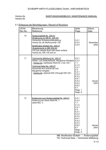
SCHEMPP-HIRTH FLUGZEUGBAU GmbH., KIRCHHEIM/TECK<br />
Ventus-2a WARTUNGSHANDBUCH / MAINTENANCE MANUAL<br />
Ventus-2b<br />
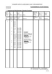
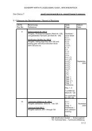
0.1 Erfassung der Berichtigungen / Record of Revisions<br />
Lfd.Nr.<br />
Rev.No.<br />
10<br />
11<br />
12<br />
Benennung<br />
Reference<br />
Änderungsblatt Nr. 349-41<br />
(Ergänzung zu ÄB-Nr. 349-42)<br />
Versenkte Schwerpunktkupplung<br />
Ventus-2a, ab Werknummer 130<br />
Modification Bulletin No. 349-41<br />
(Supplements to MB 349-42)<br />
C/G tow release flush with lower surface<br />
Ventus-2a, S/N 130 and on<br />
Technische Mitteilung Nr. 349-27<br />
Höhen- und Seitenleitwerk, Maughmer-Winglets<br />
- Ventus-2a: wahlweise Werk-Nr. 2 bis 120 –<br />
Technical Note No. 349-27<br />
Horizontal and vertical tail unit,<br />
Maughmer-winglets<br />
- Ventus-2a: optional S/N 2 through S/N 120 -<br />
Ergänzung zum Änderungsblatt Nr. 349-31<br />
Änderung am Stück Werk-Nr. 1<br />
siehe Rev. 3<br />
Seite<br />
Page<br />
0.2.1<br />
0.2.2<br />
5.2.4<br />
0.2.1<br />
0.2.2<br />
1.1<br />
2.1.2<br />
2.2.1<br />
2.3<br />
5.2.1<br />
5.2.3<br />
6.2.2<br />
6.4.1<br />
6.4.2<br />
6.4.3<br />
6.6.2<br />
6.7<br />
Diagr. 1<br />
Diagr. 6<br />
0.2.1<br />
0.2.2<br />
1.1<br />
2.1.2<br />
2.2.1<br />
2.3<br />
5.2.1<br />
5.2.3<br />
6.2.2<br />
6.4.1<br />
6.4.2<br />
6.4.3<br />
6.6.2<br />
6.7<br />
Diagr. 1<br />
Diagr. 6<br />
Datum<br />
Date<br />
Dezember<br />
2002<br />
Januar<br />
2003<br />
Januar<br />
2003<br />
MB: Modification Bulletin – Änderungsblatt<br />
TN: Technical Note – Technische Mitteilung<br />
0.1.4
SCHEMPP-HIRTH FLUGZEUGBAU GmbH., KIRCHHEIM/TECK<br />
Ventus-2a WARTUNGSHANDBUCH / MAINTENANCE MANUAL<br />
Ventus-2b<br />
0.2 Verzeichnis der Seiten / List of effective pages<br />
Seite / Page<br />
0.1.1<br />
0.1.2<br />
0.1.3<br />
0.1.4<br />
0.2.1<br />
0.2.2<br />
0.2.3<br />
0.3.1<br />
0.3.2<br />
0.3.3<br />
1.1<br />
1.2.1<br />
1.2.2<br />
1.2.3<br />
1.3<br />
1.4<br />
2.1.1<br />
2.1.2<br />
2.2.1<br />
2.2.2<br />
2.3<br />
2.4<br />
3.1.1<br />
3.1.2<br />
3.2.1<br />
3.2.2<br />
3.2.3<br />
3.2.4<br />
3.3.1<br />
3.3.2<br />
Datum / Date Bezug / Reference<br />
August 1995<br />
August 1995<br />
August 1995<br />
Januar 2003<br />
August 1995<br />
August 1995<br />
August 1995<br />
August 1995<br />
August 1995<br />
August 1995<br />
Januar 2003<br />
Januar 2003<br />
August 1995<br />
Januar 2003<br />
Dezember 2002<br />
August 1995<br />
August 1995<br />
August 1995<br />
August 1995<br />
August 1995<br />
August 1995<br />
August 1995<br />
TN 349-27<br />
TN 349-27<br />
TN 349-27<br />
TN 349-27<br />
Rev. 8<br />
0.2.1
SCHEMPP-HIRTH FLUGZEUGBAU GmbH., KIRCHHEIM/TECK<br />
Ventus-2a WARTUNGSHANDBUCH / MAINTENANCE MANUAL<br />
Ventus-2b<br />
0.2 Verzeichnis der Seiten / List of effective pages<br />
Seite / Page<br />
4.1<br />
4.2<br />
4.3<br />
5.1.1<br />
5.1.2<br />
5.2.1<br />
5.2.2<br />
5.2.3<br />
5.2.4<br />
5.3<br />
5.4.1<br />
5.4.2<br />
5.4.3<br />
6.1<br />
6.2.1<br />
6.2.2<br />
6.3<br />
6.4.1<br />
6.4.2<br />
6.4.3<br />
6.5<br />
6.6.1<br />
6.6.2<br />
6.7<br />
Datum / Date Bezug / Reference<br />
August 1995<br />
August 1995<br />
August 1995<br />
Dezember 2002<br />
August 1995<br />
Januar 2003<br />
August 1995<br />
Januar 2003<br />
August 1995<br />
August 1995<br />
August 1995<br />
August 1995<br />
August 1995<br />
August 1995<br />
August 1995<br />
Januar 2003<br />
August 1995<br />
Januar 2003<br />
Januar 2003<br />
Januar 2003<br />
August 1995<br />
August 1995<br />
Januar 2003<br />
Januar 2003<br />
Rev. 8<br />
TN 349-27<br />
TN 349-27<br />
TN 349-27<br />
TN 349-27<br />
TN 349-27<br />
TN 349-27<br />
TN 349-27<br />
TN 349-27<br />
0.2.2
SCHEMPP-HIRTH FLUGZEUGBAU GmbH., KIRCHHEIM/TECK<br />
Ventus-2a WARTUNGSHANDBUCH / MAINTENANCE MANUAL<br />
Ventus-2b<br />
0.2 Verzeichnis der Seiten / List of effective pages<br />
Seite / Page<br />
4.1<br />
4.2<br />
4.3<br />
5.1.1<br />
5.1.2<br />
5.2.1<br />
5.2.2<br />
5.2.3<br />
5.2.4<br />
5.3<br />
5.4.1<br />
5.4.2<br />
5.4.3<br />
6.1<br />
6.2.1<br />
6.2.2<br />
6.3<br />
6.4.1<br />
6.4.2<br />
6.4.3<br />
6.5<br />
6.6.1<br />
6.6.2<br />
6.7<br />
Datum / Date Bezug / Reference<br />
August 1995<br />
August 1995<br />
August 1995<br />
Dezember 2002<br />
August 1995<br />
Januar 2003<br />
August 1995<br />
Januar 2003<br />
August 1995<br />
August 1995<br />
August 1995<br />
August 1995<br />
August 1995<br />
August 1995<br />
August 1995<br />
Januar 2003<br />
August 1995<br />
Januar 2003<br />
Januar 2003<br />
Januar 2003<br />
August 1995<br />
August 1995<br />
Januar 2003<br />
Januar 2003<br />
Rev. 8<br />
TN 349-27<br />
MB 349-38, TN 349-27<br />
TN 349-27<br />
TN 349-27<br />
TN 349-27<br />
TN 349-27<br />
TN 349-27<br />
TN 349-27<br />
0.2.2
SCHEMPP-HIRTH FLUGZEUGBAU GmbH., KIRCHHEIM/TECK<br />
Ventus-2a MAINTENANCE MANUAL<br />
Ventus-2b<br />
1. Description of components and systems<br />
NOTE:<br />
Further descriptions and assembly are provided on sections 1.4, 1.5, and 7<br />
of the Flight Manual.<br />
1.1 Airframe<br />
The model Ventus-2a and Ventus-2b are single-seat high performance sailplanes,<br />
constructed from fiber reinforced plastic (FRP), featuring wingflaps<br />
and a T-tail (with fixed horizontal stabilizer and elevator).<br />
Wing<br />
The wing shells are a CFRP/foam-sandwich with spar flanges made from<br />
carbon fiber rovings and shear webs constructed as a CFRP/foam-sandwich.<br />
Fuselage<br />
This is a pure carbon fiber lay-up with a Kevlar and glass fiber reinforcement<br />
in the cockpit area for high energy absorbtion.<br />
Horizontal tailplane<br />
The horizontal tailplane consists of a fixed stabilizer with elevator.<br />
The stabilizer is a GFRP/foam-sandwich, the elevator halves are a pure<br />
carbon fiber lay-up.<br />
Vertical tail<br />
Both fin and rudder are constructed as a glass fiber/foam-sandwich.<br />
January 2003<br />
Revision 11 TN-No. 349-27 1.1
SCHEMPP-HIRTH FLUGZEUGBAU GmbH., KIRCHHEIM/TECK<br />
Ventus-2a MAINTENANCE MANUAL<br />
Ventus-2b<br />
15.0 m [ 49.21 ft ]<br />
3°<br />
TAILPLANE INCIDENCE<br />
-2.5°<br />
2.3 m [ 7.55 ft ]<br />
ELEVATOR<br />
+3 mm<br />
2 mm<br />
+0.12 in. ]<br />
0.08 in. ]<br />
44<br />
0.23°<br />
Up or down<br />
[ 1.73<br />
323 mm [ 12.72 in. ]<br />
138 mm<br />
[ 5.43 in. ]<br />
Ventus-2a - 6.41 m [ 21.03 ft ]<br />
RUDDER<br />
To either side: 155 ± 15 mm [ 6.10 ± 0.59 in. ]<br />
AILERONS (flaps set at "0")<br />
33 ± 3 mm<br />
Up<br />
[ 1.30 ± 0.12 in. ]<br />
25 ± 3 mm<br />
Down<br />
[ 0.98 ± 0.12 in. ]<br />
126 mm<br />
[ 4.96 in. ]<br />
325 ± 25 mm<br />
[ 12.80 ± 0.98 in. ]<br />
30 ± 2 mm<br />
[ 1.18 ± 0.08 in. ]<br />
0 ± 2 mm<br />
[ 0 ± 0.08 in. ]<br />
22 ± 2 mm<br />
[ 0.87 ± 0.08 in. ]<br />
FLAPS<br />
set at "S1" (up)<br />
set at "0" (neutral)<br />
Sailplane attitude for all measurements:<br />
Tail jacked up such that a wedge-shaped block,<br />
100 : 3.125, placed on the rear top fuselage, is<br />
horizontal along its upper edge.<br />
set at "L" (down)<br />
RIGGING DATA AND CONTROL SURFACE DEFLECTIONS<br />
January 2003<br />
Revision 11 TN-No. 349-27 2.1.2
SCHEMPP-HIRTH FLUGZEUGBAU GmbH., KIRCHHEIM/TECK<br />
Ventus-2a MAINTENANCE MANUAL<br />
Ventus-2b<br />
2.3 Play in the control circuits<br />
With the cockpit controls fixed, the play at the control surfaces must not exceed<br />
the following values:<br />
Inboard +/- 2.0 mm measured 126 mm behind hinge axis<br />
aileron: (+/- 0.08 in.) (4.96 in.)<br />
Between inbd.<br />
and mid +/- 2.0 mm measured 106 mm behind hinge axis<br />
aileron: (+/- 0.08 in.) (4.17 in.)<br />
Between mid<br />
and outbd. +/- 1.0 mm measured 88 mm behind hinge axis<br />
aileron: (+/- 0.04 in.) (3.46 in.)<br />
Elevator: +/- 3.0 mm measured 138 mm behind hinge axis<br />
(+/- 0.12 in.) (5.43 in.)<br />
If there is excessive play in the hinge bearings and/or linkages, they must be<br />
replaced or the manufacturer should be contacted regarding possible measures<br />
to reduce the play.<br />
The rudder control circuit is an open circuit, operated directly by control cables,<br />
and is therefore not subject to play.<br />
January 2003<br />
Revision 11 TN-No. 349-27 2.3
SCHEMPP-HIRTH FLUGZEUGBAU GmbH., KIRCHHEIM/TECK<br />
Ventus-2a MAINTENANCE MANUAL<br />
Ventus-2b<br />
5.2 Tow release(s) – removal and reinstallation<br />
Nose tow release mechanism (option)<br />
The nose tow release is located in the fuselage nose cone.<br />
It must be checked regularly for damage and also be cleaned and greased.<br />
Model "Ventus-2a": To remove the nose tow release proceed as follows:<br />
- Disconnect gas strut from panel mounting frame and withdraw<br />
frame axle so that the frame/panel assembly can be moved aside.<br />
- Remove nose access panel (by undoing the six mounting bolts), the tow<br />
release is now accessible.<br />
- It is removed by disconnecting the release cable from the actuating<br />
segment, undoing the four (4) mounting bolts and pulling it clear to the<br />
rear.<br />
Be sure that the electrical bonding strap is reattached when reinstalling the<br />
nose tow release mechanism (see sketch below).<br />
Torque: M4 2Nm (1.4 lbft)<br />
M5 5 Nm (3.6 lbft)<br />
EXTRACTED FROM DRAWING<br />
NO. HS08-10.108<br />
4 mounting bolts<br />
nose tow<br />
release type E 85<br />
actuating segment<br />
ground strap<br />
nose release access panel<br />
(attached by 6 bolts)<br />
January 2003<br />
Revision 11 TN-No. 349-27 5.2.1
SCHEMPP-HIRTH FLUGZEUGBAU GmbH., KIRCHHEIM/TECK<br />
Ventus-2a MAINTENANCE MANUAL<br />
Ventus-2b<br />
EXTRACTED FROM DRAWING<br />
NO. HS11-10.201<br />
tow release<br />
EUROPA G 88<br />
1<br />
3<br />
2<br />
4<br />
January 2003 (S/N 2 through 109)<br />
Revision 11 TN-No. 349-27 5.2.3<br />
5<br />
to be attached by bolts No. 2 and 5
SCHEMPP-HIRTH FLUGZEUGBAU GmbH., KIRCHHEIM/TECK<br />
Ventus-2a MAINTENANCE MANUAL<br />
Ventus-2b<br />
EXTRACTED FROM DRAWING<br />
NO. S08 RB 851<br />
tow release<br />
EUROPA G 88<br />
1<br />
2<br />
4<br />
3<br />
(S/N 110 through 120)<br />
January 2003 MB-No. 349-38<br />
Revision 11 TN-No. 349-27 5.2.3<br />
5<br />
to be attached by bolts No. 2 and 5
SCHEMPP-HIRTH FLUGZEUGBAU GmbH., KIRCHHEIM/TECK<br />
Ventus-2a MAINTENANCE MANUAL<br />
Ventus-2b<br />
Datum plane: Wing leading edge at root rib<br />
Aircraft attitude: Tail jacked up such that a wedge-shaped<br />
block, 100 : 3.125 for model “Ventus-2a”<br />
placed on the rear top fuselage, is horizontal<br />
along its upper edge.<br />
Distance main wheel<br />
model “Ventus-2a”: a = 106 mm (4.17 in.)<br />
Distance tail wheel/skid<br />
model “Ventus-2a”: b = 3927 mm (154,61 in.)<br />
Empty mass c/g position:<br />
C/G position in flight:<br />
x = W2 x b<br />
W<br />
(just given for the case that the “c/g position in flight” is to be determined by<br />
weighing rather than by computing it on the basis of the empty mass c/g position)<br />
The aircraft is to be weighed fully equipped (pilot with parachute and complete<br />
outfit incl. barograph, cushions, cameras etc.) Seat back and rudder pedals<br />
should be correctly adjusted for this purpose.<br />
January 2003<br />
Revision 11 TN-No. 349-27 6.2.2<br />
x =<br />
+ a<br />
W 2 loaded x b<br />
W empty + W disposable<br />
+ a
SCHEMPP-HIRTH FLUGZEUGBAU GmbH., KIRCHHEIM/TECK<br />
Ventus-2a MAINTENANCE MANUAL<br />
Ventus-2b<br />
6.4 Empty mass and empty mass c/g position<br />
a) Empty mass<br />
The basic empty mass of a “Ventus-2a” or “Ventus-2b” is the sailplane<br />
• without pilot<br />
• without parachute and<br />
• without water ballast<br />
but including all its fixed equipment.<br />
b) Empty mass center of gravity<br />
It must always be ensured that the empty mass center of gravity remains<br />
within the permitted range.<br />
If necessary, compensating ballast weights must be installed.<br />
If the empty mass c/g limits (see diagram on page 6.4.3) and the load<br />
limits on the seat (see load chart) are complied with, the center of gravity<br />
in flight will remain within the permitted range.<br />
The empty mass c/g ranges shown in the diagram on page 6.4.3 are<br />
derived from the following seat loads:<br />
Forward c/g limits: With a maximum seat load of 110 kg (242.5 lb)<br />
and with maximum permitted water ballast<br />
Rearward c/g limits: With various minimum seat loads, and a baggage<br />
load of 2.0 kg (4.4 lb)<br />
To facilitate the checking of the empty mass center of gravity, the table<br />
on page 6.4.2 shows – at different empty mass values – the maximum<br />
permissible load on the tail wheel (or skid), with various seat loads and<br />
in relation to the most rearward c/g position.<br />
The actual load on the tail wheel (or skid) is determined with the aircraft<br />
in weighing attitude, i.e. main wheel on the ground and tail jacked up as<br />
described on page 6.2.1.<br />
If the load on the tail wheel (or skid) does not exceed the corresponding<br />
value in the table, the center of gravity is within the permitted range.<br />
January 2003<br />
Revision 11 TN-No. 349-27 6.4.1
SCHEMPP-HIRTH FLUGZEUGBAU GmbH., KIRCHHEIM/TECK<br />
Ventus-2a MAINTENANCE MANUAL<br />
Ventus-2b<br />
Ventus-2a:<br />
Empty mass<br />
Load on tail wheel (or skid) with a minimum seat load of:<br />
70 154 75 165 80 176 85 187 90 198<br />
kg lb kg lb kg lb kg lb kg lb kg lb<br />
230 507 29.4 64.8 30.4 67.0 31.4 69.2 32.5 71.7 33.5 73.9<br />
235 518 29.7 65.5 30.7 67.7 31.7 69.9 32.8 72.3 33.8 74.5<br />
240 529 30.0 66.1 31.0 68.3 32.1 70.8 33.1 73.0 34.1 75.2<br />
245 540 30.3 66.8 31.4 69.2 32.4 71.4 33.4 73.6 34.5 76.1<br />
250 551 30.6 67.5 31.7 69.9 32.7 72.1 33.8 74.5 34.8 76.7<br />
255 562 31.0 68.3 32.0 70.5 33.0 72.8 34.1 75.2 35.1 77.4<br />
260 573 31.3 69.0 32.3 71.2 33.4 73.6 34.4 75.8 35.4 78.0<br />
265 584 31.6 69.7 32.7 72.1 33.7 74.3 34.7 76.5 35.8 78.9<br />
270 595 31.9 70.3 33.0 72.8 34.0 75.0 35.1 77.4 36.1 79.6<br />
January 2003<br />
Revision 11 TN-No. 349-27 6.4.2
SCHEMPP-HIRTH FLUGZEUGBAU GmbH., KIRCHHEIM/TECK<br />
Ventus-2a MAINTENANCE MANUAL<br />
Ventus-2b<br />
Empty mass c/g range<br />
EMPTY MASS C/G POSITION (mm / in.) AFT OF DATUM<br />
in. mm<br />
27.56 700<br />
27.17 690<br />
26.77 680<br />
26.38 670<br />
25.98 660<br />
25.59 650<br />
25.20 640<br />
24.80 630<br />
24.41 620<br />
24.02 610<br />
23.62 600<br />
23.23 590<br />
22.83 580<br />
22.44 570<br />
22.05 560<br />
21.65 550<br />
21.26 540<br />
20.87 530<br />
20.47 520<br />
20.08 510<br />
230<br />
507<br />
V e n t u s - 2 a<br />
V e n t u s - 2 a<br />
240<br />
529<br />
250<br />
551<br />
EMPTY MASS (kg / lb)<br />
January 2003<br />
Revision 11 TN-No. 349-27 6.4.3<br />
260<br />
573<br />
permissible rearmost empty mass<br />
c/g position with a minimum<br />
seat load of :<br />
90 kg<br />
198 lb<br />
85 kg<br />
187 lb<br />
80 kg<br />
176 lb<br />
75 kg<br />
165 lb<br />
70 kg<br />
154 lb<br />
FOREMOST EMPTY<br />
MASS C/G POS.<br />
270 kg<br />
595 lb
SCHEMPP-HIRTH FLUGZEUGBAU GmbH., KIRCHHEIM/TECK<br />
Ventus-2a MAINTENANCE MANUAL<br />
Ventus-2b<br />
For establishing a „Weight & Balance Report“ the following lever arms<br />
are to be used:<br />
C/G position of pilot<br />
(with parachute or back cushion)<br />
Ventus-2a: 455 mm (17.91 in.) forward of datum<br />
C/G position of wing water ballast<br />
179 mm (7.05 in.) aft of datum<br />
C/G position of water ballast or battery in fin<br />
Ventus-2a: 4092 mm (161,11 in.) aft of datum<br />
C/G position of battery in fin<br />
Ventus-2a: 3995 mm (157,28 in.) aft of datum<br />
C/G position of trim ballast mount<br />
Ventus-2a: 1635 mm (64.37 in.) forward of datum<br />
C/G position of battery tray at base of instrument panel<br />
Ventus-2a: 1120 mm (44,09 in.) forward of datum<br />
January 2003<br />
Revision 11 TN-No. 349-27 6.6.2
SCHEMPP-HIRTH FLUGZEUGBAU GmbH., KIRCHHEIM/TECK<br />
Ventus-2a MAINTENANCE MANUAL<br />
Ventus-2b<br />
6.7 Mass – C/G diagram<br />
ALL - UP MASS (kg / lb)<br />
lb kg<br />
1157 525<br />
1102 500<br />
992 450<br />
882 400<br />
772 350<br />
761 345<br />
750 340<br />
661 300<br />
654 296.6<br />
551 250<br />
FOREMOST C/G POSITION<br />
220<br />
8.66<br />
MAXIMUM ALL-UP MASS<br />
250<br />
9.84<br />
PERMITTED<br />
RANGE<br />
264.9<br />
10.43 296.2<br />
11.66 300<br />
11.81<br />
340.9<br />
13.42<br />
X in flight (mm / in.) aft of datum<br />
with optional water<br />
ballast fin tank<br />
January 2003<br />
Revision 11 TN-No. 349-27 6.7<br />
REARMOST C/G POSITION<br />
350 mm<br />
13.78 in.<br />
360<br />
14.17
SCHEMPP-HIRTH FLUGZEUGBAU GmbH., KIRCHHEIM/TECK<br />
Ventus-2a MAINTENANCE MANUAL<br />
Ventus-2b<br />
FUSELAGE CONTROLS<br />
1. Flaps and ailerons<br />
2. Airbrakes<br />
3. Elevator<br />
4. Elevator trim<br />
January 2003<br />
Revision 11 TN-No. 349-27 DIAGRAM 1
SCHEMPP-HIRTH FLUGZEUGBAU GmbH., KIRCHHEIM/TECK<br />
Ventus-2a MAINTENANCE MANUAL<br />
Ventus-2b<br />
1075 mm<br />
42.32 in.<br />
INSPECTION OPENING IN FIN<br />
(to be cut if required)<br />
∅20 mm<br />
∅0.79 in.<br />
parallel to<br />
shroud on fin<br />
to be measured<br />
at outer edge<br />
of tube<br />
390 mm<br />
15.35 in.<br />
shroud on fin<br />
Should it become necessary to replace the vertical elevator<br />
actuating rod, an additional opening may be cut into the fin<br />
on the far side.<br />
January 2003<br />
Revision 11 TN-No. 349-27 DIAGRAM 6
SCHEMPP-HIRTH FLUGZEUGBAU GmbH., KIRCHHEIM/TECK<br />
Ventus-2a MAINTENANCE MANUAL<br />
Ventus-2b<br />
70<br />
880<br />
Colour to be orange (RAL-Code No. 2004)<br />
or red (RAL-Code No. 3000 or 3024)<br />
120<br />
ANTI-COLLISION MARKINGS (optional)<br />
25<br />
80<br />
130 130 130 130<br />
130 130 130<br />
80<br />
80<br />
20°<br />
80<br />
80<br />
80<br />
80<br />
PROPOSAL 1 PROPOSAL 2 PROPOSAL 3 PROPOSAL 4<br />
January 2003<br />
Revision 1 TN-No. 349-27
SCHEMPP-HIRTH FLUGZEUGBAU GmbH., KIRCHHEIM/TECK<br />
Ventus-2a REPAIR INSTRUCTIONS<br />
Ventus-2b<br />
REPAIR INSTRUCTIONS FOR „Ventus-2a“ AND „Ventus-2b“<br />
The components of these sailplanes are constructed as follows:<br />
1. Wing<br />
CFRP/foam-sandwich, with HEREX C 70.55,<br />
thickness 6 mm and 8 mm (0.24 and 0.31 in.)<br />
2. Ailerons<br />
Inboard:<br />
Mid and<br />
CFRP/foam-sandwich, with HEREX C 70.55,<br />
thickness 4 mm (0.16 in.)<br />
outboard: Pure CFRP-shell<br />
3. Winglet<br />
Pure GFRP/CFRP-shell<br />
4. Fuselage<br />
Forward section: Pure CFRP/Kevlar/GFRP-shell<br />
Aft section: Pure CFRP-shell<br />
5. Fin<br />
GFRP/foam-sandwich, with HEREX C 70.55,<br />
thickness 6 mm (0.24 in.)<br />
6. Rudder<br />
GFRP/foam-sandwich, with HEREX C 70.55,<br />
thickness 4 mm (0.16 in.)<br />
7. Horizontal stabilizer<br />
GFRP/foam-sandwich, with HEREX C 70.55,<br />
thickness 6 mm (0.24 in.)<br />
8. Elevator halves<br />
Pure CFRP-shell<br />
January 2003<br />
Revision 1 TN-No. 349-27 - 1 -