Overall Dimensions - MAXGroupOnline
Overall Dimensions - MAXGroupOnline
Overall Dimensions - MAXGroupOnline

You also want an ePaper? Increase the reach of your titles
YUMPU automatically turns print PDFs into web optimized ePapers that Google loves.
L&T SWITCHGEARS A F E & S U R EMoulded CaseCircuit Breakers
IntroductionLarsen & Toubro infuses engineering with imagination. The Company offers a wide range ofadvanced solutions in the field of Engineering, Construction, Electrical & Automation,Machinery and Information Technology.L&T Switchgear, a part of the Electrical & Automation business, is India's largestmanufacturer of low voltage switchgear, with the scale, sophistication and range to meetglobal benchmarks. With over five decades of experience in this field, the Company todayenjoys a leadership position in the Indian market with a growing international presence.It offers a complete range of products including powergear, controlgear, industrialautomation, building electricals & automation, reactive power management, energy meters,and protective relays. These products conform to Indian and International Standards.Therange, a new generation of MCCBs, stands out due to its state-of-the-artdesign, contemporary user-friendly features, wide choice of protective releases,ergonomics, aesthetics and compactness.Therange complies with the latest standards like IEC 60947-2, EN 60947-2 & IS13947-2. The products conform to international standards, carry markings and are& CB certified. The range is specially designed for tropical conditions, ensuringreliable performance at high ambient and humid environments.Therange is designed to meet the changing needs of users after extensiveanalysis and user feedback. The range can satisfy the most demanding systemrequirements.Therange, complimented by a wide range of accessories, offer total solution tocustomer applications ensuring operational safety, reliability and versatility.Switchgear Factory, Mumbai
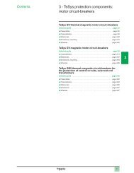
ContentsRange1Protection Releases2State-of-the-art technology4Accessories7Technical Data11Time - Current Characteristic Curves13<strong>Overall</strong> <strong>Dimensions</strong>16DN0DN1 DN2 DN3 DN4
The Complete RangeFeaturesFrom 20 A to 1250 A3 Pole & 4 PoleChoice of 36kA/50kA/70kA breaking capacities.With protection releases in Microprocessor, Thermal-Magnetic and only MagneticMCCBs for motor backup protectionMCCBs for distribution and SD versionsManual, rotary or motorised versionsWide range of internal and external accessoriesRated CurrentReleaseRated CurrentReleaseRated CurrentReleaseRated CurrentReleaseRated CurrentReleaseDN020, 25, 32, 40, 50, 63, 80, 100 AThermal-MagneticDN1100, 125, 160, 200, 250 AThermal-MagneticDN232, 40, 50, 63, 80, 100, 125, 160, 200, 250 A40, 63, 100, 160, 250 AThermal-MagneticMicroprocessorDN3320, 400, 500, 630 A400, 630 AThermal-MagneticMicroprocessorDN4800, 1000, 1250 AMicroprocessorBreaking CapacitiesBreakingcapacity36kA50kA70kAOld TypeDesignationS (35kA)HLNew TypeDesignationDNS1Note : Since there is no change in the constructional aspect of the MCCBs, the product Certification with old designationremain valid with new type designation.
Protection ReleasesThermal-Magnetic ReleaseFeatures of Thermal-Magnetic ReleaseAdjustable overload settingsAdjustable short circuit settingsTrue RMS sensingNo contact with live partsProtectionSettingsOverloadShort circuitEarth faultDN0 & DN180% - 100% In9 In (fixed)ExternalDN2 & DN380% - 100% In6 - 10 InExternalMicroprocessor ReleaseFeatures of MTX 1.0 / 2.0 Microprocessor ReleaseOverload protection with inverse time delayShort circuit protection with selectable time delayInstantaneous over ride protection*Earth fault protection with selectable time delay*Neutral protection with selectable time delay*Push to trip buttonThermal memory enable / disablePower ON LEDSelf powered protectionsTrue RMS sensingCurrent metering (optional)*Panel mounted display (optional) for currentmetering *Latest trip record** Available with MTX 2.0 onlyRated CurrentCurrent setting, Ir (Ir = Xin)Time delay, tr (Inverse)Protection modeThermal memoryCurrent setting, Is (Ir = Xin)Protection modeTime delay, tsCurrent setting, IpMTX 1.0Overload (Phase)Short CircuitInstantaneous Over rideFrom 40 to 1250 AOFF, 0.4 to 1.0 in steps of 0.0510s at 6 Ir, 3s at 6 Ir, 10s at 7.2 Ir, 3s at 7.2 IrON/OFFEnable/Disable1.5, 2.5, 4.0, 5.5, 6.5, 8.0 IrON/OFF100ms/InstantaneousDN2-10In, DN3-400-10In, DN3-630-10In, DN4-10In2
Protection ReleasesRated CurrentCurrent setting, Ir (Ir = Xin)Time delay, tr (Inverse)Protection modeCurrent settingDelayProtection modeCurrent setting, Ir (Ir = xIn)DelayProtection modeCurrent setting, IpCurrent setting, IgTime delay, IgProtection modeMTX 2.0Overload (Phase)Overload (Neutral)Short CircuitInstantaneous Over rideEarth FaultFrom 40 to 1250 AOFF, 0.4 to 1.0 in steps of 0.0510s at 6 Ir,3s at 6 Ir, 10s at 7.2 Ir, 3s at 7.2 IrON/OFFOFF, 50%, 100% and 150% of phase setting200ms/depending on phase settingON/OFF1.5, 2.5, 4.0, 5.5, 6.5, 8.0 Ir20ms/100msON/OFFDN2-10In, DN3-400-10In, DN3-630-10In, DN4-10In0.2 to 0.5 In100ms/200msON/OFFOnly Magnetic release(for Motor backup protection)Only magnetic with instantaneous protection upto 10InFault level protection for complete starter upto 50kAType 2 charts available for DOL & Star/delta startersFrameTypeCurrent Range (A)PolesIcu(kA) @ 415V AC, 50Hz250 ADN2-250M100-250400 ADN3-400M320-4003P only50630 ADN3-630M500-630Switch Disconnector version(without protection release)FrameType250 ADN2-250SD400 ADN3-400SD630 ADN3-630SDCan be used as switching or Isolator devicesHigher withstand capacitiesWide range of accessories for remote operationCurrent Range (A)PolesIcw (kA) for 1sec.100-2503/43.6320-4003/46500-6303/463
im pState-of-the-art technologyFaster trippingThe unique speed contact system accelerates the opening ofcontacts during short circuit. This ensures faster tripping anultimate current limiting feature. The result-very low let-through,cut-off current and fault clearing timeMechanical Anti-reclosingThis unique feature ensures that under short circuit conditions,the contacts open and latch even before the release gives a tripcommand to the mechanism. This avoids contact re-closingand bounceLow watt lossThe entire current carrying path is optimally designed to achievevery low watt lossPositive IsolationThe MCCB knob indicates the true position of thecontactsU e : 415V, 50/ 60Hz.U : 8kVI cu : 50 kA, I cs:100%IcuCAT:IS 13947-2 IEC 60947-2 EN 60947-2ADN3-630NDouble InsulationThe internal accessories are housed in insulatedcasings to ensure first level of insulation. When thefront cover is opened for the fixing of internalaccessories, the MCCB is totally insulated ensuringthe double insulationExtra Gripon HandleMarkingCE Marking ensures use of superior engineeringplastic, meeting all requirements of flammability andglow wire testing path is optimally designed toachieve very low watt loss4
e mI :70kA,U i p:8kVCAT:AU e :415 V , 50/60Hz. impI cu :70kA, cs cuU :8kVCAT:AI S 13947 -2 IEC 60947 -2 EN 60947-2cs cuimpState-of-the-art technologyCommon Internal accessoriesThe internal accessories remain same across DN0 / DN1& DN2 / DN3 / DN4* and they are easy to install snap fittypeI :100%I DN2-250SU e : 415 V, 50/60Hz.U : 8kVI cu : 50k A,I :100% IC AT: AIS 13947-2 IEC 60947-2 EN 60947-2DN3-630NLINENo load line biasEither side of MCCB terminal can be used as load or lineU :415V, 50/60Hz.cu I :100%Ics cu DN2-250SI S 13947- 2 IEC 60947- 2 E N 60947-2LOADTerminal finger proofingFront terminal plates conceal the terminals to prevent humancontact thus achieving complete finger proofingRelease shroudingRelease is shrouded from the front thus preventing tamperingby unauthorized personSafer release adjustmentsNo live parts are in contact during release adjustmentsCommon front adjustments for protection releaseOverload & short circuit setting can be adjusted from frontusing a common knob for all the polesVisibilityPush to trip button and release ratings are visible even whenrelease plate is fitted* Except under voltage release.5
State-of-the-art technologyMatrix 1.0 /2.0-FAB (Features / Advantages / Benefits)FeaturesPanel mounted Display for current meteringDigital Current meteringInbuit earth fault protectionThermal memoryPrecise selection of setting parametersCE markingRelease shroudDIP switchesMultiple trip class 6Ir & 7.2IrSelf poweredOLED displayAdvantagesNo need to unlock the doorCommon display module for DN2/3/4No need of separate CTs & metersDigital values can be processed further for Energymanagement functionsNo need of external earth fault relayProtects system with cyclic overloadsIncreases overall life of equipmentReduces production downtimeBalances between nuisance tripping & optimul protectionResults in high continuity of serviceAssures better qualityPrevent tampering with settingsEasy operation with precise selectionLess maintenance requiredProvides enhanced co-ordination with motorGuarantees the plant safetyNo need of external power supplyHassle free operationLess power consumptionwide viewing angleBenefitsSafetyConvenienceSavingConvenience & UpgradationSavingLonger installation life & SavingConvenienceReliable performanceSecurityConvenienceBetter performance & SafetySaving & ConvenienceSaving & Convenience6
cs cuNim pI u : 70kA,imp8 VCAT:Acu : 50kA cs cuC AT: AI : u 7 0kA,c 100 I uim pCAT:AAccessoriesInternal AccessoriesRange of MCCBs are offered with snap-fit type,easily installable internal accessories. There is no need toopen main cover and no live parts are accessed duringinstallation. TAC, Aux+TAC to be fitted in the right cavity &under voltage release to be fitted in left cavity.Auxiliary ContactList of Internal AccessoriesAuxiliary Contact 1 C/OAuxiliary Contact 2 C/OTrip Alarm ContactAuxiliary & Trip Alarm ContactShunt ReleaseUnder Voltage ReleaseU e :415V, 50/60Hz. U : kcs c DN2-250S2 IE 6 -c I :100%I uIS 13947-2 IEC 60947-2 EN 60947-2U e :415V, 50/60Hz.U :8kVc I : %s c DN2-250SIS 13947- C 0947-2 EN 60947 2MCCB with mid cover opened& Internal accessories fittedExternal AccessoriesExtended Rotary Handle (Panel Mounted)ROM mounts directly on MCCB without removalof mid coverClear ON/OFF/TRIP indicationClear view of MCCB rating label withROM mountedDirect access to push to trip button withROM mountedIP 54 degree of protection with extendedrotary handleUnique coupling to allow +3mm toleranceDoor interlock in ON position, with defeat facilityDoor interlock in OFF condition withpadlock featureAuto restoration of door interlockExternal keylock for mechanical interlockingUe : 415V, 50/ 60Hz.U imp: 8kVI , I :100%IIS 13947-2 IEC 60947-2 EN 60947-2DN3-630NExtended RotaryHandle:Panel MountedPanel Door MountedKey lock(To be used along withextended rotary handles)CAT: AU e : 415 V, 50/60 Hz.U : 8kVI cu: 50kA, I :100%IIS 13947-2 IEC 60947-2 E 60947-2DN3-630NRotary Operating MechanismThe rotary operating mechanism (ROM) forDirect & Extended versions.MCCBs are available inDirect rotary handle (MCCB mounted)These versions are available for the entire family ofMCCBs.7
Ics cuimpcs 0 cuimpTAccessoriesMechanical Interlocking Schemes1. Mechanical Interlocking Kit:Two MCCBs can be interlocked using base platemechanism, in side-by-side configuration.FeaturesFor 3 Pole & 4 Pole versionsFor DN2 & DN3 framesSite fittableUe : 415V, 50/ 60H z.U : 8kVcu : 50kA, I :100%ICAT: AIS 13947- 2 I EC 60947- 2 EN 60947-2DN3-630NUe: 415 V , 50/60H z.U : 8kVI cu : 50kA, I :10 %ICA : AIS 13947-2 I EC 60947- 2 EN 60947-2DN3-630NMIL with Base Plate2. Mechanical Interlocking using Key locks:For mechanical interlocking through Extended Rotary operating mechanism,a panel mounted key lock is available. The selection of the key lock as per thefollowing details,2 l/C2 I/C and 1 B/C3 I/C and 2 B/CAny 1 type of lock for both MCCBsLock 1 and Lock 2 for I/C and Lock 12 for B/CLocks 1, 2, 3 for I/Cs and Locks 12, 23 for B/CsKey Lock SelectionI/C 1 I/C 2 I/C 3Lock 1 Lock 2 Lock 3Incommers (I/C)Lock 12 Lock 23Bus couplers (B/C)B/C 1 B/C 2Type of lock1231223Exclusively operable by Key Nos.1231, 2 & 122, 3 & 238
AccessoriesExternal Neutral CTsFeaturesAdd on accessory for 3P MCCBReliable solution for Earth / Neutral fault protectionfor 3 Phase 4 wire systemStored Energy Electrical Operating MechanismFeaturesON / OFF & Charged/Discharged indicationFoolproof mountingSelector switch for Auto/Manual operationPadlock facility for locking in OFF position(3 nos locks)Resetting time < 250msec & Closing time< 90 msecHigher mechanical & electrical enduranceBack up fuse for extended motor protectionEasy access to the protection setting on MCCBTrue indication for ON/OFF & TripDN3 SE EOM data sheetOperating voltage (V AC) 240Operating voltage (%) 85-110%Closing time (ms) 90Opening time (ms) 250Power consumption (VA) 500Life / No. of operations 5000Door cut out (mmXmm)IP protection, on the frontOperating frequency96X96IP301/minMin. control impulse time (ms) 2009
AccessoriesAutomatic Source Transfer Switch Controller AuXC-1000AUTO TRANSFER CONTROLLER448 448LINE 1 LINE 2L1 L2 L3 HzL1 L2 L3 HzAuXC-1000ALARMTESTTESTThe AuXC-1000 controller brings simplicity andflexibility to an auto source transfer system. It has beendeveloped to control and supervise the automatic ormanual transfer of a utility load from a principal powersupply source to a stand-by. It sets a new benchmark inAuto source transfer switch controller technology.ONONOFFOFFONONWITHDRAWNWITHDRAWNTRIPTRIPLOADA01 LOW BATTERY VOLTAGE A04 LINE 2 SWITCH FAULT A07 LOAD NOT POWERED T. OUTA02 HIGH BATTERY VOLTAGE A05 LINE 1 WRONG PHASE SEQ. A08 GENERATOR NOT READYAUTOMANUALOFF/RESETIt includes all the necessary features to supervise andcontrol power supply sources, composed by energydistribution systems or generating sets, and the relativetransfer equipment, such as contactors, motorizedmoulded case circuit breakers and air circuit breakers.A03 LINE 1 SWITCH FAULTA06 LINE 2 WRONG PHASE SEQ.A09 EMERGENCY STOPThe automatic transfer takes place through AuXC-1000 wheneverconditions predefined by the user take place, for example:Power supply source not respecting programmed limitsThe need to have a very reliable power sourceThe need to use the most economical power sourceSome of the key features of this controller are:Front display for monitoring the system voltage and frequency and foronsite controller programmingSix programmable inputs and five programmable outputsFront test feature to simulate the operation of the diesel generator setStatus indication through 22 LEDsFlush mounting arrangementCommunication capableThe AuXC-1000 controller is compatible with U-Power range of Air circuitbreakers, range of MCCBs and MCX range of contactors.+AuXc-1000MIL with Base Plate & EOM10
Technical DataTESTEDACCESSORIESFrameTypeCurrent Range (A)PolesImpulse withstand Voltage (kV)Rated Operational Voltage (V) (MAX)Rated Insulation Voltage (V)Utilisation CategoryStandardIEC-60947-2Life spanOperating Frequency (Hz)Total Opening TimeFinger-proof TerminalsAmbient TemperatureStorage TemperatureMounting Positions<strong>Dimensions</strong> (W x D x H)3mmWeight (kg) (3/4 Pole)InternalExternalIcu(kA)Ics as % lcu230 / 240 V400 / 415 V500 V550 V600 V690 V250 V DC (3P in series)500 V DC (3P in series) L/ R
Time - Current Characteristic CurvesThermal-Magnetic ReleaseDN0-100DN1-250100001000010001000100100Time in Seconds10Time in Seconds10110.10.10.0112 4 6 8 10 200.011 10 100Multiples of CurrentMultiples of CurrentDN2-160/250DN3-400/630100001000010001000100100Time in Seconds10Time in Seconds10110.10.10.010.0112 4 6 8 102 4 6 8 1002Multiples of Current12 4 6 8102 4 6 8100Multiples of Current213
Time - Current Characteristic CurvesMicroprocessor ReleaseMTX 1.0/2.0-DN2/DN3/DN4100006 Ir1000Time in Seconds10010ToleranceTrip Time: ±20%10s13s0.1 1 1.2 6 10Multiples of CurrentMTX 1.0/2.0-DN2/DN3/DN4100007.2 Ir1000Time in Seconds1001010sToleranceTrip Time: ±20%13s0.11 1.2 7.2 10Current Multipies(Xlr)Multiples of Current14
Time - Current Characteristic CurvesMicroprocessor ReleaseShort Time Setting (STS)Earth Fault Setting11Time in Seconds0.1Inst100msTime in Seconds0.1200ms100mstolrancetrip time +20ToleranceTrip Time: +20%0.011 1.5 8 10 xlrMultiples of Current0.010.1 0.2 0.5 1 x lnMultiples of CurrentNeutral Setting1Time in Seconds0.1*Invs OFFToleranceTrip Time: +20%0.010.1 0.5 1 1.510 x IrMultiples of Current15
<strong>Overall</strong> <strong>Dimensions</strong>DN0-100 MCCB100 (4 pole)12.56.992525 2575 (3 pole)25.5 25 M3-Ø2.42.2529.548.5527625116.4130Ns1124639NCut-out 1orCut-out 2Mounting & Door Cutout DetailsDN0-100 with Spreader Links9235 3512735 35 3520 26086.1194.2172.2116.462.561.558130N1303845s2211 30.235 35 3512760Suitable for 35 x 7.5Top Hat Rail MountingRecommended CAT number for DN0 spreaders3PCM97785OOOO4PCM97921OOOONote : Spreaders are available as spare. It is recommended to use spreader linksfor enhancing termination capacityNote : Spreaders are available as spareAll dimension are in mm16
<strong>Overall</strong> <strong>Dimensions</strong>DN1-250 MCCB35 35 35Mounting Panel35 3570.5 70.5165145126N126N14110842.658.64635 35M4-Ø3.5140 (4P)105 (3P)For Four Pole38.8DN1-250 with Spreader Links601835 351835 35 35425722116514512638N464.554.5 54.554 54 541872 72197105 (3P)93.7Spreader Link 3P MCCB140 (4P)Recommended CAT number for DN1 spreaders3P4PST98053OOOOCM92007OOOOAll dimension are in mm17
<strong>Overall</strong> <strong>Dimensions</strong>DN2-250 MCCB35 3517.5 17.5NONTRIPOFF163 86146.515735 35 35 17.5105140Terminal width = 25.5.mm43 4386Mounting & DoorCut-out DetailsDN2-250 with Spreader Links183554.5 54.5 54.51828.612097.5438Ø1038275239ONTRIPOFFNONTRIPOFF17945 72.7A454.5 54.5Wider gap2035= == =144198.5RatingDimension (A)125-250A TM2663-100A TM25.5Recommended CAT number for DN2 spreadersNote : Spreaders are available as spare. It is recommended to usespreader links for enhancing termination capacity.32-50ARC breakers26.25283PST98053OOOO4PCM92007OOOOAll dimension are in mm18
<strong>Overall</strong> <strong>Dimensions</strong>DN3-400/630 MCCB183.443.5 43.5ONTRIPOFF14014223 41 6= =82.77822443.526.512143.5 43.5= =Terminal width = 28mmMounting & DoorCut-out DetailsDN3-400/630 with Spreader Links16562.5 62.5224.562 60.5 6222Wider gap111.5177.8AØ13ØF234ED266142ONTRIPOFFONTRIPOFFC43.5 26.5B5Wider gap 22.5402343.5 43.5142TypeDN3-400DN3-630A3941B3738C4555Recommended CAT numbers for DN3 spreadersD324344Rating3P4PE370390400AST98065OOOOST98066OOOONote : Spreaders are available as spare. It is recommended to usespreader links for enhancing termination capacity.F1311630AST98054OOOOCM92004OOOOAll dimension are in mm19
<strong>Overall</strong> <strong>Dimensions</strong>DN4-800/1000/1250 MCCB4 Pole 1822068 68 685724109.5330N326107278179.568 68DN4-800 MCCBwith Spreader LinksDN4-1000/1250 MCCBwith Spreader LinksDN4-800/1000/1250 MCCB60NAABA2415 510 15WidergapA A A28N60 24B155101585370854646195143C132.5105- 46 (N version)42 (S version)<strong>Dimensions</strong>Recommended CAT numbers for DN4 spreadersTypeABCRating3P4P800A883246800AST90361OOOOST90362OOOO1000/1250/1600A80300201000A /1250AST98055OOOOST98058OOOONote : Spreaders are available as spare. It is recommended to usespreader links for enhancing termination capacity.All dimension are in mm20
ROM Door cut-out detailsDirect ROM door cut-out detailL5L4NL3L2L1L1 = Mounting DepthL2/L3 = Panel Cut-outL4/L5 = Breaker Mounting ReferTypeDN0DN1L196.596.5L25873L35252L443.556.5L53754DN212296635366DN3146121877882Extended ROM door cut-out detailL2Ø50045L3Ø76NØ4L1=Minimum Panel Depth suggestedLL = Length of Shaft Required for Panel Depth L1Total Length of Shaft =275mmRefer Panel Cut DetailsTYPEL1LL2Refer Panel Cut DetailsL3DN0169L1 - 1197.569.5DN1169L1 - 11924.581.7DN2202L1 - 1522784DN3233L1 - 18339122DN4302L1 - 25269170All dimension are in mm21
<strong>Overall</strong> <strong>Dimensions</strong>MCCB with EOM (Stored Energy)DN3Mounting holes for MCCB43.5==264256Door45944962.1224N94Door cut outTCat. No.CM98130OOOOPanel Mounted Key Lock7248.52 Holes, Ø4.2Ø76Ø50045Ø50Cut-out for Handle Assembly1213668685852Cut-out for Panel Mounted Key Lock2.2Ø29All dimension are in mm22
<strong>Overall</strong> <strong>Dimensions</strong>DN2 MIL Kit372Ø10 Mounting Holes14114135209239177141141Holes for Breaker MountingDN3 MIL Kit436161 161Ø10 Mounting Holes56316346266161 161Holes for Breaker MountingAll dimension are in mm23
<strong>Overall</strong> <strong>Dimensions</strong>External Neutral CTsDN2 / DN3KLGBCDFBottom SideAJHBottom SideGØFEABCDEFGDN2 250A935947813510.277DN3 400A93.5584681.5401363.5DN3 630A93.5584681.54010.563.5Adaptor TerminalHJKLMDN2 250A15318926455DN3 400A153.5199.539560DN3 630A173.5219.539560ONTRIPNote: Adapter Terminals shown are not available with product.kindly refer accessories data for ordering separately.Circuit Breaker shown for reference only.OFFBottom Side>MAll dimension are in mm24
<strong>Overall</strong> <strong>Dimensions</strong>External Neutral CTsDN4HMNADJKGCBØFEDN4ABCDEFG800A13288.573.51176012.5921000/1250A13288.573.51176012.592DN4HJKLMN800A243022728073.561000/1250A243022728073.520NNote: Adapter Terminals shown are not available with product.kindly refer accessories data for ordering separately.Circuit Breaker shown for reference only.Special Note: Adapter Terminals for DN4 range of product are not symmetrical.Kindly insure proper orientation in assembly as shown in figure below.>LAll dimension are in mm25
<strong>Overall</strong> <strong>Dimensions</strong>Matrix Metering ModuleCommunication Module38173.387314.3602365Display Module5144.5109691.5All dimension are in mm26
Electrical Standard Products (ESP) Branch Offices:REGISTERED OFFICE ANDHEAD OFFICEL&T House, Ballard EstateP. O. Box 278Mumbai 400 001Tel: 022-67525656Fax: 022-67525858Website: www.Larsentoubro.comELECTRICAL STANDARD PRODUCTS (ESP)501, Sakar Complex IOpp. Gandhigram Rly. StationAshram RoadAhmedabad 380 009Tel: 079-66304006-11Fax: 079-66304025e-mail: esp-ahm@LNTEBG.com38, Cubbon Road, P. O. Box 5098Bangalore 560 001Tel: 080-25020100/25020324Fax: 080-25580525e-mail: esp-blr@LNTEBG.com131/1, Zone IIMaharana Pratap NagarBhopal 462 011Tel: 0755-4098721/7/ 8 / 9Fax: 0755-2769264e-mail: esp-bho@LNTEBG.comPlot No. 559, Annapurna ComplexLewis RoadBhubaneswar 751 014Tel: 0674-6451342, 2436696Fax: 0674-2537309e-mail: esp-bbi@LNTEBG.comSCO 32, Sector 26-DMadhya Marg, P. O. Box 14Chandigarh 160 026Tel: 0172-4646840, 4646853Fax: 0172-4646802e-mail: esp-chd@LNTEBG.com10, Club House Road,AnnasalaiChennai 600 002Tel: 044-28462072 / 4 / 5 / 2109Fax: 044-28462102 / 3e-mail: esp-maa1@lntebg.com67, Appuswamy RoadPost Bag 7156Opp. Nirmala CollegeCoimbatore 641 045Tel: 0422-2588120 / 1 / 5Fax: 0422-2588148e-mail: esp-cbe@LNTEBG.comL&T House, Group MIG-5PadmanabhpurDurg 491 001Tel: 0788-2213833 / 14 / 21 / 29Fax: 0788-2213820e-mail: esp-durg@LNTEBG.comKhairasol, Degaul AvenueDurgapur 713 212Tel: 2559848, 2559849, 2559844Fax: 0343-2553614e-mail: esp-dgp@LNTEBG.comMilanpur Road, Bamuni MaidanGuwahati 781 021Tel: 0361-2550562 / 65Fax: 0361-2551308e-mail: hazrasudipto@LNTEBG.comII Floor, Vasantha Chambers5-10-173, Fateh Maidan RoadHyderabad 500004Tel: 040-66720250Fax: 040-23296468e-mail: esp-hyd@LNTEBG.comD-24, Prithvi Raj Road, C-SchemeJaipur 302 001Tel: 0141-2385915 / 16 / 17 / 18Fax: 0141-2373280e-mail: esp-jai@LNTEBG.comAkashdeep Plaza, 2nd FloorP. O. GolmuriJamshedpur 831 003JharkhandTel: 0657-2312205 / 38Fax: 0657-2341250e-mail: esp-jam@LNTEBG.comSkybright Bldg; M. G. RoadRavipuram Junction, ErnakulamKochi 682 016Tel: 0484-4409420 / 4 / 5 / 7Fax: 0484-4409426e-mail: esp-cok@LNTEBG.com3-B, Shakespeare SaraniKolkata 700 071Tel: 033-44002572 / 3 / 4Fax: 033-22821025/7587e-mail: esp-ccu@LNTEBG.comA28, Indira Nagar, Faizabad RoadLucknow 226 016Tel: 0522-2312904 / 5 / 6Fax: 0522-2311671e-mail: esp-Lko@LNTEBG.comNo: 73, Karpaga Nagar, 8th StreetK. PudurMadurai 625007Tel: 0452-2537404, 2521068Fax: 0452-2537552e-mail: esp-mdu@LNTEBG.comEBG North Wing Office-Level 2Gate 7, Powai CampusMumbai 400 072Tel: 022-67052874 / 2737 / 1156Fax: 022-67051112e-mail: esp-bom@LNTEBG.com12, Shivaji NagarNorth Ambazari RoadNagpur 440 010Tel: 0712-2260012/3Fax: 0712-2260020/30e-mail: esp-nag@LNTEBG.com32, Shivaji MargP. O. Box 6223New Delhi 110 015Tel: 011-41419514 / 5 / 6Fax: 011-41419600e-mail: esp-del@LNTEBG.comL&T HouseP. O. Box 119191/1, Dhole Patil RoadPune 411 001Tel: 020-26135048/26164048Fax: 020-26124910, 26135048e-mail: esp-pnq@LNTEBG.com3rd FloorVishwakarma ChambersMajura Gate, Ring RoadSurat 395 002Tel: 0261-2473726Fax: 0261-2477078e-mail: esp-sur@LNTEBG.comRadhadaya ComplexOld Padra RoadNear Charotar SocietyVadodara 390 075Tel: 0265-6613610 / 1 / 2Fax: 0265-2336184e-mail: esp-bar@LNTEBG.com48-8-16, DwarakanagarVisakhapatnam 530 016Tel: 0891-6620411-2 / 3Fax: 0891-6620416e-mail: esp-viz@LNTEBG.comProduct improvement is a continuous process. For the latest information and special applications, please contact any of our offices listed here.Electrical Standard ProductsLarsen & Toubro LimitedPowai Campus, Mumbai 400 072Customer Interaction Center (CIC)BSNL / MTNL (toll free) : 1800 233 5858Reliance (toll free) : 1800 200 5858Tel : 022 6774 5858Fax : 022 6774 5859E-mail : cic@LNTEBG.comWebsite : www.LNTEBG.comd sine with MTX release 230212