WHP Cruise Summary Information - CLIVAR & Carbon ...
WHP Cruise Summary Information - CLIVAR & Carbon ...
WHP Cruise Summary Information - CLIVAR & Carbon ...

Create successful ePaper yourself
Turn your PDF publications into a flip-book with our unique Google optimized e-Paper software.
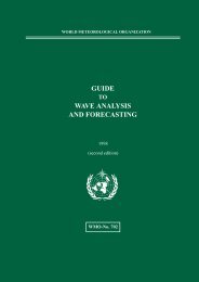
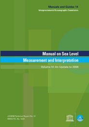
Station Locations for P15N Leg 1: Garrett180˚170˚W160˚W150˚W140˚W130˚W120˚W110˚W100˚W60˚N60˚N.0.050˚N.050˚N.0.0.040˚N.040˚N.0.0.0.030˚N.0.030˚N.0.0.020˚N.020˚N10˚N10˚N0˚180˚170˚W160˚W150˚W140˚W130˚W120˚W110˚W100˚W0˚Produced from .sum file by <strong>WHP</strong>O-SIO
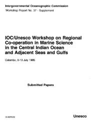
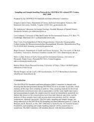
Station Locations for P15N Leg 2: Freeland180˚170˚W160˚W150˚W140˚W130˚W120˚W110˚W100˚W40˚N40˚N30˚N30˚N20˚N.020˚N.0.0.010˚N.010˚N.0.0.00˚.0.0.00˚.0.0.010˚S.0.010˚S.0.020˚S180˚170˚W160˚W150˚W140˚W130˚W120˚W110˚W100˚W20˚SProduced from .sum file by <strong>WHP</strong>O-SIO
A.2 <strong>Cruise</strong> <strong>Summary</strong> <strong>Information</strong>A.2.a Geographic boundariesOn September 6, the Tully sailed west from the mouth of Juan de Fuca Strait, along LinePR6. After completing 4 stations en route to Station PRS1, the vessel sailed for DutchHarbor, Alaska, where it refueled. Section P15N started near Dutch Harbor and continuedsouth along 165 W. At 24 N, we gradually shifted towards the West to coincide with aprevious NOAA section and the planned route of P15S. Most of the scientific crew werechanged in Honolulu after 35 days at sea. Leg 2 continued from 20 30 N, following acourse that moved gradually westward to 168 45 W at 10(N. We remained on thislongitude through the equator, then began a second southwestward course at 8 30 S thattook us to 170 W at 10 S. At 15 S, Leg 2 ended and the vessel sailed to American Samoa.A.2.b Stations occupiedCTD/rosette casts were done at 3 stations along PR6, PRS1 was reoccupied, and 70CTD/rosette stations along P15N were done during the first leg. Two rosettes were usedto collect 3225 samples for onboard analyses of salinity, oxygen, nutrients, CFCs, totalCO 2 and alkalinity. Additional samples were stored for 13 C, 14 C, 18 O and CH 4 . Continuousmeasurements of air and seawater CO2 were taken from the scientific seawater supply(Uncontaminated Sea Water). USW was also sampled for salinity, nutrients andchlorophyll a at almost all cast stations, and each degree of longitude between PRS1 andDutch Harbor. Tracers were occasionally collected from the USW supply.Table 1: Station Locations for USW-123.500000 48.266700-124.002500 48.299800-124.500300 48.449800-125.011700 48.539300-125.546800 48.578200-126.000000 48.600000-126.333300 48.616700-126.665700 48.649200-126.171700 48.693300-127.686700 48.743300-128.666700 48.816700-129.165800 48.856200-129.662000 48.892700-130.166700 48.933300-130.661700 48.966700-131.664700 49.044000-132.664500 49.122500-133.659200 49.200000-134.669700 49.283700-135.670000 49.350000-136.661500 49.415300-137.666700 49.650700-138.667200 49.566500-139.666700 49.633000-140.662700 49.701200-141.669500 49.767000-142.658300 49.835000-143.603200 50.000000-144.303700 50.001200-144.984500 50.003000-146.009200 50.206300-147.003500 50.401000-148.009500 50.596000-149.003800 50.786500-150.008300 50.979700-151.218300 51.208300-152.007300 51.359700-153.007000 51.550000-154.061500 51.748200-155.000800 51.924500-156.001500 52.112200-157.000000 52.295500-158.021700 52.488300-159.000200 52.666800-160.117800 52.874800-161.128300 53.041700-162.024200 53.183000-163.000200 53.286800-164.000800 53.394300-164.998300 53.640800-164.989500 53.920700-164.989300 53.744700-164.995700 53.500300-165.015000 53.249000-165.003700 52.998200-165.003000 52.739800-165.495700 52.238000-165.141700 51.358300-164.990800 50.967200-164.993200 50.499000-165.003000 50.000300-164.999000 49.493500-165.007300 49.004200
-165.000000 48.500200-164.999300 47.999500-164.991500 47.503800-164.995500 47.012700-165.000300 46.498000-164.999700 45.991800-165.162700 45.504000-164.755700 44.996700-164.790200 44.500200-164.995200 43.995000-165.009300 43.487200-164.990000 43.013300-164.999200 42.500000-164.995200 41.999700-164.997200 41.496800-165.005800 40.997700-165.023300 40.494300-165.000000 40.001300-164.907200 39.498200-165.000300 38.999200-164.998300 38.504800-165.003300 37.998300-165.001800 37.501800-164.999300 36.998000-165.006200 36.504700-165.002000 35.998000-165.004200 35.495000-164.995300 35.000800-165.000800 34.514700-164.993800 34.001300-165.000200 33.496300-165.014500 32.995300-164.995800 32.505000-164.995700 31.997700-165.006000 31.503200-165.006500 31.003700-165.000700 30.503200-164.984300 30.006700-164.994500 29.504500-164.994200 29.001800-165.000800 28.503700-164.998700 27.999800-164.974300 27.512700-164.994200 27.008500-165.001500 26.499200-165.005800 25.995000-164.996500 25.505000-164.998500 25.005300-165.000800 24.498200-164.997000 23.995200-165.317700 23.504800-165.463200 22.917000-165.567500 22.500700-165.703200 21.986800-165.994700 20.899200-158.548000 21.178300-166.086200 20.508800-166.189300 20.016700-166.317200 19.502200-166.439200 19.002500-166.691000 18.001500-166.843200 17.479700-166.994300 16.970500-167.108200 16.494800-167.228200 15.993000-167.349800 15.498300-167.496500 14.998800-167.616300 14.494800-167.750200 13.976200-167.871200 13.493000-167.982800 13.000300-168.118800 12.496000-168.250200 11.996200-168.375300 11.493800-168.512000 11.006300-168.623200 10.499500-168.746000 10.006800-168.749000 9.494200-168.751000 8.996300-168.754300 8.501000-168.743300 8.001800-168.741200 7.493500-168.730700 7.002800-168.726200 6.503500-168.742000 6.001800-168.739300 5.478000-168.747300 4.997300-168.752000 4.484700-168.750200 4.007200-168.747700 3.496500-168.760000 3.004200-168.755700 2.523300-168.750300 2.010200-168.762200 1.521500-168.753200 1.009300-168.760700 0.489000-168.750700 -0.003200-168.752500 -0.510800-168.747800 -1.011800-168.750700 -1.506800-168.742800 -2.010300-168.749000 -2.506800-168.757000 -3.003300-168.741200 -3.496300-168.754800 -3.997800-168.742200 -4.489200-168.752800 -5.004700-168.755200 -5.503800-168.759200 -6.018000-168.755800 -6.503800-168.746000 -7.013000-168.747800 -7.500500-168.747200 -8.008300-168.747200 -8.503500-169.000200 -9.003500-169.004200 -9.507300-169.501300 -10.002300-170.015500 -10.498200-169.997500 -11.004300-170.000000 -11.506500-170.494200 -11.999000-169.991500 -12.503800-169.988500 -13.019000-169.995300 -13.498800-169.995500 -14.007200-169.998300 -14.497500-169.999500 -15.001300
A.2.c Floats and drifters deployedAt 4 stations, a total of 15 Argos drifters, 7 shallow (20 m drogues) and 8 deep (120 mdrogues), were deployed. A single meteorological drifter was deployed for Department ofthe Environment near 47 N. About 2 dozen wine bottles with postcards inside weredeployed at locations selected by a local school class.A.2.d Moorings deployed or recoveredNo moorings deployed or recoveredA.3 List of Principal InvestigatorsTABLE 2: Principal Investigators PrincipalInvestigator Parameters InstitutionHoward Freeland Climate change, XBTs, IOSADCPC.S. Wong Climate chemistry IOSTCO 2 , AT, CFCs, 13 C, 14 C,O, underway pCO 2Ron Perkin Physical measurements IOSCTD, salinityFrank Whitney Chemical measurements IOSOxygen and nutrients,chlorophyll a, meteorology,bathymetry, thermosalinographA.4 Scientific Programme and MethodsFeatures such as the Alaska Stream, sub-arctic front, 2200 m silicate maximum (37 to 43N), shallow oxygen minimum north of the equator, equatorial upwelling, flow of Antarcticwater through the Samoan Gap, etc. are readily identified in this data set. Surface watersin the subarctic region of the Pacific are evidently a strong sink for CO 2 in September.Our deep ocean winch, rosette/CTD and heave compensation equipment worked verywell to 6000 m, the first test it has had below 4200 m. Sampling from the Tully wasequally successful. The ship was able to hold station in 40 knot winds, and aft decksampling proved comfortable and safe in most conditions. Sampling was suspendedwhenever the rosette unweighted excessively, as recorded on a load sensor mountedbetween the rosette and cable.
A.5 Major Problems and Goals not AchievedSeveral stations were omitted due to high winds (reaching 70 knots), and CTD casts onlywere attempted at another 12 stations in marginal conditions. Thus there is a gap in thehydrographic sampling between 47 N and 43 30 N. Sampling intervals were spaced to250 or 500 m below 3000 m at many stations, allowing us to save time by carrying outonly a single rosette cast. This spacing should result in negligible loss of information,since there is little structure in North Pacific deep waters.Our deep ocean winch was damaged beyond repair following a cast at 10 S. Subsequentsampling was restricted to a maximum depth of 3800 m.CFC instrumentation caused us continual grief, although about 75% of the stations weresuccessfully analyzed. We had to return to Honolulu to pick up a replacement GasChromatograph at the beginning of Leg 2, costing us 3 days of ship time.There were some difficulties encountered throughout the cruise that hampered obtainingoptimal results for CFC-11 and CFC-12.A problem with the consistency of the quality of the carrier gas meant having to subtracthigher than normal stripper blanks.The results of stations 83 to 97 may show zero at the 300 to 400 m depth because thethreshold was initially set as per the 5890 GC program. This was modified for laterstations in order to have very small peaks integrated. Thus these zero values may be afactor of threshold setting rather than a complete absence of CFCs.During some of the earlier stations we encountered samples affected by some sort ofinterference. This resulted in the F11 peak being split or at other times summed, usuallyin the fifty meter sample. Neither using the split value or a summed value seemed to givea reasonable result so these samples were flagged as questionable or bad. This problemwas also encountered on the first leg of the cruise.Phosphate samples were frequently contaminated during the second half of the first leg.A nitrate reagent containing phosphoric acid was spilt on September 30 when StationsW044, W045, and W046 were analyzed. On October 1 it was noted in the nutrient logthat the crew were washing the deck with soap - Stations W047, W048 and W049 wereanalyzed on this day.Our water demineralizing system failed during Leg 2, which forced us to use low nutrientsea water 1) to establish a baseline during analyses, and 2) for the preparation ofstandards. Each day, a sample of 3.2% NaCl in double run Milli-Q water was analyzed toassess the zero concentrations for each nutrient. Silicate and phosphate in wash watertypically was 2 and 0.2 mM higher than the clean salt water solution. All data have beencorrected for this baseline offset. LNSW was also used as a rinse after acid cleaning.
The nitrite line developed a problem with crystal buildup at Station W123 and continued tothe end of the cruise. This resulted in higher than expected values for deep samples andall data for Stations W123 - W137 has been labelled data quality 3 for both nitrite andnitrate. Nitrate data is questionable due to the doubtful subtraction of 0.1 to 0.3 umol/kgnitrite.A.6 Other Incidents of NoteA.7 List of <strong>Cruise</strong> ParticipantsTABLE 3: <strong>Cruise</strong> ParticipantsIndividual Responsibility InstitutionLeg 1:John Garrett chief scientist IOSFrank Whitney coordinator, hydro. data IOSDario Stucchi CTD data processing IOSJohn Love electronics, sampling, salinity IOSBernard Minkley sampling, salinity IOSReg Bigham sampling IOSTim Soutar sampling IOSRon Bellegay sampling IOSValerie Knight carbonate IOSGalina Pavlova carbonates POILinda White nutrients IOSAndrei Andreev nutrients POIPavel Tishchenko CFCs POIRuslan Chichkin CFCs POILeo Rebele CFCs studentSarah Thornton Oxygen studentMarie Robert sampling IOSLouise Timmermans sampling studentMary-Beth Derube sampling IOS
Abbreviations:Individual Responsibility InstitutionLeg 2:Howard Freeland chief scientist IOSRon Perkin CTD data IOSBernard Minkley hydro data IOSJohn Love electronics, sampling, salinity IOSReg Bigham sampling IOSNeil Sutherland sampling IOSDennis Sinnott sampling IOSHugh Maclean sampling UBCKeith Johnson carbonates IOSMarty Davelaar carbonates IOSJanet Barwell-Clarke nutrients IOSMary Obrien nutrient IOSWendy Richardson CFCs IOSCarol Stewart CFCs IOSTracy Feeney CFCs studentBob Wilson Oxygen IOSTaimi Mulder sampling studentRhiannon Johnson sampling studentRobin Brown sampling IOSIOSPOIUBCInstitute of Ocean Sciences,Sidney, B.C. CanadaPacific Oceanological Institute,Vladivostock, RussiaUniversity of British ColumbiaVancouver, B.C. CanadaB. Underway MeasurementsB.1 Navigation and bathymetryA SAIL (Standard ASCII Interface Loop) system onboard ship poles several sensors at 2min intervals. Data is stored on a micro computer and is subsequently processed in aformat that is accessible for general use. Ships speed, heading, and position plus oceandepth are logged.B.2 Acoustic Doppler Current Profiler (ADCP)A hull mounted current profiler logged upper layer currents every 5 min throughout thecruise.
B.3 Thermosalinograph and underway dissolved oxygen, etcTemperature and conductivity sensors are installed near the intake of a sea water line thatis used as a scientific supply in the laboratory. Data is logged on SAIL. UncontaminatedSea Water (USW) was continuously pumped to the laboratory and used for half hourlymeasurements of pCO 2 , continuous fluorometry (chlorophyll a) and discrete sampling atstations. An infrared analyzer was used to measure air, sea water and standard CO 2concentrations every 30 minutes throughout the cruise. Sea water was equilibrated withina trapped air space to provide samples for measurements of pCO 2 in surface sea water(DOE 1994). Chlorophyll a samples were collected from the USW supply at most stations,and filtered through Whatman GF/F filters. Samples were then frozen for transport backto IOS.B.4 XBT and XCTDXBTs (Type T-5, 1830 m) were used at several stations when bad weather prevented useof CTDs.B.5 Meteorological observationsLogged on SAIL are wind speed and atmospheric pressure.B.6 Atmospheric chemistryC. Hydrographic MeasurementsC.1. Water sampling1. A 23 bottle rosette with a Guildline Model 8737 CTD was our primary sampling system(Niskin bottles numbers 1 to 23).2. An 11 bottle rosette with a Guildline 8705 CTD was used for shallow casts (Niskinbottles number S1 to S11).Water samples were collected from rosettes by both CFC analysts (Freons only) andsampling teams. Samples were drawn in the order CFCs, oxygen, carbonate suite (TCO 2 ,alkalinity, 13 C, 14 C) and methane, then nutrients, salinity and 18 O in any order.CFC samples were drawn into 100 ml glass syringes that were thoroughly rinsed in acontinuous stream of sample. CFC samplers checked each Niskin bottle for leaking bypushing in the sample spigot before opening the air vent. Gas samples were drawn
through amber or Tygon tubing and were all allowed to overflow from one to two volumes.<strong>Carbon</strong>ate samples were poisoned with 200 ml of saturated HgCl 2 solution per 250 ml.Methane samples were drawn through amber tubing into glass bottles. Rubber septa withsyringe needles piercing their centers, were used to eliminate air from the samples. Septawere crimp sealed in place and samples were refrigerated.Other sample containers were rinsed 3 times and filled as required. Nutrient samples wererefrigerated until analysis. Salinity samples were warmed to lab temperature before beinganalyzed. 180 samples were tightly stoppered and refrigerated.Standard Deviation of Pairs (Sp)Standard Deviations of Pairs (Sp) were calculated from replicates drawn from Niskinbottles tripped within 2.3 db of each other using the following formula. Sp = {(summationof d**2)/2k}**0.5 where d = differences between pairs and k = number of pairs. Using thisas a measure of precision includes all discrepancies introduced by leaking watersamplers, sample collection, sample storage and analysis.TABLE 4: Standard Deviation of Pairs (Sp)C.2 CTDParameter Range Sp kSalinity (PSS-78 ) 33.576 - 35.923 0.003 46Oxygen (umol/kg) 20.86 - 203.41 1.02 45Silicate ( umol/kg) 0.02 - 149.8 0.34 46Nitrate (umol/kg) 0 - 42.9 0.11 44Nitrite (umol/kg) 0 - 1.406 0.008 46Phosphate (umol/kg) 0.04 - 3.13 0.02 46CFC-11 (pmol/kg) 0.415 - 2.587 0.076 11CFC-12 (pmol/kg) 0.263 - 1.359 0.040 11CTD CalibrationsThe P15N data was calibrated and processed to the stage of one metre average filesusing laboratory calibrations done before and after the cruise. The data were thenexamined for changes which may have occurred during the cruise, consistency betweenthe three CTDís used and agreement with bottle salinities. The findings are given below.InstrumentsThe three CTDís used were all Guildline CTDís, the primary instrument being the WOCEmodel (WOCE CTD) which was used for most of the deep casts using the 24 bottlerosette. The 12 bottle rosette used for shallow casts was equipped with a standardGuildline Digital CTD (OP CTD sn 58483). In weather too rough for launching a rosette, amodified Guildline Digital CTD was used (CTD6).
WOCE CTD, Guildline Model 8737 , SN 59901This CTD was used for most of the casts in this cruise usually mounted in a bottle slot ona custom made 24 bottle rosette. It was interfaced to a GO pylon which triggered the 10-liter bottles in the 23 remaining slots; data gathering was not interrupted by the bottletriggers. Sensor data was digitally compensated for the effects of the electronicstemperature which was monitored at all times. Additional sensors were a load cell givingthe wire stress at the Rosette and two thermistor temperature sensors logged every halfsecond.PressureThe Paros pressure sensor model 410K-101, Serial No. 50395 was calibrated on May 1,1994 against a factory calibrated reference Paros pressure sensor. The correction was -1+/-1 dbar for the entire range with no hysteresis. No correction was applied.TemperatureTemperature calibrations are referenced to the triple point of water(.01 C) and the triplepoint of phenoxybenzene (26.868 C, IPTS-68, National Physical Laboratory, UK).Interpolation was done by a set of six reference thermistors calibrated at the NationalResearch Council of Canadaís temperature standards lab. The thermistors were offset tomatch their calibrations at the triple point of water. Slope changes to match the hightemperature triple point amounted to a change of -.0019 C at 30 C, the highesttemperature measured. (Note: all WOCEdata is converted to ITS-90)The main temperature sensor is a copper resistance thermometer, SN 51429. Throughthree years of use this sensor has been stable +/-.0065∞C with no slope correctionnecessary. It was calibrated in May, 1994 giving an offset of -.005C and in Jan., 1995giving an offset of -.0065°C. Calibration shifts were tracked by two complementarycalibration thermistors using a separate housing, interfacing and digitizing circuitry andscanned every half second. These sensors are slower than the main sensor and werecorrected for a 3 second time constant. Data from low gradient regions, deeper than 2000m, were used to track any calibration shifts which occurred during the cruise.Because of factory changes in the internal circuitry done between the pre-cruisecalibration and the start of the cruise, the post-cruise calibration was used and changes tothe main temperature sensor were back-tracked using the calibration thermistors. Sixdigital SIS reversing thermometers were used on the rosette as an additional check. Ofthese, one failed to track the other sensors and others showed a tendency to drift to lowertemperature. Three, #451, #647 and #679 were chosen by their consistency with eachother and the reference thermistors and the fact that they were used in low gradientregions below 2000 m where time constant problems were minimal. Calibrations on thereversing thermometers were done in March ë94.
Temperature CorrectionsUsing the post-cruise calibration, new corrections for internal electronics temperaturewere computed for temperature(Tmain), conductivity and the two reference thermistors(th1 and th2). Calibration constants were determined as follows and used to re-processthe data:Table 5: Calibration CoefficientsCONDUCTIVITY CORRECTION FACTORS FOR P AND Tg#(0) = -.0000032g#(1) = .0000001TEMPERATUREU(0) = -5.91775 - .0065U(1) = 7.7834E-05 / 2U(2) = 1.92916E-13 / 4CONDUCTIVITYV(0) = -.000519#V(1) = 1.69181E-06V(2) = 0cELLK = 1! ‘CELL CONSTANT TO BE ADJUSTED FOR BOTTLE SALINITIESNref = rawdata&(13) - 3956 ‘Nref IS PROPORTIONAL TO ELECTRONICS TEMP.Nc& = rawdata&(0) + Nref * (-.472) ConductivityNt& = rawdata&(1) + Nref * 1.24TemperatureTEMPERATURE = calctemp(U(0), U(1), U(2), Nt&)conductivity = calccond(V(0),V(1),V(2),Nc&)*(1+g#(0)*TEMPERATURE+g#(1)*PRESSURE) * cELLKtherm1raw = rawdata&(8) + (-.0545) * TREFtherm2raw = rawdata&(9) + (-.04) * TREF'calculate thermistor resistance(ohms) according to post P15n cal.rt1 = 3591.57 - 6.540890000000001D-02 * therm1rawrt2 = 3628.768 - .0766183# * therm2rawth1 = thermtemp(.00101711365#, .000294395858#, .00000015683113#, rt1, th1off)th2 = thermtemp(.00104554083#, .000290301739#, .00000015888418#, rt2, th2off)'3 sec. slower thermistors. So with a +ve rate of change, they read colder.thermdelt = 3 * tgrad 'look back by one time const. diff.'the thermistors are -.13 m below the Copper T sensor.IF dz > 0 THEN ZOFF = -.13 ELSE ZOFF = .13IF ABS(dz) > .14 THEN thermdeld = -ZOFF * tgrad * dt / dz ELSE thermdeld = 0'total correction to thermistors is:thcorr = thermdelt + thermdeldtcomp = TEMPERATURE - ((th1 + th2) / 2 + thcorr)PRINT #3, USING fprintf$; rawdata&(41); PRESSURE; TEMPERATURE; SALINITY;conductivity; th1 + thcorr; th2 + thcorr; TREF; temp; TCOMP; Frame(KK)
In a typical cast starting at close to 30C and ending close to 1°C, the internal temperaturemonitor, Nref, will change by about 350 units. Over this range, corrections are as follows:Tmain:(350*1.24*7.7e-5/2) = .016°CCond.: (-.472*350*1.69e-6) = -.000279(-.0159 in salinity)Th1: (-.545*350*.065) = 12.3 ohms (.061 °C in temperature)Comparisons for calibration purposes were generally made in water deeper than 2000 mwhere changes in Nref are much smaller than 350 units, typically 30 units.Using the re-processed data, the average difference between th1 and Tmain werecomputed for each cast only for data below 2000 dbars. For the last 26 casts, th1 andTmain agreed within .001C so the post cruise calibration was deemed valid for thesecasts. Systematic changes in the comparison through the course of the cruise wereattributed to the main sensor because of its more sensitive construction. However, it wasnoticed that the correction was different for down and up casts by about .001°C anddifferent by about .0049°C depending on whether or not the load cell used to monitor linestress at the Rosette was attached. These offsets were very stable and consistent.Removal of the load cell also removed the difference between down and up casts andresulted in good agreement between the CTD sensors and reversing thermometers.Although this effect has not been fully explained, tests in the shop show that thereappears to be some interference between the sensors and the load cell. Work isproceeding to eliminate it but, for the purposes of this cruise, a compensating offset wasapplied.Although Thermistor 2 was in good agreement(± 0.02 C) with thermistor 1, it did not fit thecalibration bath thermistors or the main sensor as well as thermistor 1. So Thermistor 1was used to track calibration shifts during the cruise. Its temperatures were offset tocompensate for the .0049 C shift on casts with the load cell, the majority of the data.The temperatures measured by the reversing thermometers were corrected according totheir calibrations of March, 1994 and compared with Tmain (corrected for high and lowtriple points). There was a great deal of scatter in the comparisons so once againcomparisons were limited to depths below 2000 m and three of the sensors wereeliminated because of apparent drift problems or the depth limitation already mentioned.The remaining three (#451, #647 and #679) were in good agreement with the correctionsdetermined by Thermistor 1 although #647 had apparently drifted by about .003C by theend of the cruise. A spot check on #647 a year later showed a change of .005C at lowtemperature. In general, these sensors are not as stable as they should be and somefurther work is being done to remove solder flux from the sensor areas. More frequentcalibrations are also necessary.ConductivityThe conductivity sensor is a 4-electrode Guildline Pyrex glass sensor. Conductivity datawas corrected for the effects of pressure and temperature on Pyrex glass(Bennett, A. S.,1976, Conversion of in situ measurements of conductivity and salinity., D.S.R., vol. 23, pp.
157 to 165.); conductivities derived from bottle salinities were used to correct the cellconstant as described below.Calibration samples were drawn from the 10-liter Niskin bottles into Pyrex bottles andanalyzed within a few days on board. Bottle salinities were determined using a GuildlinePortasal salinometer referenced to Batch P121 standard seawater. The internal precisionof the Portasal exceeds ±.001 C in salinity. Duplicate samples to test the precision of theprocedure agreed with in .002 C. Other sources of error include sampling errors and mistriggersand are thought to be either small or to have been corrected by visual inspectionof outliers in the resulting salinity and chemical data. After determining the temperaturecorrections above and recomputing salinity, comparisons were made at the bottle points.Upcast and downcast salinities were compared to bottle salinities and systematicpressure-dependent trends were removed. For the downcast data, an additionalcorrection of P*(3E-8) was added to the conductivity to account for a small pressuredependency. For the upcasts, the trend was removed with a correction of P*(-1E-8).Possible causes of this effect are errors in the compensation for internal temperature,possibly due to thermal transients which would be stronger on the downcast.In order to compare with bottles collected on the upcast, down cast salinities wereinterpolated to the matching upcast temperature to compensate for the vertical movementcaused by internal waves during the roughly 3.4 hours of a cast. This was done bycomparing temperatures in the appropriate depth range and offsetting salinity to the bottletemperature using the local TS slope estimated over a 10 dbar range. A carefulprocessing, shown in the table below, of an example cast, #97, produced salinityagreement ±.002°C from 5826 dbar to 200 dbar. Higher errors near the surface areexpected because of the instability of the water column, including the TS correlation.
Table 6. Hand processing of a typical down cast removes the effect of internal waves by interpolating to the temperatureat which the bottle was triggered on the up cast. Agreement between bottle salinity and CTD salinity is good from200 dbar down.P15N Cast 97 Bottle Depthsup castdataDown castdataSalinityErrorUP P <strong>Cruise</strong> T Corr.T T(P-5) T(P+5) S(P-5) S(P+5) Sinterp Sbott Bott-Interp11.56 23.0931 23.0994 23.07697 23.07167 34.59999 34.57936 34.68732 34.5555 -0.1318249.02 16.0177 16.024 16.48648 15.08266 34.46396 34.44395 34.45737 34.3999 -0.05747100.18 12.8362 12.8425 12.8824 12.66911 34.38542 34.36216 34.38107 34.3713 -0.00977199.96 10.8816 10.8879 11.1023 10.90042 34.21864 34.18872 34.18687 34.1845 -0.00237299.91 10.0152 10.0215 10.20157 10.08747 34.19784 34.1877 34.18183 34.1822 0.000369399.98 8.6104 8.6167 8.464675 8.272387 34.08092 34.06794 34.09119 34.0905 -0.00069601.26 5.4378 5.4441 5.278873 5.119783 34.00744 34.01951 33.99491 33.998 0.003088799.94 4.0703 4.0766 4.089046 4.046349 34.16306 34.17121 34.16544 34.1641 -0.001341000.49 3.4009 3.4072 3.405389 3.37939 34.29684 34.30184 34.29649 34.294 -0.002491250.35 2.8679 2.8742 2.842024 2.819325 34.42956 34.43389 34.42342 34.421 -0.002421499.69 2.4731 2.4794 2.461347 2.439049 34.51694 34.51789 34.51618 34.5127 -0.003481750.54 2.1319 2.1382 2.145267 2.136668 34.56895 34.57033 34.57008 34.5699 -0.000181999.78 1.9248 1.9311 1.92798 1.919581 34.60301 34.60434 34.60251 34.6014 -0.001112250.18 1.7762 1.7825 1.77219 1.76839 34.62828 34.62888 34.62667 34.6259 -0.000772499.08 1.6601 1.6664 1.663897 1.661197 34.64509 34.64527 34.64493 34.6433 -0.001632748.77 1.5847 1.591 1.594001 1.590901 34.65649 34.65697 34.65695 34.6582 0.0012462999.49 1.5395 1.5458 1.543304 1.542004 34.66485 34.66508 34.66443 34.6643 -0.000133500.81 1.4817 1.488 1.489108 1.487808 34.67585 34.67623 34.67617 34.6767 0.0005253998.45 1.4721 1.4784 1.479308 1.478308 34.68221 34.68241 34.68239 34.6818 -0.000594499.44 1.4903 1.4966 1.495207 1.495507 34.68624 34.68627 34.68638 34.686 -0.000384999.78 1.5273 1.5336 1.532005 1.532705 34.68889 34.68897 34.68908 34.6884 -0.000685499.6 1.5753 1.5816 1.580302 1.581402 34.69106 34.69094 34.69092 34.691 8.35E-055826.5 1.6071 1.6134 1.6129 1.6115 34.6914 34.6914 34.6914 34.6911 -0.0003
Bulk processing of the data using local TS slopes estimated over 40 dbars produced asimilar improvement although not quite as much as the detailed processing of cast #97.Below is a plot of the cell constants computed from each bottle at or below 2000 dbars forthe whole cruise. These cell constants were averaged for each cast in order tocompensate for the small systematic and random differences between the casts.Differences from this average cell constant were computed for each bottle and are shownplotted below on the same graph.This CTD was used as a backup to the WOCE CTD and is also equipped with a Parossensor for accurate pressure determination. It was used by itself when the weather wastoo rough to safely launch the Rosette so there are not many bottle samples to use forcomparison. However, at Station W108, it was used in a cast to 5000 m with a set of 11bottles from 1750 dbar to 5000 dbar. These bottles were used to determine the cellconstant. In addition to the comparisons to the on-board thermistors, the temperatureswere compared to the adjacent casts at stations W107 and W109 to verify thetemperature calibration (see the section on temperature). Finally, the TS properties ofCTD6 casts taken near the end of the cruise were compared with the set of correctedWOCE CTD temperatures and their matching bottle salinities as shown below in thesection on conductivity.Table 7 The initial calibration on which these changes take effect is given below:*CALIBRATION$TABLE: RAW CHANNELS!Name Units Fmla Pad CoefficientsTime_stamp none 10 n/a (0 1)Temperature:Analog_Probe n/a 10 n/a (0 1)Voltage:reference n/a 0 ' 'Voltage:reference:2 n/a 0 ' 'Temperature 'DEG C (ITS68)' 10 -9 (0 1)Conductivity_ratio n/a 63 -9 (0 1)Pressure DBAR 10 -9 (-10 1)Temperature:thermistor1 n/a 34 -9 (4722.61 0.2031680.1051772E-020.2894819E-030.155711E-06 0)Temperature:thermistor2 n/a 34 -9 (4826.07 0.20580.1027592E-020.2916148E-030.1542955E-06 0)Temperature:digiquartz n/a 10 -9 (0 1)Temperature:2 n/a 0 -9Transmissivity n/a 0 -9Conductivity_ratio:2 n/a 0 -9$END
PressureThe Paros pressure sensor model 410K-101, Serial No. 50500 was calibrated before thecruise on Aug. 26, 1994. At 22°C, the pressure correction was -3 dbar and at 3 C, thepressure correction was 0 dbar. There was no hysteresis. No correction was appliedbeyond the -10 dbar correction from absolute to gauge pressure.TemperatureThe main temperature sensor is a copper resistance thermometer. It is complemented bytwo calibration thermistors in a separate housing using separate interfacing circuitry.These sensors are slower than the main sensor and serve to track any calibration shiftswhich may occur during the cruise. CTD6 agreed well with its second thermistor +/-.002°Cbut not with the first which read .01C high. Thermistor 2 indicated an average correction of-.002 C.Below is the temperature comparison at Stn. 108 which shows good agreement with theWOCE CTD values at adjacent stations (these were later corrected up by .001 C). Atdepths near 4000 dbar, the CTD6 temperatures seem to be a bit too high. Application ofthe above correction of -.002 C would bring the three casts into good agreement.Therefore, CTD6 temperatures were corrected by -.002 C. CTD6 was used near the endof the cruise without the benefit of bottle salinities. Comparison with bottles collected onother casts done with the WOCE CTD. The effect of applying the cell constant of .99984results in good agreement in TS space between the two data sources.Ocean Physics CTD (OP CTD)This CTD was used mainly for casts with the 12-bottle Rosette to depths not exceeding1500 dbar. Its main function was to provide temperature and pressure data for the bottlessince each station was covered by full depth profile by one of the other CTD’s.Comparisons in the upper 1500 m of the water column with the other CTD’s showed agreat deal of scatter due to water column variability so a lowered accuracy is claimed forthis data. The calibration originally used was:Table 8: More Calibration coefficients*CALIBRATION$TABLE: RAW CHANNELS! Name Units Fmla Pad CoefficientsPressure DBAR 10 –99 (0 3000)Temperature 'DEG C (ITS68)' 10 –99 (0.47653E-01 0.99872)Conductivity_Ratio n/a 10 –99 (0.62E-03 0.99898)$ENDPressureThe pressure sensor was calibrated before the cruise and during the cruise with areversing pressure sensor. Of 25 calibrations, the average offset determined by thereversing pressure sensor was -4.6 dbar with a standard deviation of 2.1 dbar. Thepressures for this CTD were therefore offset by -4.6 dbar.
TemperatureThe main temperature sensor is a copper resistance thermometer. Comparison with reversing thermometer #679 and#647 gave a mean correction of .0076C. The scatter on temperature comparisons as a result of water column variabilitysuggests an accuracy of .007 for these data.Table 9. In-Situ calibrations for OP CTD ( sn 58483)REVERSING SENSORSBottle CTD CTD Bottle Sensor SensorPressure Temp. Salinity Trev Prev Trev Trev-Tctd Prev-Pctd# (dbar) (°C) (psu) (°C) (dbar) (°C) (°C) (dbar)103 1002.97 2.994 34.3459 2.994 996.4 2.99924 0.00524545 -6.57513 603.15 4.311 34.101 4.313 599 4.31847 0.00747693 -4.15593 594.83 4.574 34.0393 4.571 593.3 4.57652 0.00252221 -1.53671 496.05 6.363 33.9955 6.482 487 6.48785 outlier -9.05830 603 5.363 34.0015 5.372 598.2 5.37766 0.01466279 -4.8910 598.42 6.124 33.9983 6.109 595.3 6.11479 -0.00920787 -3.12944 600.3 6.284 33.9929 6.31 595.6 6.31582 outlier -4.71001 599.02 5.899 33.9925 5.913 594.1 5.91875 0.01975773 -4.921058 795.6 4.201 34.1374 4.205 790.3 4.21045 0.00945798 -5.31115 799.5 4.31 34.1314 4.314 796.8 4.31947 0.00947711 -2.71172 601.88 6.306 34.0223 6.317 596.5 6.32863 0.01682863 -5.381229 1002.75 3.813 34.3584 3.822 997.3 3.82739 0.01439076 -5.451295 605.85 6.795 34.043 6.778 603.2 6.78390 -0.01109046 -2.652686 1000.35 4.667 34.5512 4.664 995.9 4.67579 0.00879269 -4.45averages 0.0074 -4.6
ConductivityAs previously mentioned, bottle comparisons in the upper 1000 m produced noisy data.However, comparison of downcasts with corresponding up cast bottle data resulted in thefollowing data for determining the cell constant for this CTD.The low value for the first cast, which was at Stn. P, was to some extent due to temporalvariation because the upcast gave values near 1.0000. Based on these findings andaccounting for the compression of the conductivity cell, the cell constant was set at 1.0001and the accuracy of the salinity determinations was downgraded to .01, equivalent to.00025 in the cell constant.SUMMARYProcessing was done according to the calibrations constants determined during thecruise. Salinity accuracy is estimated below for each CTD except in regions of the profileswhere strong temperature and conductivity gradients result in errors due to sensormismatches. Salinity spikes have been removed by hand in some profiles. Using bottlesamples, on-board thermistors and reversing temperature and pressure sensorsadditional calibration constants were determined as follows:WOCE CTDNo change to pressure.The WOCE CTD was initially calibrated with the post-cruise calibration of (offset, slope) =(-.0015, .999938). To account for changes which occurred during the cruise thetemperature offsets listed in the following table were applied.Down cast salinities were matched to corresponding bottle salinities with a separate cellconstant determined for each rosette cast (see table below). Agreement to a standarddeviation of less than .001 in salinity with bottle samples below the 2000 dbar horizon wasachieved. Temperature accuracy is estimated at .002C , salinity at .002.CTD6No pressure correction.Temperature correction: -.002 °C.Cell constant: .99984Temperature accuracy is estimated to be .002 °C and salinity accuracy to be .005.OP CTD (58483)Pressure correction: -4.6 dbarTemperature correction: .0074 °C.Cell constant: 1.0002Temperature accuracy is estimated to be .007 C and salinity accuracy to be.01
Calibration instructions for the WOCE CTD.Processing of .1ma files.The .1ma files have been edited to remove spikes, therefore, salinity cannot berecomputed from corrected temperatures and conductivities derived from the raw files.However, the conductivity has not been corrected for the pressure and temperatureeffects on the conductivity cell. In addition, three calibration steps are necessary to correctthe data:• a pressure-dependent conductivity correction• a temperature offset and slope• a cell constant to produce agreement with bottle salinities.Since corrections are to be applied to the conductivity, it is easiest to generate a newconductivity using the despiked salinity and the SAL78 routine. The other alternative is tocompute a salinity correction but because of the interaction of the temperature andconductivity corrections, this would be much harder and may lead to errors.The conductivity cell correction can be combined with the pressure-dependentconductivity correction:Rcorr = R1ma(1 + P*(1.3E-7) + T*(-3.2E-6))The temperature offset should be applied in two steps:1. add .004C to all WOCE CTD casts after 94030219.1ma to remove the old change inoffset. This amounts to resetting the A0 in the temperature polynomial to -5.92425 forall casts.2. add the temperature offset in the list supplied to each cast and apply slope of .999938to all temperatures to compensate for high temperaturetriple point correction on thebath thermistors. The offset correction was included in the A0 figure quoted above.Apply the cell constant in the supplied list to the conductivity.Rfinal = Rcorr * CellkRecompute salinity using the the final values of R, T and P.
Table 10. WOCE CTD Corrections Relative to the post-cruiseConsec#celk_avg Temp offset1 0.999874 0.0089672 0.999874 0.0089673 1.000084 0.0089674 1.000084 0.0089675 0.999975 0.0089676 0.999975 0.0089677 0.999952 0.0078738 0.999952 0.0085659 0.999952 0.00752810 0.999952 0.00752811 0.999952 0.00752812 0.999952 0.00752813 0.999952 0.00752814 0.99998 0.00752815 0.99998 0.00824716 0.99998 0.00745217 0.99998 0.00745218 0.99998 0.00745219 0.99998 0.00745220 0.99998 0.00745221 0.99998 0.00745222 1.000003 0.00745223 1.000003 0.00749124 1.000003 0.00732325 1.000003 0.00732326 1.000003 0.00783327 0.999915 0.00697628 0.999915 0.00804929 0.99996 0.00680530 0.99996 0.00839531 1.000006 0.0070632 1.000006 0.00833 1.000022 0.00685634 1.000022 0.00799435 1.000001 0.00685836 1.000001 0.00851737 0.999914 0.00679438 0.999914 0.00811239 1.000004 0.00723940 1.000004 0.00783141 0.999979 0.00701142 0.999979 0.00824843 0.999976 0.00702244 0.999976 0.008251Consec#celk_avg Temp offset45 0.999976 0.00733346 0.999976 0.00733347 0.999976 0.00733348 0.999976 0.00733349 0.999976 0.00733350 0.999914 0.00733351 0.999914 0.00812652 0.999925 0.00685653 0.999925 0.00855754 0.999958 0.0067255 1.000048 0.00825856 1.000048 0.00806957 1.000048 0.00673358 1.000048 0.00673359 1.000048 0.00673360 1.000048 0.00673361 0.999981 0.00860762 0.999981 0.00726563 1.000023 0.00845164 1.000023 0.00700965 1.000052 0.00870466 1.000052 0.008567 1.000052 0.0072968 1.000052 0.0072969 1.000052 0.0072970 1.000024 0.00821471 1.000024 0.00693572 1.000018 0.0084573 1.000018 0.006774 1.000018 0.00825775 1.000018 0.00668976 1.000018 0.00668977 1.000018 0.00668978 0.99998 0.00819979 0.99998 0.0068380 0.999969 0.00825881 0.999969 0.00668282 0.999978 0.00804283 0.999978 0.00698184 1.000003 0.00823185 1.000003 0.00653286 1.000003 0.00653287 1.000003 0.00653288 0.999971 0.008156
Consec#celk_avg Temp offset89 0.999971 0.00667490 0.999946 0.00791191 0.999946 0.00630392 0.999946 0.00630393 0.999946 0.00630394 0.999946 0.00630395 0.999966 0.00834496 0.999966 0.00628997 0.999966 0.00775598 0.999966 0.00622399 0.999999 0.008071100 0.999999 0.00636101 0.999999 0.00636102 0.999999 0.00636103 0.999956 0.008208104 0.999956 0.006075105 0.999956 0.00797106 0.999956 0.006163107 0.999956 0.006163108 0.999913 0.007599109 0.999913 0.00592110 0.999913 0.00592111 0.999913 0.00592112 0.99989 0.007439113 0.99989 0.005707114 0.999946 0.007031115 0.999946 0.00535116 0.999946 0.00535117 0.999946 0.00535118 0.999894 0.007352119 0.999894 0.005468120 0.99992 0.007035121 0.99992 0.005618122 0.99992 0.005618123 0.99992 0.005618124 0.99995 0.006594125 0.99995 0.005225126 0.99995 0.005225127 0.999942 0.00733128 0.999942 0.005769129 0.999942 0.005769130 0.999942 0.005769131 0.999947 0.007092132 0.999947 0.005238133 0.999976 0.006334134 0.999976 0.005268Consec#celk_avg Temp offset135 0.999976 0.005268136 0.999976 0.005268137 0.999959 0.006557138 0.999959 0.00538139 0.999959 0.00538140 0.999959 0.00538141 0.999959 0.00538142 0.999967 0.006914143 0.999967 0.005579144 0.999967 0.005579145 0.999967 0.005579146 0.999947 0.006437147 0.999947 0.004717148 0.999971 0.006279149 0.999971 0.004864150 0.999908 0.006209151 0.999908 0.004681152 0.999898 0.006197153 0.999898 0.005034154 0.999906 0.006135155 0.999906 0.004743156 0.999882 0.006066157 0.999882 0.004782158 0.999913 0.006024159 0.999913 0.00525160 0.999964 0.006435161 0.999964 0.004984162 0.999988 0.005913163 0.999988 0.004589164 0.999989 0.005864165 0.999989 0.004678166 0.999986 0.005753167 0.999986 0.004637168 0.999986 0.004637169 0.999986 0.004637170 0.999946 0.006031171 0.999946 0.004525172 0.999946 0.004525173 0.999946 0.004525174 0.999946 0.004525175 0.999946 0.004525176 0.999946 0.005627177 0.999946 0.004717178 0.999946 0.00577179 0.999946 0.004102180 0.999946 0.006606
Consec#celk_avg Temp offset181 0.999946 0.006542182 0.999995 0.006774183 0.999995 0.004974184 0.999995 0.004974185 0.999995 0.004974186 0.999979 0.006897187 0.999979 0.005886188 0.999979 0.005886189 0.999979 0.005886190 0.999997 0.006928191 0.999997 0.005113192 0.999997 0.005113193 0.999997 0.005113194 0.999997 0.005113195 0.999997 0.005113196 0.999997 0.005113197 0.999997 0.005113198 0.999997 0.005113199 0.999997 0.005113200 0.999997 0.005113201 0.999997 0.005113202 0.999966 0.006938203 0.999966 0.005147204 0.999919 0.006827205 0.999919 0.00519206 0.999943 0.006884207 0.999943 0.005562208 0.999886 0.006935209 0.999886 0.004688210 0.999918 0.006777211 0.999918 0.004838212 0.999951 0.00643213 0.999951 0.005236214 0.999951 0.005236215 0.999951 0.005236216 0.999998 0.006688217 0.999998 0.004688218 0.999933 0.006314219 0.999933 0.004831220 0.999957 0.002581221 0.999957 0.001114222 0.999986 0.001947223 0.999986 0.000596224 0.999936 0.001738225 0.999936 0.000237226 0.99998 0.002004Consec#celk_avg Temp offset227 0.99998 0.000515228 0.999991 0.001325229 0.999991 -0.00042230 0.999956 0.00102231 0.999956 -0.00056232 0.999968 0.000492233 0.999968 -0.0008234 0.999982 0.000854235 0.999982 -0.00054236 0.999942 0.00079237 0.999942 -0.00073238 0.999926 0.000677239 0.999926 -0.00107240 0.999909 0.000873241 0.999909 -0.00074242 0.999952 0.000132243 0.999952 -0.0008244 0.999912 0.000461245 0.999912 -0.00089246 0.99993 0.000654247 0.99993 -0.00093248 0.99993 -0.00093249 0.99993 -0.00093250 0.999948 0.0005251 0.999948 -0.00092252 0.999915 0.001212253 0.999915 -0.00103254 0.999915 -0.00103255 0.999915 -0.00103256 0.999923 0.000493257 0.999923 -0.00081258 0.99991 0.000465259 0.99991 -0.00077260 0.99991 -0.00077261 0.99991 -0.00077262 0.99991 -0.00077263 0.999938 0.001093264 0.999938 -0.00095265 0.999952 0.00048266 0.999952 -0.0009267 0.999952 -0.0009268 0.999952 -0.0009269 0.999944 0.000918270 0.999944 -0.00095271 0.999944 0.000918272 0.999944 0.000918
Consec#celk_avg Temp offset273 0.999944 0.000918274 0.999944 0.000918275 0.999944 0.000918276 0.999944 0.000918277 0.999944 0.000918278 0.999944 0.000918279 0.999963 0.000833280 0.999963 -0.00085281 0.999948 0.000392282 0.999948 -0.00138283 0.999946 0.000633284 0.999946 -0.0015285 0.999945 0.000806286 0.999945 -0.00101287 0.999945 -0.00101288 0.999945 -0.00101289 0.999933 0.00081290 0.999933 -0.0011291 0.999962 0.000557292 0.999962 -0.00145293 0.999949 0.000445294 0.999949 0.000445295 0.999949 0.000445296 0.999949 0.000445297 0.999943 0.000126298 0.999943 -0.000081299 0.999943 -0.000081300 0.999943 -0.000081301 0.999917 0.000447302 0.999917 -0.00127303 0.999913 -0.000021304 0.999913 -0.00112305 0.999913 -0.00112306 0.999913 -0.00112307 0.999966 0.000217308 0.999966 -0.00112309 0.999952 0.000131310 0.999952 -0.00171311 0.999952 -0.00171312 0.999952 -0.00171313 0.99991 0.000646314 0.99991 -0.00092315 0.999908 0.000633316 0.999908 -0.00132317 0.999908 -0.00132318 0.999908 -0.00132Consec#celk_avg Temp offset319 0.999949 -0.000018320 0.999949 -0.00085321 0.999941 0.0000681322 0.999941 -0.00093323 0.999941 -0.00093324 0.999941 -0.00093325 0.9999 0.000256326 0.9999 -0.00148327 0.9999 -0.00215328 0.999961 -0.000008329 0.999961 -0.00101330 0.999961 -0.00101331 0.999961 -0.00101332 0.999962 -0.00014333 0.999962 -0.00139334 0.999984 -0.000019335 0.999984 -0.00122336 0.999965 0.0000919337 0.999965 -0.00116338 0.999974 0.000235339 0.999974 -0.00102340 0.999984 -0.00023341 0.999984 -0.00138342 0.999995 0.000637343 0.999995 -0.00122344 0.999995 0.001024345 0.999995 -0.00019346 0.999995 0.001018347 0.999995 -0.00019348 0.999995 0.000468349 0.999995 -0.00038350 0.999995 0.000811351 0.999995 -0.0004352 0.999995 0.000455353 0.999995 -0.00038354 0.999942 -0.0000065355 0.999942 -0.00047356 0.999976 0.000123357 0.999976 -0.00037358 0.999958 0.000268359 0.999958 -0.00022360 0.99996 0.00031361 0.99996 -0.00012362 0.99996 -0.00019363 0.99996 0.000261364 0.99996 -0.0004
Consec#celk_avg Temp offset365 0.99996 -0.00023366 0.99996 0.000527367 0.99996 -0.000068368 0.99996 -0.000068369 0.99996 -0.00024Consec#celk_avg Temp offset370 0.99996 0.00018371 0.99996 0.00018372 0.99996 0.00018373 0.99996 0.000274374 0.99996 -0.00025375 0.99996 -0.00025C.3. CTDThe CTD probes (Models 8737 and 8705) used during this cruise are made by GuildlineInstruments of Smiths Falls, Ontario, Canada. Their resolution and accuracy will beprovided when data is submitted.An additional Guildline CTD with a high precision pressure sensor was used whenweather would not allow rosette casts.C.4. SalinitySamples were collected in glass bottles and analyzed onboard ship using a GuildlineModel 8410 Portasal. The Portasal was standardized daily with IAPSO standard seawater Batch P125. Salinity and nutrient measurements were made in an air conditionedlab (see Table 4.).C.5. OxygenSamples were drawn through either amber rubber or Tygon tubing into 125 ml iodineflasks. The flasks were allowed to overflow twice their volume before being stopperedthen unstoppered, fixed with manganous and iodide reagents according to Carpenter(1965), restoppered and shaken thoroughly. Sample temperatures were measured beforeinitial stoppering to +± 0.5°C. To avoid outgassing during analyses, samples were initiallyall refrigerated at 4 °C for 1 to 24 hours before being titrated with an auto-burette(Brinkman Dosimat) to an iodine colorimetric endpoint.By station W042, samples from the mixed layer were pulling in sizable air bubbles whenthey were cooled. At 2 stations (W050 and W058), the effect of air contamination ofpickled samples was tested and shown to add 1 to 3 umol/kg oxygen to surface samplesthat are cooled. This bias remains in surface layer data from stations W042 to W050, andwill vary in amount depending on the amount of cooling (volume change) for each sample.Surface layer samples from W051 to W070 were not cooled.
On Leg 2, flasks were sealed with tap water around the lip of the flask. This greatlyreduced the amount of oxygen that enters a flask during cooling. Samples were routinelyrefrigerated before being analyzed.Standards were prepared as outlined in WOCE Report 73/91.C.6. NutrientsSamples were collected in 50 ml polyethylene tubes and refrigerated for a maximum of12h (rosette) or 30 h (USW) before being analyzed. A 4 channel Technicon Analyzermeasured NO 3 + NO 2 , NO 2 , PO 4 and dissolved Si. Analytical procedures are essentiallythose described by Koroleff and Grasshoff (1983).Concentrated standards were prepared from oven dried (80°C) reagents shortly beforesailing on Leg 1 and again in Honolulu. Working standards were made every 1 to 2 daysby diluting 1 to 6 ml of various stock solutions to 250 ml with 3.2% NaCl (w/v in double runMilli-Q water). Nitrate, nitrite and silicate standards were compared to Sagami standards.The nitrate standards agreed to within 0.1 mmol/l, but the silicate concentrations differedby 2%, an unusual finding since our prepared standards usually agree very well with thestable Sagami standards. Our silicate standard was checked on a recent cruise andagain compared to Sagami and it was found to be low by 2.2%. We compared our resultswith data from one matching station on the <strong>Cruise</strong> TT190 of the R/V Thomas Thompson in1985 and found that below 1000 m our silicate results are comparatively low by anaverage of 2.2%. No corrections have been applied to our data, although in consultationwith a WOCE DQE, this might be done.Nutrient lab temperatures were recorded approximately hourly during analyses and arerecorded in
Table 11: Nutrient Lab TemperaturesNutrient Lab Temperatures, Leg 1Date Station Temperature (C) Date StationTemperature(C)7 Sep. JF1-P04 22.4/22.8 27 Sep. W035/36/33 22.4/22.4/23.28 Sep. P13 23.1/23.8/23.9 W034 24.69 Sep. P14 to P18 22.5/23.9 28 Sep. W037/38/39 21.4/28.6/25P18 22.8/24.4 29 Sep. W040/41/43 22.4/23.3/23.110 Sep. P19 to P35 23.3/23.4 W042 23.0P26 23.4/24.3 30 Sep. W044/45/46 23.5/22.7/23.716 Sep W004 21.3/22.4/21 1 Oct. W047/48/49 22.9/23.6/23.119 Sep W002/3/4 23.2/23/23.4 2 Oct. W051/50 24.2/24.3W005 23.6 3 Oct. W052/53/54 23/23.8/2420 Sep W006/W011 23.7/23.9 W055 2421 Sep W012/13/14 23.8/23.8/23 4 Oct. W056/58/59 24.8/24.8/24.9W015 24.4 5 Oct. W060/61 25.2/24.8/24.922 Sep W016/17/18 23.5/23.5/23.7 6 Oct. W062/63/64 25.2/-/24.924 Sep. W025 24.4 W065 2525 Sep. W026/27/28 22/22.5/24 7 Oct. W067/66/68 24.7/25.7/-W029 24.3 W070 25.126 Sep. W030/31/32 25.3/25.6/25.2Nutrient lab temperatures, Leg 2:Date Station Temperature (C) Date StationTemperature(C)18 Oct. W071/W072 25..0 29 Oct. W108/W109 25.7/25.319 Oct. W073/W074 25.8/25.5 30 Oct. W111/W112 25.1/24.020 Oct. W078/W079 23.8/24.9 31 Oct. W113/W114W115 -/-/25.021 Oct. W080/W081/ 24.5/24.3 1 Nov. W116/W117 26/25.3W082/W083 25.1/24.5 W118 24.822 Oct. W084/W085 24.4/24.9 2 Nov. W119/W120 24.9/25.2W086/W087 25.2/24.523 Oct. W088/W089 24.8/24.9 3 Nov. W123/W124 -/25.9W090/W091 25.5/25.4 W125 26.124 Oct. W092/W093 25.9/26.3 4 Nov. W126/W127 22.9/23.525 Oct. W096/W097 23 W128/W129 -/-W098 23/23.226 Oct. W099/W100 25.2/25.6 5 Nov. W130/W131 23.1/24.1W101 25.6 W132 24.127 Oct. W102/W103 24.7/26 7 Nov. W133/W134 -/-W104/W105 25.8/24.6 W135 24.128 Oct. W106/W107 25.6/26 8 Nov. W136 24.6Phosphate samples were occasionally contaminated during the second half of the first leg.A nitrate reagent containing phosphoric acid was spilt on September 30 when StationsW044, W045, and W046 were analyzed. On October 1 it was noted in the nutrient log
that the crew were washing the deck with soap - Stations W047, W048 and W049 wereanalyzed on this day.Our water demineralizing system failed during Leg 2, which forced us to use low nutrientsea water to establish a baseline during analyses, and for the preparation of standards.Each day, a sample of 3.2% NaCl in double run Milli-Q water was analyzed to assess zeroconcentrations. Silicate and phosphate in low nutrient wash water was typically 2 and 0.2uM higher than the clean salt solution.Crystals developed in the nitrite line from Station 123 onwards. This data has beenlabelled quality 3 for nitrite. An error is introduced into nitrate data since nitrite issubtracted from the NO3 & NO2 analysis results. Consequently, nitrates have also beenassessed as questionable (quality 3) although the actual offset is only 0.1 to 0.3 umol/kg.Summing nitrite and nitrate will provide correct NO 3 + NO 2 values.C.7. CFCsCFC-11 and CFC-12 were analyzed by the method of Bullister and Weiss (1988). Our useof an aging Hewlett-Packard GC created problems. For the first days on Line PR6,corrosion on a circuit board shut the system down. Then as we sailed from Honolulu, theGC failed completely and we had to return to pick up another that was flown to us fromIOS. Stations were occasionally skipped as columns were cleaned after they saturatedwith CFCs.Carrier blanks, stripper blanks, and restripped samples were analyzed throughout thecruise. Syringe air samples were taken from above the bridge, the aft deck wheresampling was done, and inside the lab container.Working standard tank number 63098 was used for Stns 71, 72, 73 and 74 and tanknumber 63100 was used for the remaining stations. (Tank 63100 values: F-11, 583.10ppt, standard deviation 2.05, and F-12, 279.18 ppt, standard deviation 1.04. Tank 63098values: F-11, 443.63 ppt, standard deviation 2.63 and F-12, 502.81, standard deviation1.91).These standards were made up of outside air. The tanks were calibrated against COCC’slab standard tank number 63088 (F-11, 457.59 ppt, standard deviation 0.55; and F-12,263.13 ppt standard deviation 0.76). This COCC lab standard was calibrated by JohnBullister's lab in October 1993.Data reduction was carried out using an adapted Scripps program (Weiss). This programrequires salinity and temperature for calculations; the former was taken from Salinometerdata; and the latter was read from the sample bucket when the syringe was removed andattached to the extraction system.
There were some difficulties encountered throughout the cruise that hampered obtainingoptimal results:(1) A problem with the consistency of the quality of the carrier gas meant having tosubtract higher than normal stripper blanks.(2) The results of stations 83 to 97 may show zero at the 300 to 400 m depth becausethe threshold was initially set as per the 5890 GC program. This was modified for laterstations in order to have very small peaks integrated. Thus these zero values may bea factor of threshold setting rather than a complete absence of Freon.(3) During some of the earlier stations we encountered samples affected by some sortof interference. This resulted in the F-11 peak being split or at other times summed,usually in the fifty meter sample. Neither using the split value or a summed valueseemed to give a reasonable result so these samples were flagged as questionable orbad. This problem was also encountered on the first leg of the cruise.The restrips of water samples demonstrated the high stripper efficiency of the Freonanalysis system.Air samples were usually taken around noon.The values reported were initially calculated with the Freon analysis program. If aparticular station had a stripper blank run, the program automatically subtracted thisbefore printing the final results. If a station did not have a stripper blank, a manual blanksubtraction was applied to the calculated results based on deep water values.Limit of Detection Because contamination for F-12 was variable from day to day, detectionlimits were estimated each day as 3 times the standard deviation of deep sampleconcentrations. Thus from 2 to 7 samples were used to assess LODs in the range 0.025to 0.244 umol/kg. Any value below this limit of detection was reported as zero.Both carrier gas and bottle blanks (deep ocean samples) were consistently zero for F-11.The lowest discernible value was 0.045 umol/kg.TABLE 12: Freon levels of air (ppt):Stn Above bridge Sampling deck LabF-11 F-12 F-11 F-12 F-11 F-1274 252.44 612.17 280.13 852.97 300.20 615.3274 281.21 504.43 287.27 595.0686 271.60 507.90 315.61 366.2586 277.83 602.3498 279.67 673.46 271.10 571.56 273.99 493.60101 272.04 531.47 281.40 1301.14 279.87 820.70106 249.57 528.55 258.47 673.47 264.18 1194.8108 263.07 518.75 261.66 516.57 265.45 689.58113 360.34 580.22 271.18 765.35 321.11 524.49
C.8. Total CO 2The coulometric procedure outlined in DOE (1994) was used to measure carbon dioxidein sea water. Samples were collected in 250 ml GS bottles, fixed with 200 ul of saturatedHgCl 2 solution, and cool stored until analyzed.C.9. AlkalinityFollowing the method of DOE (1994), alkalinity was determined using a temperaturestable (25°C) closed titration cell, a Metrohm 665 Dosimat, a Metrohm 649 stir apparatusand an Orion model 720A pH meter.D. AcknowledgmentsThe officers and crew of the John P Tully undertook both Line P15N and the prepartoryPR6 Lines with great zeal. Their good humor and skill made this voyage an experience toremember. Volunteers were an integral part of this section. In particular, the participationof 6 university students brought some youthful inquisitiveness and energy to the program.The overall enthusiasm of all participants was greatly appreciated.Support for this work was supplied by the Department of Fisheries and Oceans, Panel forEnergy Research Development Project #48105 and Green Plan Ocean Climate ProjectW1.E. ReferencesBullister, J.L. and R.F. Weiss (1988). Determination of CCl3F and CCl2F in seawater andair. Deep-Sea Research, 35,839-853.Carpenter, J.H. 1965. The Chesapeake Bay Institute technique for the Winkler dissolvedoxygen method. Limnology Oceanography 10: 141-143.DOE. 1994. Handbook of methods for analysis of the various parameters of the carbondioxide system in sea water; version 2. A.G. Dickson and C. Goyet, eds.ORNL/CDIAC-74.Koroleff, F. and K. Grasshoff. 1983. Determination of nutrients. in Methods of SeawaterAnalysis. eds. K. Grasshoff, M. Ehrhardt, K. Kremling.Unesco, 1983. International Oceanographic tables. Unesco Technical Papers in MarineScience, No. 44.
Unesco, 1991. Processing of Oceanographic Station Data. Unesco memorgraph ByJPOTS editorial panel.Weiss, R.F. Freon Lab Manual, Unpublished manuscript, Scripps Institute ofOceanography, San Diego, California, USAWOCE Report No. 73/91, 1991. A comparison of Methods for the Determination ofDissolved Oxygen in Seawater. <strong>WHP</strong>O Publication 91-2.F. <strong>WHP</strong>O <strong>Summary</strong>Figures 3 and 4 are not presented in this report due to CTDOXY not being available.Several data files are associated with this report. They are the 18DD9403_1.sum and18DD9403_2.sum, 18DD9403_1.hyd and 18DD9403_2.hyd, 18DD9403_1.csl and18DD9403_2.csl and *.wct files. The P13j.sum file contains a summary of the location,time, type of parameters sampled, and other pertinent information regarding eachhydrographic station. The *.hyd file contains the bottle data. The *.wct files are the ctddata for each station. The *.wct files are zipped into one file called *wct.zip. The P13j.cslfile is a listing of ctd and calculated values at standard levels.The following is a description of how the standard levels and calculated values werederived for the *.csl file:Salinity, Temperature and Pressure: These three values were smoothed from theindividual CTD files over the N uniformly increasing pressure levels. using the followingbinomial filtert(j)= 0.25ti(j-1) + 0.5ti(j) + 0.25ti(j+1) j=2....N-1When a pressure level is represented in the *.csl file that is not contained within the ctdvalues, the value was linearly interpolated to the desired level after applying the binomialfiltering.Sigma-theta(SIG-TH:KG/M3), Sigma-2 (SIG-2: KG/M3), and Sigma-4(SIG-4: KG/M3):These values are calculated using the practical salinity scale (PSS-78) and theinternational equation of state for seawater (EOS-80) as described in the Unescopublication 44 at reference pressures of the surface for SIG-TH; 2000 dbars for Sigma-2;and 4000 dbars for Sigma-4.Gradient Potential Temperature (GRD-PT: C/DB 10-3) is calculated as the least squaresslope between two levels, where the standard level is the center of the interval. Theinterval being the smallest of the two differences between the standard level and the twoclosest values. The slope is first determined using CTD temperature and then theadiabatic lapse rate is subtracted to obtain the gradient potential temperature. Equationsand Fortran routines are described in Unesco publication 44.
Gradient Salinity (GRD-S: 1/DB 10-3) is calculated as the least squares slope betweentwo levels, where the standard level is the center of the standard level and the two closesvalues. Equations and Fortran routines are described in Unesco publication 44.Potential Vorticity (POT-V: 1/ms 10-11) is calculated as the vertical component ignoringcontributions due to relative vorticity, i.e. pv=fN2/g, where f is the coriolis parameter, N isthe buoyancy frequency (data expressed as radius/sec), and g is the local acceleration ofgravity.Buoyancy Frequency (B-V: cph) is calculated using the adiabatic leveling method,Fofonoff (1985) and Millard, Owens and Fofonoff (1990). Equations and Fortran routinesare described in Unesco publication 44.Potential Energy (PE: J/M2: 10-5) and Dynamic Height (DYN-HT: M) are calculated byintegrating from 0 to the level of interest. Equations and Fortran routines are described inUnesco publication 44.Neutral Density (GAMMA-N: KG/M3) is calculated with the program GAMMA-N (Jackettand McDougall) version 1.3 Nov. 94.
G. Data Quality EvaluationsG.1. Evaluation of CTD data for WOCE line P15N, Leg 1(Bob Millard)June 3, 1998WOCE cruise P15N is a North to South section along 165 W from South of theAleutian Islands (54 N) to the Hawaiian Islands (21 N). A wide range of surfacesalinity and temperature is encountered as the overall potential temperature versusSalinity plot of figure 1a shows. All of the 2 decibar CTD data are displayed on thisplot as are all up cast CTD and water bottle salinity. Station numbers have beenmodified to remove the W (i.e. W070 = 70) but otherwise are identical to thosefound in the ___.WCT and ____.hyd files. A second overall potential temperatureversus Salinity (Theta/S) plot given in figure 1b shows the deeper water salinityvariability. In the deep water Theta/S plot, figure 2b, the salinity variability increasesas the potential temperature increases and the higher salinity values are found atthe Southern end of the section. There are no CTD oxygen data reported andtherefore oxygen is not examined. The CTD salinity data are generally wellmatched to the bottle values through out this cruise leg.This report examines salinity, temperature and pressure data for both the 2 decibarCTD profiles (____.WCT) and the subset of the CTD data collected with the watersamples in the _____.hyd file. Particular attention is given to the salinitycomparisons. The documentation on laboratory and in situ calibrations of pressureand temperature are reviewed from the cruise report.Two CTD are used . A WOCE accuracy Guildline CTD #6 for deep casts and anOcean Physics CTD for shallow casts. Electronic reversing thermometers andpressure sensors were available to monitor pressure and temperature calibrationsin the field. The electronic thermometers were used to correct the Ocean PhysicsCTD pressure and temperature and pressure but not the Guildline CTD.I didn't examine the shallow (500 to 1000 decibars) CTD cast withTransmissometer. There were often 2 casts in bottle file to obtain more than 24water samples. For this evaluation I treated both casts of bottle file as one castassociated with the deep CTD cast.Only the Guildline CTD data is evaluated in this report. The Paros pressuretransducer is corrected to the laboratory calibrations. There is no mention of howthe Paros sensor was calibrated in the laboratory (i.e. type of deadweight tester orsome other pressure transfer standard?). I found the temperature calibrationdescription confusing . The data report mentions that the Guildline CTD6 did nothave a pre cruise temperature calibration. Wasn't one done at the factory beforebeing returning?. The post cruise temperature calibration was relied on togetherwith monitoring of the primary temperature against two addition slow responding
thermistors and the electronic thermometers. Only one of the thermistors wasfound to be reliable and the electronic reversing thermometers evidently were notfound to be accurate enough to make calibration adjustments. An adjust of 0.002 Cwas applied to the Guildline copper thermometer based on comparisons withneighboring stations below 4000 dbars . It is not clear if the temperaturecomparisons are made with neighboring stations from other WOCE cruises. Therewas no mention of other cruises, dates, etc.? Is the temperature correction appliedas a bias at all temperatures (most likely) or only at pressures greater than 4000dbars as implied in the cruise report..Salinity evaluation:The water bottle salinity samples were analyzed on a Guildline PortaSal usingstandard water batch P121. A discussion of the variability of recent batches ofstandard water has been carried out by Micho Ayamo and others. which shows thesalinity adjustment of standard water batches including P121. P121 has ameasured salinity that is lower than the label salinity by 0.001 to 0.0015 psu.Comparisons of water sample and CTD salinity are cared out to assess how wellthe CTD salinity matches the bottle salts for all stations and at all pressure levels.The salinity difference Ds = (CTD - WS) [Water Sample] for the up profile datataken from the water sample ____.hyd file is displayed in figures 2a, b, &c. Thedown profile salinity differences (interpolated at pressure levels) are displayed infigures 2d, e & f. The salinity differences at all pressure levels are displayed in thefirst panels (a & d) followed by only the differences at pressures greater than 2000dbars (2 b & e) and finally all stations are displayed versus pressure in panels (2c &f). No individual stations salinity stands out as poorly calibrated to the bottle salinity.There is a slight indication that the CTD salinity is a little higher than the bottlesbelow 4500 dbars in figures (2c & f). Also a few deep up cast comparisons exceed-0.005 psu in figure 2c. A waterfall plot of up cast salinity differences are displayedin figure 3a and indicate that the deep salinity difference of station 27 are offsetfresh. An expanded scale display of this plot (figure 3b) shows that station 27 indeed has larger differences than those of neighboring stations while the downprofile Ds waterfall plot (figure 3c) of the same station group shows no such offset.A plot of the Theta/S shows the Up cast CTD of station 27 to be to fresh and shouldbe flagged as such in the bottle file (___.hyd). Histograms of salinity differencesover the following 6 pressure intervals of 0 to 500, 500 to 1000 , 1000 to 1500,1500 to 3000, 3000 to 4500 and 4500 to 6500 dbars for both the up CTD salinity infigure 4a and down CTD salinity in figure 4b. The standard deviation of salinitydifferences below 3000 dbars are extremely well behaved ranges from less than0.001 psu in the pressure interval 4500 to 6500 dbars to 0.0015 psu in the pressurerange from 3000 to 4500 dbars. The average salinity difference from 3000 to 6500dbars is nearly zero. (.0002 psu or less). This seems to contradict figure 2 c & fwhich suggests that the CTD salinity appears to be high compared to the bottledata below 4500 dbars.
An average salinity profile at potential temperature intervals was formed for stations4 through 70 and is plotted with +/- one standard deviation of salinity for the deepwater in figure 5. The red circles are water sample salinity values which appear tobe nicely distributed on either side of average CTD salinity. A plot of salinityanomalies from the average theta/s clearly shows the salinity at a potentialtemperature level increases from North to South above 1.15 C. The magnitude ofthe North/south salinity variation on a pot. temp. surface increases with increasingpotential temperature but below 1.15 C this pattern is not evident although this maybe due to the lack of a salinity signal large enough to be distinguished from theuncertainty of the salinity measurements.Deep potential temperature versus salinity (THETA/S) plots for a couple of problemCTD stations are shown in figures 6 a - b. An examination of deep Theta/S plotslike figures 6 a & b for all stations (see figure 1b) shows many of the 2 dbar CTDstations appear to be salty compared to water bottle salts below potentialtemperatures of 1.15 C. The salinity of station 6 is fresh by 0.003 psu compared toneighboring stations shown on figure 6 a & b or any other profile taken on this legalthough the CTD salinity does match the water sample salts. The CTD salinityprofiles for station W024 appears to be 0.005 psu salty for theta's below 1.4 Ccompared to station to the North or South. Station W023 is also slightly salty(~0.002 psu) deep. The salinity difference of both of these stations with neighborsdecreases with decreasing potential temperature. Both stations 23 and 24 have anincreased salinity noise level discussed later. The up cast CTD profile for station 27(black circles on figure 6b) clearly shows the up CTD salinity values deep to befresh compared to the water samples and neighboring profiles around 1.1 C (asmentioned earlier in conjunction with the waterfall delta-s plots of figure 3b).Comparison with Historical data: TPS47 and TPS24Two earlier East-West hydrography Sections were carried out along 24 and 47North in 1985. Referred to as the transpacific sections (TPS), one was along 47 N(TPS47) and the other along 24 N (TPS24 ). The water sample salinity samples forboth of these cruises were standardized to P96. Stations at or near the crossing of165 W are shown for 47 N and 25 30 N together with the comparable stations fromP15N in figures 7 a & b. Both of these potential temperature versus salinity plotsindicate that the deep salinity observations of P15N are salty compared with theseearlier cruises. The water sample data for cruises TPS24 and TPS47 is shown asred (X's) while TPS47 CTD data of TPS24 and TPS47 are red, magenta and alsogreen (TPS24). The TPS24 CTD data is also distinguishable by the coarser0.001psu salinity quantizing (figure 7b). The TPS47 CTD and water sample salinityare fresh by 0.0025 psu compared to P15N salinity over the entire range ofpotential temperature shown in figure 7a. The TPS24 CTD and water samplesalinity are fresh by 0.001 psu in figure 7b compared to P15N salinity but thissalinity difference decreases at lower potential temperatures. When the theta/Splots of TPS47 and TPS24 are overlaid their salinity curves are observed to mergeat coldest common value of 1.10 C which reinforces the earlier observation from
the P15N mean Theta/S profile that observable North-South salinity variationsaround this potential temperature are to small to be resolved in the transpacificsections as well. Since the comparison of TPS 24 and TPS47 involves twostandard water (SSW) batches P96 and P121, the works of Mantyla (1980 and1987) and Aoyama, et al. (1998? DSR) should be consulted before drawing anyconclusions on adjustments to salinity data. Aoyama ,et al. (1998?) gives a plot ofSSW variations Ds= (Smeasured-Slabel) that includes both P96.Salinity Noise:The CTD salinity is high-pass filtered to exclude salinity variations with verticalscales longer than 25 dbars . Figure 8a shows the RMS of the salinity scatter on astation by station basis for two depth intervals: the red curve is from 3000 dbars tothe bottom given in figure 8c and the green curve is from 1000 dbars to the bottom.Assuming that oceanic salinity variations with scales less than 25 dbars are absentbelow 3000 dbars the red curve gives an indication of the instrumental salinitynoise. The salinity fluctuations below 3000 dbars in the 4 to 25 dbars wavelengthshas an station averaged RMS of.00017 psu and a minimum RMS of 0.00012 psu.The minimum RMS noise level in salinity is probably an indication of instrumentalnoise which at 0.00012 psu is at the low end of values observed other data setsexamined which varies from 0.0001 to 0.00035 psu. The RMS salinity plot versusstation allows unusually noisy stations for salinity to be better identified without apoint by point examination. Two Stations 23 & 24 have noisy salinity's signalsrelative to other stations which was identified earlier in figure 6b. These twostations have an RMS salinity 2.5 times the average salinity noise level forpressures greater than 3000 dbars. Station 57 also has noise in salinity but doesn'textend to 3000 dbars. All three these CTD stations (23, 24 and 57) are missingcorresponding water sample data in the bottle file which perhaps indicates that theCTD and rosette misbehaved together?The final graph (figure 9) shows the pressure level of those stations which exhibiteddensity inversions in excess of -0.005 and -0.01 kg/m^3/dbar. A total of 16observations listed in Table I and plotted in figure 9 have density instabilitiesexceeding -0.005 g/m^3/dbar while only 12 exceed the -0.01 kg/m^3/dbar criteria.The 16 density instability observations of the 10 stations listed in Table I are thevalues plotted on figure 9 should be reviewed.
Table Idsg/dp Station # Pressure Salinity-1.0054632e-002 4.0000000e+000 5.6000000e+001 3.2588900e+001-7.6895939e-003 6.0000000e+000 5.0000000e+001 3.2581400e+001-9.2450718e-003 1.6000000e+001 5.2000000e+001 3.2924600e+001-1.2499790e-002 3.1000000e+001 7.4000000e+001 3.3872300e+001-7.8494724e-003 3.3000000e+001 1.1400000e+002 3.4127600e+001-5.1070095e-003 3.4000000e+001 1.2400000e+002 3.4227400e+001-6.7298463e-003 3.8000000e+001 4.0000000e+000 3.4503300e+001-1.3519456e-002 3.8000000e+001 8.0000000e+000 3.4459200e+001-1.3213828e-002 3.8000000e+001 1.0000000e+001 3.4423900e+001-6.1580665e-003 3.8000000e+001 1.2000000e+001 3.4407800e+001-1.0596627e-002 3.8000000e+001 1.4000000e+001 3.4379500e+001-1.8276013e-002 4.8000000e+001 8.6000000e+001 3.4583300e+001-5.8305896e-003 4.8000000e+001 8.8000000e+001 3.4567400e+001-1.6425674e-002 5.0000000e+001 7.0000000e+001 3.4688900e+001-1.0469056e-002 5.0000000e+001 7.8000000e+001 3.4650900e+001-1.3821924e-002 6.3000000e+001 2.2200000e+002 3.4723100e+001References:Aoyama, Michio, T. M. Joyce, T. Kawano, and Y. Takatsuki (1998? ) Offsets of the IAPSOStandard Seawater for P103 through P129. Submitted Deep_sea Research .Mantyla, A.W. (1980) Electrical conductivity comparisons of standard seawater batchesP29 to P84. Deep_sea Research 27A, 837-846.Mantyla, A.W. (1987) Standard Seawater comparison Updates Physical Oceanography,17, 543-548.
Figure 1 All Bottle & CTD a: Overall Theta/S
Figure 2: Salinity differences a-c] (CTD up cast - WS) d-f] (CTD down cast -WS)
Figure 3a: Waterfall up cast salt differences (CTDup-WS) psu
Figure 3b, 3c: Waterfall plots sta. 25 to 40 b: up cast c: down cast
Figure 4a & 4b: Histograms salinity differences for indicated intervals:4a: (CTD up-WS) 4b: (CTD down - WS)
Figure 5: CTD mean theta averaged salinity with over plot of bottle salinity (red o)Figure 6a Deep CTD Theta/S shows Station 6 is fresh along with WS salinity
Figure 6b: Deep Theta/S shows stations 23 & 24 salty and noisy
Figure 7a & 7b: Historical East/West Hydrographic sections
Figure 8: a) Upper panel: red = Salinity noise estimate (P>3000 dbars);green = 1000 to 3000 dbarvariance up to 25 dbar cut-offc) Lower panel: Station bottom pressure. ignore middle Oxygen panel
Figure 9: Density inversions: x = -.005 kg/m3/dbar & * = -.0075 kg/m3/dbars
G.2 Evaluation of CTD data for WOCE line P15N LEG 2(Bob Millard)November 4, 1998WOCE cruise P15N, second leg , is a North to South section along 165 W beginning inHawaii (21 N) and ending at America Samoa (15 S). The range salinity and temperatureencountered is indicated in the overall potential temperature versus Salinity plot shown infigure 1a. All of the 2 decibar CTD data are displayed on this plot as are all up cast CTD(o) and water bottle salinity (+). Some bottle salinities fall outside of the envelope of theCTD down salinity profiles A second overall potential temperature versus Salinity(Theta/S) plot shown in figure 1b gives the deep water salinity variability. Figure 2b,indicates that the geographic variability of salinity increases with increasing potentialtemperature. The higher salinity values in the deep water are observed to be at theSouthern end of the section. There are no CTD oxygen data reported and therefore nodiscussion of oxygen quality is included. The CTD salinity data are generally very wellmatched to the bottle values throughout P15N leg 2 .This report examines salinity, temperature and pressure data for both the 2 decibar CTDprofiles (____.WCT) and the subset of the CTD data collected with the water samples inthe _____.hyd file. Throughout this report, the CTD station numbers have been modifiedby removing the W (i.e. W071 = 71 to facilitate handling by Matlab) but otherwise areidentical to those found in the ___.WCT and ____.hyd files. The documentation onlaboratory and in situ calibrations of pressure and temperature described in the cruisereport are reviewed .Two CTD instruments were used to collect stations on the cruise. A WOCE accuracyGuildline CTD number 9901 was used for deep casts and an Ocean Physics CTD forshallow casts. I have not looked at the shallow CTD casts that used the Ocean PhysicsCTD with Transmissometer. Sometimes there were o two bottle casts to obtain more than24 water samples. For this evaluation the data from both bottle casts were combined andassociated with the deep CTD cast.The following comments refer to the calibration description in the cruise report forGuildline CTD number 9901. The Paros pressure transducer was corrected to thelaboratory calibrations but no mention is made of how the Paros sensor was calibrated inthe laboratory (i.e. type of deadweight tester or other pressure reference ?). I found theuse of event number and station number to be confusing and prefer station number . Thepost cruise temperature calibration was relied on together with monitoring of the primarytemperature against two addition slow responding thermistors. Figure 2 is taken from dataof Table 10 from the cruise report shows temperature offset and conductivity slopeadjustment versus event number ( event # 301 = CTD station 117) for the Guildline CTDstations of leg 2. The temperature offset applied to the Guildline copper thermometershows a shift in temperature adjust at event 220. I wonder how much of the temperatureoffset adjustment should be attributed to an uncertainty of temperature ? The conductivity
slope variation does not show much pattern with event # (station) but then the total rangeof adjustments is has an effect on salinity is less than 0.004 psu.Salinity evaluation:The water bottle salinity samples were analyzed on a Guildline PortaSal using standardwater batch P121. A discussion of the variability of recent batches of standard water canbe found in Micho Ayamo, et al. (1998?) and Mantyla (1980, 1987). The salinityadjustment of standard water batches including P121 is given in tabular and graphicalform. The measured salinity of P121 is lower than the labeled salinity by between 0.001 to0.0015 psu according to Ayamo, et al.To assess how well the CTD salinity matches the bottle salts, the difference of CTD andwater sample (WS) salinity are displayed versus both station and pressure. The up profilesalinity difference Ds = (CTD - WS) are from the water sample data file (DD9403l2.hyd)and plotted in figures 3a, b, &c. The down profile salinity differences (interpolated from the2 decibar data files ___.wct at the bottle pressure levels) are displayed in figures 3d, e & f.The salinity differences at all pressure levels are displayed in the first panels (a & d). Thedifferences at pressures greater than 2000 dbars (2 b & e) also have the station meansalinity (red) with +/- one standard deviation (dashed magenta). Finally all stations aredisplayed versus pressure in panels (3c & f). No stations standout as having salinities offfrom the water samples. In general the CTD conductivity (salinity) match to the bottlesalinity is very close. There is an indication that the CTD salinity is a bit higher than thebottles between 1000 and 3000 dbars in figures (3c & f). The deep CTD salinity match tothe bottles has a low scatter (standard deviation=0.00134 psu) indicating careful handlingof water sample salinities.Histograms of salinity differences over the following 6 pressure intervals of 0 to 500, 500to 1000 , 1000 to 1500, 1500 to 3000, 3000 to 4500 and 4500 to 6500 dbars for both theup CTD salinity in figure 4a and down CTD salinity in figure 4b. The standard deviation ofsalinity differences below 3000 dbars are extremely well behaved ranges from less than0.001 psu in the pressure interval 4500 to 6500 dbars to 0.0015 psu in the pressure rangefrom 3000 to 4500 dbars. The average up and down salinity differences in the pressureintervals 1000:1500 and 1500:3000 is 0.0015 and 0.0011 psu respectively indicating CTDsalinity to be slightly to high compared to the water sample salinities in these pressureranges both for the down and up casts.An average salinity profile with potential temperature for stations 71 through 142 is shownfigure 5a (overall) with +/- one standard deviation of salinity scater indicated. A similar plotfor the deep water is presented in figure 5b . The black circles are water sample salinitiesand they seem to be very nicely distributed about the average CTD salinity and for themost part bounded by the one standard deviation envelope. The red (+ and *) indicatedeep bottle salinities flagged in the bottle file as questionable (+) or bad (*) . It is not clearwhy these bottle salinities are marked as they seem to have a good agree with both theCTD and neighboring station water sample salinities. The (x) symbol indicates salinitydifferences Ds = ABS (CTD-WS) Ds > .01 for P>1000 dbars and Ds>.02 for P>500 &
.2 P
shown versus pot. temp. in figure 9 (138 is the green profile , station 142, the blue profileis also noisy). A salinity shift can be seen to cause the excessive noise in station 116while station 138 shows a generally noisier salinity profile deep.CTD salinity calibrationThe potential temperature versus salinity plot (figure 10a) indicates that station 125 (event325) is 0.002 psu fresh compared to neighboring stations but appears to match its watersample. Referring back to figure 2a, the CCR value for event 325 is below the mean by -.00005 ( equivalent to ~ -0.002 psu). The potential temperature versus salinity plot offigure 10b shows station 130 (red) to be slightly noisy and salty (~0.002 psu) at thebottom, potential temp. < .9 C while figure 9 indicates station 142 (blue) to be ~`0.003salty below a pot. temp. of 1.2 C.The final plot, figure 11, indicates the pressure levels of those stations which displaydensity inversions in excess two thresholds. The 22 observations listed in Table I and alsoplotted in figure 11 and represent those density instabilities exceeding -0.005 g/m^3/dbar(x) or the 7 observations (*) exceeding -0.0075 kg/m^3/dbar. These data should bereviewed.Table Iww Station # Pressure Salinity-5.0652578e-003 7.1000000e+001 1.9000000e+002 3.4885900e+001-6.9063507e-003 7.1000000e+001 2.3600000e+002 3.4611900e+001-5.2530943e-003 8.6000000e+001 1.7200000e+002 3.4584100e+001-1.1897481e-002 8.7000000e+001 2.3200000e+002 3.4316700e+001-5.6016986e-003 8.8000000e+001 9.8000000e+001 3.4788100e+001-8.6937644e-003 8.8000000e+001 1.4400000e+002 3.4567600e+001-5.3238841e-003 8.9000000e+001 1.4600000e+002 3.4520900e+001-1.9042638e-002 9.2000000e+001 9.2000000e+001 3.4668500e+001-5.3296535e-003 1.0900000e+002 1.0000000e+001 3.5140700e+001-1.4713326e-002 1.1100000e+002 1.6800000e+002 3.5025700e+001-2.0049596e-002 1.1100000e+002 1.8000000e+002 3.5003700e+001-7.3997328e-003 1.1400000e+002 1.9400000e+002 3.5152800e+001-5.4391194e-003 1.1500000e+002 1.9000000e+002 3.5106100e+001-5.1336623e-003 1.2300000e+002 2.0200000e+002 3.5637900e+001-5.1641391e-003 1.2800000e+002 6.0000000e+000 3.5289200e+001-5.8081470e-003 1.2800000e+002 3.1200000e+002 3.4874900e+001-5.0208606e-003 1.3000000e+002 2.2400000e+002 3.5467900e+001-5.0407261e-002 1.3200000e+002 4.7600000e+002 3.4593700e+001-3.7438432e-002 1.3500000e+002 2.4400000e+002 3.5736900e+001-1.8335791e-002 1.3800000e+002 2.0000000e+000 3.5119400e+001-9.9007993e-003 1.4000000e+002 3.4800000e+002 3.4907400e+001
shown versus pot. temp. in figure 9 (138 is the green profile , station 142, the blue profileis also noisy). A salinity shift can be seen to cause the excessive noise in station 116while station 138 shows a generally noisier salinity profile deep.CTD salinity calibrationThe potential temperature versus salinity plot (figure 10a) indicates that station 125 (event325) is 0.002 psu fresh compared to neighboring stations but appears to match its watersample. Referring back to figure 2a, the CCR value for event 325 is below the mean by -.00005 ( equivalent to ~ -0.002 psu). The potential temperature versus salinity plot offigure 10b shows station 130 (red) to be slightly noisy and salty (~0.002 psu) at thebottom, potential temp. < .9 C while figure 9 indicates station 142 (blue) to be ~`0.003salty below a pot. temp. of 1.2 C.The final plot indicates the pressure levels of those stations which display densityinversions in excess two thresholds. The 22 observations listed in table I and also plottedin figure 11 and represent those density instabilities exceeding -0.005 g/m^3/dbar (x) orthe 7 observations (*) exceeding -0.0075 kg/m^3/dbar. These data should be reviewed.Table Idsg/dp Station # Pressure Salinity-5.0652578e-003 7.1000000e+001 1.9000000e+002 3.4885900e+001-6.9063507e-003 7.1000000e+001 2.3600000e+002 3.4611900e+001-5.2530943e-003 8.6000000e+001 1.7200000e+002 3.4584100e+001-1.1897481e-002 8.7000000e+001 2.3200000e+002 3.4316700e+001-5.6016986e-003 8.8000000e+001 9.8000000e+001 3.4788100e+001-8.6937644e-003 8.8000000e+001 1.4400000e+002 3.4567600e+001-5.3238841e-003 8.9000000e+001 1.4600000e+002 3.4520900e+001-1.9042638e-002 9.2000000e+001 9.2000000e+001 3.4668500e+001-5.3296535e-003 1.0900000e+002 1.0000000e+001 3.5140700e+001-1.4713326e-002 1.1100000e+002 1.6800000e+002 3.5025700e+001-2.0049596e-002 1.1100000e+002 1.8000000e+002 3.5003700e+001-7.3997328e-003 1.1400000e+002 1.9400000e+002 3.5152800e+001-5.4391194e-003 1.1500000e+002 1.9000000e+002 3.5106100e+001-5.1336623e-003 1.2300000e+002 2.0200000e+002 3.5637900e+001-5.1641391e-003 1.2800000e+002 6.0000000e+000 3.5289200e+001-5.8081470e-003 1.2800000e+002 3.1200000e+002 3.4874900e+001-5.0208606e-003 1.3000000e+002 2.2400000e+002 3.5467900e+001-5.0407261e-002 1.3200000e+002 4.7600000e+002 3.4593700e+001-3.7438432e-002 1.3500000e+002 2.4400000e+002 3.5736900e+001-1.8335791e-002 1.3800000e+002 2.0000000e+000 3.5119400e+001-9.9007993e-003 1.4000000e+002 3.4800000e+002 3.4907400e+001
References:Aoyama, Michio, T. M. Joyce, T. Kawano, and Y. Takatsuki (1998? ) Offsets of the IAPSOStandard sea water for P103 through P129. Submitted Deep Sea Research .Mantyla, A. W. (1980) Electrical conductivity comparisons of standard sea water batchesP29 to P84. Deep Sea Research 27A, 837-846.Mantyla, A. W. (1987) Standard sea water comparison Updates Physical Oceanography,17, 543-548.
Figure 1: All 2 dbar & bottle salinities(a) overall(b) deep
Figure 2: (a) Cond. slope corrections(b) temp. adjustments
Figure 3: Salinity differences at bottles (a, b, &c) [CTD up cast - WS](d, e, & f ) [CTD down cast - WS]
Figure 4: Histograms (a) [CTD up cast -WS](b) [CTD down cast - Ws]
Figure 5: Pot. temp. average profile with WS (o) & quality (+) & (x): (a) Overall(b) Deep
Figure 6: Comparison with R/V MW893 leg 3Figure 7: Salinity noise variance (4 to 25 dbars): red p = 3002 dbarsgreen p = 1000 dbars
Figure 8: Salinity noise source station 116: prs. 3050 to 3100 dbarsFigure 9: noise salinity station 138 (green)station 142 (blue) is salty deep
Figure 10:(a) Station 125 (green) fresh(b) Station 130 (red) salty near bottom
Figure 11: Density inversions versus pressure: (x) = -0.005 kg/m3/dbar(*) = -0.0075 kg/m3/dbars
G.3.DQ Evaluation of P15N Bottle Data(Arnold W. Mantyla)28 March 2000WOCE Section P15N ran from the Aleutian Islands south to Samoa along 165W to 170Wclose to the pre-salinometer era Alaska to Antarctica section that appears in Reid's classic"Intermediate Waters of the Pacific" monograph. With the closer WOCE station spacing,and more sensitive analytical techniques available to measure even more waterconstituents precisely, a clearer picture of the major Pacific gyre characteristics and watermasses are now available. Although the analytical precision on the WOCE cruise wasquite good, and comparisons with other cruises (WOCE, P04C, P02, TPS24, TPS47,INDOPAC and GEOSECS) agree reasonably well, there were a number of areas that didnot meet WOCE guide- lines.The biggest deficiency was inadequate sampling in the vertical; the WOCE standard of 36discrete levels was not matched on any station on this cruise. Two rosette systems wereavailable, a 23 place and an 11 place system. Both of the rosettes were only used onabout 1/4 of the stations sampling about 26 to 31 separate depths (less than themaximum available due to excessive duplicate depth trips). The 23 place rosette alonewas used on the majority of the stations, with only 20 to 23 depths sampled in water asdeep as 6000m. Occasional missing or contaminated measurements resulted in rathergappy profiles, 36 different sampling depths are really needed to properly cover the fullwater column for the chemical constituents. Because of the limited number of rosettebottles available, it would have been better to not waste any of them for multiple trips atthe same depth. The multiple trips were often in high gradient regions, and the spread inthe analytical results between duplicate bottle trips reflect more the difficulty in samplingthe same water when in high gradients, than they do the intended measure of samplecollection, storage, and analysis precision. For example, the standard deviation of thesalinity differences between duplicate trips was .003, but nearly all of the deep water CTDand bottle salinity comparisons were closer to .001, which indicates that both the CTD andsalinometer results were really quite good. The duplicate trips were not a good way toevaluate the analytical precision achieved on the cruise (unless the comparisons arelimited to the mixed layer, or to other fairly uniform layers in the ocean). Likewise,targeting the same depth on both the shallow and deep casts serves no useful purposeother than to reveal the ocean is variable. The ideal way to sample 36 different depthswith a 24 place and 12 place rosette is to select the 36 depths to sample from the downfull water depth CTD salinity and oxygen profiles, with an awareness of the depths ofanticipated nutrient extrema based upon earlier station profiles, or from nearby historicaldata. Counting up from the bottom, trip the 24 bottles at depths 1 to 23, and at depth 25.Then with the shallow 12 place rosette, sample depth 24 and then 26 to 36. Duplicatetrips, if really needed, can be done at shallower stations with no loss of information.Another way to evaluate data quality without loss of trip levels would be to compare dataon several constant potential temperature surfaces over the whole cruise. Station tostation offsets and analytical scatter can easily be spotted and evaluated.
The stations from 133 to the end of the cruise were limited to the top 3500m in water asdeep as 5100m, because of winch problems. Those stations were recovered on P15Swith full water column 36 place rosette casts; so the latter stations are to be preferred forthe 170W section.The .sum file was not filled out very carefully. There were many duplicate cast times, aswell as times that were clearly 12 or 24 hours off (times from one part of a cast appearingin the middle of a later station). The most obvious errors have been corrected, butsomeone with access to the original records should do a thorough re-check of theinformation.The .sea file did not show any CTD O2 data; that data would have been helpful inevaluating the water sample data. With no continuous CTD oxygen profile available, thefew water sample oxygens are critical for defining the water column structure. Therefore, Iwas a little more apt to accept oxygen data that was only about 1% off, than were the dataoriginators; slightly off data is better than no data at all.Water sample salinities were only listed to 3 decimal places after station 70, they shouldbe listed to 4 places as was done on leg I, and also as was done with the CTD salinitieson both legs.Salinities:There is a discrepancy in which Standard Sea Water batch used on the cruise; P125according to the cruise report, and P121 according to the CTD DQE report. Should verifywhich one was actually used. The P15N salinities tended to be about .001 higher than thecomparison cruises, which is within the expected variation of SSW standards.Oxygen:The whole bottle Carpenter oxygen technique was used on the cruise and the dataagreement with crossing cruises was quite good, generally within about 1um. There weresome small systematic errors for refrigerated warm water samples noted in the cruisereport, introducing an error of plus 1-3um, or about 1% in those samples. That is in thesame ballpark as the duplicate trip agreement, so I would prefer to accept those as okrather than being flagged bad. I have changed some of the flags, but more could beaccepted as ok and used in the vertical sections.A minor modification in sampling procedure could improve the oxygen analytical precision.The cruise report indicates the samples were collected after 200% overflow, stoppered,unstoppered, pickles, and re-stoppered. The re-stoppering step is difficult to do withoutintroducing small air bubbles. If the pickling reagents can be kept near the rosette frame,then the sample can be pickled immediately and then stoppered without contaminationwhile the flared part of the flask still contains sample water. The improved precision caneasily be demonstrated by collecting and analyzing 10 samples out of a single largeNiskin bottle both ways. The one-time stoppering method will usually result in a lowerstandard deviation for the 10 replicates.
Also, if very low ambient oxygen water is sampled, they should be collected in clean, dryflasks, without rinsing, and with 300% overflow, (per Horibe, et al, J. Ocean. Soc. Japan,28:203-206, 1972).In spite of the above comments, the oxygen data for this cruise generally look quite good,with no large offsets from other WOCE cruises.Silicate:The cruise report indicates that their primary silicate standard was 2% low compared toSagami standards, unlike their usually good agreement with the Sagami standards. Also,the cruise results tend to be low compared to the WOCE crossing cruises by that amount.The PIs feel that the silicate data should be increased by 2%, but they have not done so. Iagree, and recommend the data be multiplied by 1.02.Phosphate:Phosphates were the most frequently contaminated nutrient, with numerous scatteredvalues clearly bad. The sparse vertical sampling intervals made the loss of any PO4 dataregrettable, use of 36 place rosette might have minimized the information loss due toisolated bad PO4's. The deep PO4's tended to be about .05um high compared to otherWOCE cruises, while numerous unlikely near zero surface values near the end of the firstleg point toward a possible baseline or reagent blank problem. I have not flagged any ofthe zero um values, but I consider them to be questionable. The uncertainty onlyoccurred on the first leg, there were no zero values on the second leg. Also, surfacePO4's were often higher than the next deeper sample. This is a common problem whenrunning low level nutrients immediately after a high level standard: To avoid the problem,run two surface samples and discard the first one.Nitrite:An analytical problem late in the cruise resulted in artificial deep NO2 values of 0.1 to 0.3,so much of the NO2 data after station 123 was flagged bad. The loss of the NO2 data isnot serious, little occurs in deep water, but the problem created some uncertainty in thenitrate data.Nitrate:The NO2 error of 0.1 to 0.3 is large for nitrite, but small for NO3. The nitrate analysesinvolves the reduction of NO3 to NO2 and what is finally detected is the sum of the NO3and NO2 originally in the sample. The NO2 present is usually subtracted from theNO3+NO2 to get the nitrate alone. Since many of the NO2's were doubtful on this cruise,many of the "corrected" NO3's were also considered to be doubtful. Since the NO2 errorwas in the NO2 analyzer alone, the erroneous NO2 values should not have beensubtracted from the NO3 results (although they are "NO3+NO2", the deep NO2's areessentially zero). Therefore I recommend the NO3's be restored to their original valuesand the flags be re-set to ok. The corrected values will result in somewhat betteragreement with historical data and with P15S, and will avoid a data gap in the verticalsection.
STA. 18: The deep NO2's below 200m are doubtful and have been flagged. If the seconddecimal place of the NO3's are available, the NO2 "corrections" should be addedback in and the NO3's accepted as ok.STA. 27: The bottom 4 CTD salinities appear to have been truncated to .01, and are about.006 low. They have been flagged uncertain, but the original data should bechecked to see if an error had occurred in the data tabulation. The PO4's appearto be about .1 low on all. Suggest re-check the factor or baseline offset. Ifcalculated ok, recommend "u"ing all.STA. 31, cast 3 bottle 1: The data are listed at 5db, without any temperature, but areclearly from the bottom (even the listed CTD salinity). The data have beenflagged uncertain, but would be ok if listed at the bottom with bottle number 2.STAS. 44-46: The majority of the oxygens have been flagged uncertain or bad, but theprofiles agree well with adjacent stations and appear better than sta. 42. I wouldprefer to keep these as ok, unless there is a compelling reason to believe thatthey are indeed very poor.STAS. 45,47, 49, 51, 53, and 55: Bottles S9 and S10 are listed at different depths, but thesalinity and nutrients are essentially identical, suggesting a double trip at the S10bottle depth. Oxygen is at a local high gradient maximum, so the 2 trips are notnecessarily the same in oxygen. I recommend flagging bottle S9 water samplesas doubtful for these stations.STA. 50: The salinity at 4000db is exactly 0.3 off. Could this be a key entry error?STA. 52: Bottles 22 and 232 at 5db have no data, not even CTD temperature. Suggestdelete, as no useful information.STA. 53: Bottles S7 and S9 at 115db and 145db appear to be listed one depth too deep,they would be ok one depth up. all of the water samples have been flaggeduncertain.STA. 61, 5db: No CTD or water data, suggest delete.STAS. 63 and 65: Nitrates seem low, suggest re-check calculation factor compared tonearby stations.STAS. 66 and 69, 5db: No data suggest delete.STA. 74, bottle S1: No data, not even pressure. Suggest delete.STA. 94, 1248db: The nitrate was flagged bad, but would be ok if the poor NO2 correctionwas added back.
STA. 108, cast 9, bottle S10: No data, not even CTD pressure. Suggest delete level(2503db).STA. 111: There was a shift (lower) in the phosphate on this and the following station, butnot in nitrate, suggesting a change in standards. This should be looked into, andcorrected, if possible.STAS. 123-136: All of the NO2's and NO3's have been "u"ed, however the NO3's wouldbe ok if uncorrected for the NO2. Suggest adding the NO2 back to the NO3's andaccepting the nitrates as ok.G.4 Final CFC Data Quality Evaluation (DQE) Comments on P15N.David WisegarverDec 2000This data set, in its current form, does not meet the relaxed WOCE standard for CFC's.The original CFC flags (QUALT1) assigned by the PI have not been altered. During theDQE process, CFC QUALT1 flags of '2' (good) assigned by the PI have been givenQUALT2 flags of '3' (questionable). Detailed comments on the DQE process have beensent to the PI and to the <strong>WHP</strong>O.The CFC concentrations have been adjusted to the SIO98 calibration Scale (Prinn et al.2000) so that all of the Pacific WOCE CFC data will be on a common calibration scale.For further information, comments or questions, please, contact the CFC PI for thissection (C. S. Wong, WongCS@pac.dfo-mpo.gc.ca) or David Wisegarver(wise@pmel.noaa.gov). Additional information on WOCE CFC synthesis may beavailable at: http://www.pmel.noaa.gov/cfc.******************************************************************************************************Prinn, R. G., R. F. Weiss, P. J. Fraser, P. G. Simmonds, D. M. Cunnold, F. N. Alyea, S.O'Doherty, P. Salameh, B. R. Miller, J. Huang, R. H. J. Wang, D. E. Hartley, C.Harth, L. P. Steele, G. Sturrock, P. M. Midgley, and A. McCulloch, A history ofchemically and radiatively important gases in air deduced from ALE/GAGE/AGAGEJ. Geophys. Res., 105, 17,751-17,792, 2000.******************************************************************************************************The information below was provided by the CFC PI for this section.
<strong>WHP</strong>O DATA PROCESSING NOTESH18DD9403_1Date Contact Data Type Data Status <strong>Summary</strong>07/02/97 Millard CTD DQE Begun with jswift’s OK10/28/97 Freeland CTD/BTL Data are PublicGarrett, orig chf. sci. is retired06/15/98 Millard CTD DQE Report rcvd @ <strong>WHP</strong>O09/08/99 Talley SUM/BTL Update Needed, passing along to S. Anderson10/11/99 Mantyla NUTs/S/O DQE Begun12/07/99 Muus BTL Reformatted by <strong>WHP</strong>ONOTES for P15N bottle and summary file changes by D. Muus Sept 30, 1999.p15nahy.txt p15nasu.txtp15nbhy.txt p15nbsu.txt1. Changed silicate Station 069, Sample 1534, 1751.3db from 0.00 to 141.6.2. Changed STNNBR "NEWS" to "9991" and STNNBR "FREON" to "9992" perLynne Talley and Frank Whitney messages Sept 22, 1999.3. Changed longitude Station 9991 Cast 1 Code BE from 123 degrees to 158degrees to make all longitude degrees for Station 9991 consistent with dateand time. 123 deg was Longitude of first station of p15na.4. Removed letters "P" and "W" from STNNBRs per Lynne Talley and FrankWhitney messages Sept 22,1999. Left letters on STNNBRs not in bottle datafile.5. Moved all Left-Justified BTLNBRs to Right-Justified. (All were 2nd (shallow)rosette bottles with "S" before numbers to distinguish them from main rosettebottles) p15nbhy.txt: Stations 72, 73 & 74 all cast 2.6. WOCE SECT PRS01 (old weather station Papa?) listed in summary file withstation number P26 but has station number PRS1 in bottle file. <strong>Summary</strong> filehas bottle samples indicated for Casts 5, 6, 7 & 9. Bottle file has bottle data forCasts 4, 5, 6 & 8. Lynne T. questioned what we plan to do with PRS01 data.Probably should go back to originator to be straightened out before we doanything. Left all PRS01 data unchanged in p15na files.7. Swapped CTDSAL and THETA data columns to match Manual format. 8. MovedPR06 data out of p15nahy.txt into pr06_ihy.txt and p15nasu.txt into pr06_isu.txtto avoid duplicate station numbers after Item 4 above.<strong>Summary</strong> of PR06 sequence designators:Dates Vessel Ch Sci Status per Weba) Oct 17 - Nov 1, 1991 Endeavor Bellegy <strong>WHP</strong>Ob) Feb 3 - 14, 1992 Tully Whitney <strong>WHP</strong>O NPc) Mar 26 - Apr 13, 1992 Endeavor Perkin <strong>WHP</strong>O NPd) Sep 8 - 29, 1992 Tully Whitney <strong>WHP</strong>O NP (See PR05)e) Feb 26 - Mar 17, 1993 Tully Perkin <strong>WHP</strong>O NPf) May 14 - Jun 3, 1993 Tully Whitney <strong>WHP</strong>O NP (See PR05)g) Feb 7 - 21, 1994 Tully Perkin PIh) May 10 - 25, 1994 Tully Whitney <strong>WHP</strong>O NP (See PR05)i) Sep 6 - Oct 10, 1994 Tully Garrett <strong>WHP</strong>O (See P15N)
H18DD9403_1Date Contact Data Type Data Status <strong>Summary</strong>Moved to separate PR06 files Oct 5, 1999j) Feb 7 - 23, 1995 Tully Whitney PIk) May 8 - 26, 1995 Tully Whitney ?l) Aug 22 - Sept 13 1995 Tully Boydm) Feb 19 - Mar 8 1996 Tully Whitney ?n) May 6 - 30 1996 Tully Boyd ?ADDITIONAL NOTES Oct 19, 1999, D. Muus9. Moved PRS01 data out of p15nahy.txt into prs01_hy.txt p15nasu.txt intoprs01_su.txt Awaiting resolution of prs01 cast numbering problem beforemaking final prs01 files for Sep 11, 1994.Addition to summary of PR06 sequence designators:o) Aug 14 - Sep 4 1996 Tully Whitney <strong>WHP</strong>O (*.XLS fil es in 9618.ZIP)ADDITIONAL NOTES Dec 6, 1999, D. MUUS10. Re Item 7 above: When CTDSAL and THETA columns were swapped, I forgot toswap the 7 asterisks denoting QUALT1 numbers. Swapped the 7 "*"s today(Dec. 6, 1999) and placed the corrected p15nahy.txt p15nbhy.txt in/usr/export/ftp/pub/ <strong>WHP</strong>O/MUUS/P15N.04/04/00 Mantyla NUTs/S/O DQE Report rcvd @ <strong>WHP</strong>O04/20/00 Key DELC14 No Data SubmittedUnfortunately, I can provide no new information on the C14 status for cruises P15Nand P24. I do know that acquiring data from CS Wong (P15N) has been very difficult.I’ll try to investigate.07/19/00 Wong ALKALI Submitted; needs extensive reformatting07/19/00 Talley CO2/O18 Data Request to C.S. Wong08/11/00 Muus ALKALI Bartolocci asked D. Muus to do reformattingAug 17, 2000 Dave MuusTCO2 and TALK from C.S. Wong files P15NLEG1.dat and P15NLEG2.DAT have beenmerged with the p15nahy.txt and p15nbhy.txt files. (TCARBN & ALKALI)Uncontaminated Sea Water (USW) data are not included in the .SEA files so the TCO2and TALK data for USW were put in separate files after conversion to mrgsea usablefiles: p15naUSWalkco2 & p15nbUSWalkco2 PR06 and PRS01 data from P15NA wererecombined and the corresponding TCO2 and TALK data were merged: pr06_ihy.txtpr06_isu.txt "i"is the sequence designator used during my reformatting last year. I amnot sure it is still the proper designator.Data discrepancies noted:STA CAST SMPL PRESSP15NA 016 3 all ALKALI present but QUALT1 = 1052 3 all ALKALI present but QUALT1= 1PR06 26 8 117 2800.6 ALKALI missing but QUALT1 = 2
H18DD9403_1Date Contact Data Type Data Status <strong>Summary</strong>USW 64 2 L113 3.0 ALKALI 2305.9 but QUALT1 = 979 3 L126 3.0 ALKALI missing but QUALT1 = 296 2 L143 3.0 ALKALI missing but QUALT1 = 2134 2 L181 3.0 ALKALI missing but QUALT1 = 2136 2 L183 3.0 CO2&ALK missing but " both = 2138 3 L185 3.0 ALKALI missing but QUALT1 = 2140 2 L187 3.0 TCARBN missing but QUALT1 = 2142 2 L189 3.0 CO2&ALK missing but " both = 208/18/00 Bartolacci ALKALI/TCARBN btl file (tcarbn, alkali, qualt1) reformatted:Total alkalinity and Dissolved Inorganic <strong>Carbon</strong> have been merged into P15N_a andP15N_b by D. Muus. In doing so, he removed the PRS01 and PR06 stations from theP15N_a bottle file. This creates a missmatch between the current P15N_a sumfile andthe new bottle file, since the sumfile has retained PRS01 (but not PR06). PR06 andPRS01 have been split off into separate sum and bottle files for this cruise and need tobe put online. This matter should be rectified, and correct stations be placed in theP15N files before any further events take place on this line.09/11/00 Bartolacci BTL/SUM Data Merged into BTL filePR06 and PRS01 segments reinserted, see note:At the request of J. Swift the PR06 and PRS01 segments of the P15 cruise werereinserted back into the P15 bottle and sumfiles. The table entry for PRS01 and PR06will be linked to the P15 index.htm page1. PR06/PRS01 data were obtained from the directory.../p15na/original/2000.07.24_P15N_TALK_DIC_WONG/pr06_ihy.txt.../p15na/original/2000.07.24_P15N_TALK_DIC_WONG/pr06_isu.txt these fileswere originally extracted by D.Muus these files were inserted into the currentonline summary file and the previously formatted bottle file of 1999.10.01 by D.Muus.2. The current online files were moved from: p15nahy.txt to/original/p15nahy_rplcd_2000.09.11.txt p15nasu.txt to/original/p15nasu_rplcd_2000.09.11.txt3. New complete files were renamed p15nahy.txt and p15nsu.txt4. Added name/date stamp.5. Ran sumchk - no errors.6. Ran wocecvt -with errors corresponding to stations 13, 18, 39. error output statedthat following station/cast combinations could not be matched between sumfileand bottle file:PR06 13/3PR06 18/3P15 013/3P15 018/3P15 039/5
H18DD9403_1Date Contact Data Type Data Status <strong>Summary</strong>interpretation of this output was difficult.7. Edited CTD file headers to match changes made by D. Muus to summary andbottle files so station designators would match bottle and summary stationdesignators: changed expocode in all files from 18DD9403/1 to 18DD9403_1removed "W" from all station numbers changed "FREON" in station designatorto "9992" as per D. Muus.8. Ran wctcvt - with errors corresponding to stations 4,13, 39. error output stated thatthe following station/cast combinations could not be matched between sumfileand ctd file:P15 004/1P15 013/1P15 018/2P15 039/4all of these station casts are in both ctd and sum files so interpretation of thisoutput was difficult.9. moved current zipped ctd files from p15nact.zip to original/p15nact_rplcd_2000.09.11.zip moved newly formatted zipfile into p15nact.zip10/11/00 Uribe DOCFiles were found in incoming directory under whp_reports. This directory was zipped,files were separated and placed under proper cruise. All of them are sum files.Received 1997 August 15th.11/29/00 Wisegarver CFCs DQE Report rcvd @ <strong>WHP</strong>O12/11/00 Uribe DOC SubmittedFile contained here is a CRUISE SUMMARY and NOT sumfile. Documentation isonline.03/15/01 Key DELC14 Measured as per .DOCFunding now available to analyze Got word from Eric this A.M. that he will fundNOSAMS at the rate of 1000/year to analyze previously collected, but unfunded C14samples. Highest priority will be to fill in Pacific "holes" starting with P14S15S (NOAA),P15N (Wong) and P1 (Japan). Policy decision supported by WOCE SSC. Eric would, ifpossible, like these data to be included in the atlas. In reality I don’t know if this ispossible/practical, but I will do everything possible to expedite. Scheduling at NOSAMSwill be complicated, but order listed above is the "scientific" priority as of now.06/22/01Uribe BTL Website Updated CSV File AddedBottle file in exchange format has been put online.10/29/01 Muus CFCs new cfcs merged into online btl fileMerged July 2001 CFCs into bottle file and placed new woce format and exchangeformat files on web. Made minor modification to <strong>Summary</strong> file. Changed Quality Code 1to 9 where appropriate.Notes on P15Na CFC merging Oct 29, 2001. D. Muus1. New CFC-11 and CFC-12 from:/usr/export/htmlpublic/data/onetime/pacific/p15/p15n/p15na/original/20010709_CFC_UPDT_WISEGARVER_P15N_ALL_LEGS/20010709.173723_WISEGARVER_P15N_p15n_CFC_DQE.dat
H18DD9403_1Date Contact Data Type Data Status <strong>Summary</strong>merged into SEA files from web Oct 17, 2001. (20000908<strong>WHP</strong>OSIODMB) forP15NaPrior to merging:Changed all "1"s in QUALT1 to "9"s and then copied QUALT1 toQUALT2. Changed all missing values for DELC14 from -9 to -999.0.2. <strong>Summary</strong> file modified by puttingStation P13 Cast 1 before Station 13 Cast 2 BE, and puttingStation P18 Cast 1 before Station 18 Cast 2 BE.Both were between Cast 2 BE and BO in correct time sequence but wocecvt"skipped" both casts and the exchange conversion duplicated both casts. Now incorrect cast sequence but out of sequence for times. Both wocecvt and exchangeconversion okay.3. New exchange file checked using Java Ocean Atlas.02/04/02 Uribe CTD Website Updated CSV File AddedCTD has been converted to exchange and put online.
18DD9403_2Date Contact Data Type Data Status <strong>Summary</strong>07/02/97 Millard CTD DQE Begun Leg 2 only06/15/98 Millard CTD DQE Report rcvd @ <strong>WHP</strong>O08/04/00 Kappa data hist Updated for data hist see P15N 18DD9403_1Until today these 2 distinct data files were treated as if they were one continuouscruise.08/18/00 Bartolacci ALKALI/TCARBN Bottle file (tcarbn, alkali, qualt1) reformattedTotal alkalinity and Dissolved Inorganic <strong>Carbon</strong> have been merged into P15N_a andP15N_b by D. Muus. In doing so, he removed the PRS01 and PR06 stations from theP15N_a bottle file. This creates a missmatch between the current P15N_a sumfile andthe new bottle file, since the sumfile has retained PRS01 (but not PR06). PR06 andPRS01 have been split off into separate sum and bottle files for this cruise and need tobe put online. This matter should be rectified, and correct stations be placed in theP15N files before any further events take place on this line.06/22/01Uribe BTL Website Updated CSV File AddedBottle file in exchange format has been put online.10/29/01 Muus CFCs July 2001 cfcs merged into online btl fileMerged CFCs into bottle file and placed new woce format and exchange format files onweb. Changed Quality Code 1 to 9 where appropriate.Notes on P15Nb CFC merging Oct 19, 2001. D. Muus1. New CFC-11 and CFC-12 from:/usr/export/html- public/data/onetime/pacific/p15/p15n/p15na/original/20010709_CFC_UPDT_WISEGARVER_P15N_ALL_LEGS/20010709.173723_WISEGARVER_P15N_p15n_CFC_DQE.datmerged into SEA file from web Oct 17, 2001. (20000817<strong>WHP</strong>OSIODM)Prior to merging:Changed all "1"s in QUALT1 to "9"s and then copied QUALT1 to QUALT2.Changed all missing values for DELC14 from -9 to -999.0.Found duplicate sample number used for two different bottles:Sta Cast Sample# Bottle# Pressure111 2 2552 13 1500.4111 2 2552 12 1749.2No CFCs taken from either bottle, but TCARBN and ALKALI were measured andthe values for Bottle #13 (2325.6 & 2409.9) had been merged into both bottles.Corrected Bottle #12 TCARBN and ALKALI values (2334.5 & 2417.9).St at ion 108, Cast 9, Sampl e 2492, Bottl e S10 has CTDPRS = -9.0. Al l other sampl esal so -9. Bot tle qual ity code is 4 "did not trip corr ect ly" . CTDSAL qual ity codes are 2whil e all ot her qual ity codes are 9. Changed CTDSAL qualit y codes to 9.2. New exchange file checked using Java Ocean Atlas.
18DD9403_203/20/02 Bartolacci CTD Update NeededCTD cast numbers do not match SUM file CTD station files for this cruise containstation numbers that do not match those station numbers contained in the summaryfile. No CTD exchange files have been generated at this time. Station numbers need tobe resolved/corrected.07/02/02 Kappa DOC PDF cruise reports added, text doc updatedAdded CTD, HYD and CFC Data Quality Reports to the online cruise report. CompiledPDF version with all updates and figures.