Lockable Dowels - Ancon Building Products
Lockable Dowels - Ancon Building Products
Lockable Dowels - Ancon Building Products
- No tags were found...

You also want an ePaper? Increase the reach of your titles
YUMPU automatically turns print PDFs into web optimized ePapers that Google loves.
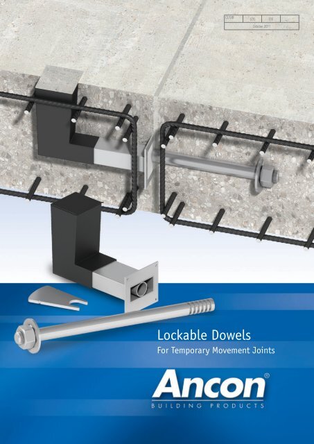
CI/SfB(29) Et6October 2011<strong>Lockable</strong> <strong>Dowels</strong>For Temporary Movement Joints
<strong>Ancon</strong> <strong>Lockable</strong> <strong>Dowels</strong>ContentsAdvantages and Applications 2-3Range of <strong>Lockable</strong> <strong>Dowels</strong> 4-5Performance Data 6Edge Distance and Spacings 7Reinforcement Details 8Dimensions 9Installation 10Projects 11Other <strong>Ancon</strong> <strong>Products</strong> 11LOCKABLE DOWELS<strong>Lockable</strong> <strong>Dowels</strong> have been designed by<strong>Ancon</strong> for use at temporary movement joints,most commonly found in post-tensionedconcrete frames.These dowels allow initial shrinkage of theconcrete to take place and are then locked inposition with a mechanical plate and acontrolled amount of epoxy resin. The lockeddowels continue to transfer shear, but preventfurther movement taking place.ADVANTAGESThe use of <strong>Lockable</strong> <strong>Dowels</strong> can save asignificant amount of time and materialsover other construction methods. Concreteshrinkage has traditionally beenaccommodated by leaving gaps in the slabcalled ‘pour strips’ or ‘closure strips’. Thesestrips are filled once movement has stabilised,however until they are filled the slabs must bepropped, restricting site access and delayingsite progress. Gaps in the slab also create atrip hazard for site workers, use additionalformwork and can leave the soffit face marked.<strong>Lockable</strong> <strong>Dowels</strong> improve site access,minimise formwork requirements andaccelerate the rate of construction. With a<strong>Lockable</strong> Dowel, there is less requirement forthe slabs to be propped or a support corbel tobe constructed, as shear load is transferred bythe dowel. The time saved by early removal ofslab props can be significant.A <strong>Lockable</strong> Dowel also provides manyadvantages over the site-assembledarrangement of carbon steel reinforcing bar,galvanised or plastic ducting, vent tubes and anon-specific grout, which is sometimes usedby contractors.The performance of site assembledsystems can be unreliableIn addition, engineers have found the <strong>Ancon</strong><strong>Lockable</strong> Dowel to be the preferred designsolution for pin-ended joints. Although it iscustomary for practical reasons to use U-barsor other rebar continuity systems at theseconnections, these options do not truly act ashinges and so rotation of the slab under loadcan induce cracking at the wall-to-slabinterface with potential integrity issues.The <strong>Lockable</strong> Dowel is closer to a true pinendedjoint and, being manufactured fromstainless steel, provides additional corrosionprotection over systems using carbon steelreinforcement.Pour Strips restrict site access, cause atrip hazard and delay progress on siteThe design capacities shown on page 6 arebacked by independent test data and theunique void former allows inspection of thedowel before the joint is locked.Standard <strong>Ancon</strong> systems are available for useat slab joints and retaining / core walls.2
Tel: +44 (0) 114 275 5224 Web: www.ancon.co.ukAPPLICATIONSIn most cases, <strong>Ancon</strong> <strong>Lockable</strong> <strong>Dowels</strong> can be used to replace pour strips at temporarymovement joints in post-tensioned concrete frames. Standard <strong>Ancon</strong> systems are availablefor use at slab joints and retaining / core walls.By using these dowels we have saved at least four weeks per storey. Thisconstruction method is just more efficient. Wet trades finish sooner on site andthe anticipated movement at the joints was achieved without any issues.Ben Ume, Director, Matthew ConsultantsUniversity Campus Suffolk phase 2, Ipswich, UKPJ Carey chose the lockable dowel system because it offered time and costsavings, accelerating an already fast build programme.Eamonn O’Donnell, Project Manager, PJ Carey (Contractors) LtdEmergency Care Centre, Aberdeen, UK© P J Carey (Contractors) LimitedEmergency Care Centre, AberdeenSlab-to-Slab✗<strong>Ancon</strong> <strong>Lockable</strong> Dowel✓Proven performanceMinimal material usageVarious site-assembled componentsUnreliable performance, additional constructionmaterials used and support corbel or prop requiredSlab-to-SlabPour strip in slabAdditional formwork,trip hazard andrestricted accessSlabs proppedfor several weeks✗<strong>Ancon</strong> <strong>Lockable</strong> Dowel✓Minimal formworkImproved site accessReduced propping timeSlab-to-Wall✓Restricted accessSlabs proppedfor several weeksPour strip at wall-to-slab junction✗<strong>Ancon</strong> <strong>Lockable</strong> DowelImproved site accessReduced propping time3
<strong>Ancon</strong> <strong>Lockable</strong> <strong>Dowels</strong>RANGE OF LOCKABLE DOWELSA <strong>Lockable</strong> Dowel allows initial shrinkage of the concrete to take place and then, after apre-determined time period (generally 3-4 weeks), is locked in position with a mechanical plateand a controlled amount of epoxy resin. The range comprises three products; ESDQ-L20,HLDQ-L30 and ESDQ-L20W.SLAB-TO-SLAB LOCKABLE DOWELSESDQ-L20*The dowel component is manufactured from30mm diameter stainless steel; one end isthreaded with a fixed nut and washer, and theother features a series of grooves to acceptthe Locking Plate. The cylindrical sleeve whichaccepts the dowel component is containedwithin a box-section to allow lateral,longitudinal and some rotational movement.The epoxy resin is poured into the L-shapedvoid former. This product has a designcapacity of almost 70kN. See pages 6-9 forfull technical details.ESDQ-L20for Slab-to-SlabLocking Plate(notches indicateminimum resin depth)Two-part Epoxy ResinSleeve Component featuringvoid former supplied with labelon nailing plateDowel ComponentLocking Plate(notches indicateminimum resin depth)Two-part Epoxy ResinSleeve Component featuringvoid former supplied with labelon nailing plateReinforcement being located aroundESDQ-L20 SleevesHLDQ-L30*The HLDQ-L30 is a high load <strong>Lockable</strong> Dowelwith a design capacity of up to 136kN. Seepages 6-9 for full technical details.HLDQ-L30for Slab-to-SlabDowel Component* Patent pendingExample Specification ClauseDelete/Amend blue text as appropriate lockable shear load connector comprising dowel,sleeve and locking components to be installed at the temporary movement joint between twoslabs. Product to be positioned at mm horizontal centres at . The dowel is to be locked in position after using the locking plate and resin supplied. System should be installed inaccordance with <strong>Ancon</strong>’s instructions and engineer’s drawings.HLDQ-L30 Sleeve nailed to formwork4
Tel: +44 (0) 114 275 5224 Web: www.ancon.co.ukSLAB-TO-WALL LOCKABLE DOWELESDQ-L20W*The dowel component is manufactured from30mm diameter stainless steel, but is shorterthan the ESDQ-L20 dowel. One end of thedowel is designed to fix into the stainless steel<strong>Ancon</strong> SKS24 Threaded Anchor cast into theface of the concrete and the other endfeatures a series of grooves to accept theLocking Plate. The sleeve component is thesame as used in the ESDQ-L20. See pages6-9 for full technical details.ESDQ-L20Wfor Slab-to-WallLocking Plate(notches indicateminimum resin depth)Two-part Epoxy ResinSleeve Component featuringvoid former supplied with labelon nailing plateDowel ComponentSKS24 Threaded Anchorsupplied with a nailing plate* Patent pendingSleeve pushed over dowel component atcore wallExample Specification ClauseDelete/Amend blue text as appropriate<strong>Ancon</strong> ESDQ-L20W lockable shear loadconnector comprising dowel, sleeve,threaded anchor and locking componentsto be installed at the temporary movementjoint between slab and wall. Product to bepositioned at mmhorizontal centres at .The dowel is to be locked in position after using the lockingplate and resin supplied. System should beinstalled in accordance with <strong>Ancon</strong>’sinstructions and engineer’s drawings.Void formers shown at Slab-to-Wall jointEpoxy ResinEach dowel is locked after a pre-determinedtime period (generally 3-4 weeks) with a highquality, two-part epoxy resin. The resin ismixed and poured into the L-shaped voidformer. Each dowel requires 1,500g of resinwhich can be supplied either in a single can forone application or a greater mass for lockingmultiple dowels.Slab-to-Wall Application5
<strong>Ancon</strong> <strong>Lockable</strong> <strong>Dowels</strong>PERFORMANCE DATAMovementVertical load transferbetween slabsMovement +/-20.5mmLockedVertical load transferbetween slabsLoad transferbetween slabsLockedESDQ-L20 <strong>Lockable</strong> <strong>Dowels</strong> (slab-to-slab)Slab Tension along Vertical Design Resistance (kN) for Various Design JointThickness line of dowel Widths (mm) in C30/37 Concrete(mm) (kN) 5 10 15 20 25 30 35 40160 45 12.0 12.0 12.0 12.0 12.0 12.0 12.0 12.0180 65 25.0 25.0 25.0 25.0 25.0 25.0 25.0 25.0200 80 40.0 40.0 40.0 40.0 40.0 40.0 40.0 40.0220 100 53.6 53.6 53.6 53.6 53.6 53.6 53.6 52.7240 100 62.2 62.2 62.2 62.2 60.6 57.8 55.2 52.7260 and above 100 71.4 69.9 66.6 63.5 60.6 57.8 55.2 52.7ESDQ-L20W <strong>Lockable</strong> <strong>Dowels</strong> (slab-to-wall)Slab Tension along Vertical Design Resistance (kN) for Various Design JointThickness line of dowel Widths (mm) in C30/37 Concrete(mm) (kN) 5 10 15 20 25 30 35 40160 45 12.0 12.0 12.0 12.0 12.0 12.0 12.0 12.0180 65 25.0 25.0 25.0 25.0 25.0 25.0 25.0 25.0200 80 40.0 40.0 40.0 40.0 40.0 40.0 40.0 40.0220 80 53.6 53.6 53.6 53.6 53.6 53.6 53.6 52.7240 80 62.2 62.2 62.2 62.2 60.6 57.8 55.2 52.7260 and above 80 71.4 69.9 66.6 63.5 60.6 57.8 55.2 52.7HLDQ-L30 <strong>Lockable</strong> <strong>Dowels</strong> (slab-to-slab)Slab Tension along Vertical Design Resistance (kN) for Various Design JointThickness line of dowel Widths (mm) in C30/37 Concrete(mm) (kN) 5 10 15 20 25 30 35 40240 and above 100 136.0 136.0 136.0 136.0 136.0 136.0 136.0 121.96ESDQ-L20 ExampleSlab thickness= 240mmJoint width= 20mmConcrete strength = C30/37Characteristic permanent action (dead load) = 40kN/m γ G= 1.35*Characteristic variable action (imposed load) = 50kN/m γ Q= 1.5*Design load= 1.35 x 40 + 1.5 x 50 = 129kN/mVertical design resistanceTherefore centres for vertical load= 62.2kN (240mm slab 20mm joint)= 62.2 / 129 = 0.482m use 450mm centresEach dowel will in addition provide a design resistance across the joint of 100kN (for slab towall this is 80kN), therefore the total design resistance in the direction of the dowel = 100 /0.45 = 222kN (for slab to wall 80 / 0.45 = 177kN).If this is insufficient, the dowel centres can be reduced to a minimum of 1.5 x slab thicknessto increase the design resistance across the joint, in this example it would increase to 100 /0.36 = 277kN (for slab to wall 80 / 0.36 = 222kN).*The partial safety factors of 1.35 (γ G) and 1.5 (γ Q) are those recommended in EN 1990 Eurocode: Basis forstructural design. For designs to Eurocode 2, please refer to the national annex for the factors to be used in thecountry concerned. For designs to BS8110, γ G= 1.4 and γ Q= 1.6. Other national standards may requiredifferent safety factors.Joint Filler / Fire Protection<strong>Ancon</strong> can provide information on a suitablejoint filler and also recommend fire resistantmaterial which could be used as part of anoverall fire protection system.
Tel: +44 (0) 114 275 5224 Web: www.ancon.co.ukEDGE DISTANCE AND SPACINGSFor connectors working at or near their maximum capacity, the minimumspacing should be 1.5 times the slab thickness. Where the design load of the connector could beused in a thinner slab, a spacing of 1.5 times the thinner slab thickness can be used. The minimumend distance is always 0.5 times the spacing.hmin. 0.75h min. 1.5hESDQ-L20 Minimum Edge Distance and Spacings240mmmin.180 min. 360 min.HLDQ-L30 Minimum Edge Distance and Spacings0.75h 1.5hESDQ-L20W Minimum Edge Distance and Spacings. h = depth of adjoining slabESDQ-L20 ExampleSlab thickness= 300mmJoint width= 20mmConcrete strength = C30/37Design resistance/connector= 63.5kN(based on slabs 260mm and above)Spacing for max. load300 x 1.5 = 450mmEnd distance for max. load450 x 0.5 = 225mmDesign resistance/metre= 63.5 / 0.45 = 141.1kN/mAs an ESDQ-L20 can be used in a 220mm slab for a design resistance per connector of upto 53.6kN, the spacing can be based on a 220mm slab. Therefore:Reduced spacingReduced end distanceDesign resistance/metre220 x 1.5 = 330mm330 x 0.5 = 165mm53.6 / 0.33 = 162.4kN/m7
<strong>Ancon</strong> <strong>Lockable</strong> <strong>Dowels</strong>REINFORCEMENT DETAILSLocal reinforcement is required around each <strong>Ancon</strong> <strong>Lockable</strong> Dowel to guarantee that the forces are transferred between the connectors and theconcrete. Correct detailing in accordance with appropriate design codes and the recommendations provided here will ensure the dowels attain theirfull capacity. The tables show the main reinforcement required, together with details of reinforcement above and below the connectors. Although onlythe sleeve components are illustrated, the same reinforcement is required around the dowel component.Options for Main Reinforcement<strong>Lockable</strong> Dowel No. of U-bars each sideRef. H12 H14 H16ESDQ-L20 2 - -HLDQ-L30 4 3 3ESDQ-L20LongitudinalreinforcementaboveOptions for Longitudinal Reinforcement<strong>Lockable</strong> Dowel No. of bars top and bottomRef. H12 H14 H16ESDQ-L20 2 - -HLDQ-L30 2 2 2LongitudinalreinforcementbelowLongitudinalreinforcementaboveMainreinforcementeach sideMain reinforcementeach sideLongitudinalreinforcementbelowHLDQ-L30LongitudinalreinforcementaboveESDQ-L20LongitudinalreinforcementbelowMainreinforcementeach sideLongitudinalreinforcementaboveMain reinforcementeach sideLongitudinalreinforcementbelowHLDQ-L30Threaded AnchorReinforcement around the <strong>Ancon</strong> Threaded Anchor should be a minimum diameter of12mm, installed at maximum 200mm vertical and horizontal centres.8SKS24 Threaded Anchor, part of ESDQ-L20W
Tel: +44 (0) 114 275 5224 Web: www.ancon.co.ukHLDQ-L30 Sleeve ComponentDIMENSIONSESDQ-L20 ComponentsDowel ComponentSleeve Component30mm31mm InternalDiameter170mmMax. +/-20.5mmlateral movement100mm450mm240mm110mmHLDQ-L30 ComponentsDowel ComponentSleeve Component140mm30mm31mm internaldiameter170mmMax. +/-20.5mmlateral movement140mm115mm270mm490mm280mm12mm161mm12mmESDQ-L20W ComponentsSKS24 Threaded AnchorDowel ComponentSleeve Component150mm40mm91mm103mm30mm31mm internaldiameter170mmMax. +/-20.5mmlateral movement100mmM30x3.5mm270mm240mm110mm9
<strong>Ancon</strong> <strong>Lockable</strong> <strong>Dowels</strong>INSTALLATIONSlab-to-SlabAlthough installation is shown for the ESDQ-L20, the procedure is the same for the HLDQ-L30.1 23Nail the sleeve to the formwork either central inthe slab or for slab depths over 300mm so thetop of the void former is level with the top of theslab. Do not remove the label over the nailingplate as this prevents ingress of concrete intothe sleeve. Fix the local reinforcement, asspecified on engineer’s drawings.4Pour the concrete, and when of sufficientstrength, strike the formwork. Puncture thelabel to reveal the cylindrical sleeve only andinsert the dowel until it is approximately 20mmfrom the back of the void former.5Fix the local reinforcement around the dowelcomponent and pour the concrete.6After a predetermined time period (generally 3-4 weeks), when movement between the slabshas stabilised and the joint between the slabshas been filled, the dowel is ready to belocked.Fit the Locking Plate on a groove in the centreof the void former. The fan-shaped LockingPlate allows the dowel to be locked in anyposition.Slab-to-WallMix the two-part epoxy resin and pour into thevoid former. It is essential the resin flows alongthe stainless steel box section towards thejoint and reaches the notches on the lockingplate, which indicate minimum resin depth.Joint must be filled before resin is installed.After 24 hours the void former can be filledwith cementitious material, level with the top ofthe slab, to complete the installation.The locked dowel continues to transfer verticalload between the slabs, but movement can nolonger take place.1 23Nail the threaded anchor to the formwork sothe dowel will be central in the adjoining slabor within 150mm of the top of slabs over300mm. Fix the local reinforcement asspecified on engineer’s drawings and cast theconcrete.When concrete reaches sufficient strength,strike the formwork and remove nailing plate.Screw the dowel into the anchor.Puncture the label of the sleeve to reveal thecylindrical sleeve only. Push the sleeve over thedowel until it is flush with the concrete. Tiesleeve to reinforcement and pour concrete.See Steps 4 to 6 above to completeinstallation.Notes: Where deep concrete pours are proposed, the installation will require further consideration. More robust fixing of the sleeve and dowelcomponents will be necessary, to avoid displacement during casting of the concrete.10
Tel: +44 (0) 114 275 5224 Web: www.ancon.co.ukPROJECT REFERENCES200 <strong>Lockable</strong> dowels were installed on theJames Hehir <strong>Building</strong> (University CampusSuffolk phase 2) in Ipswich, UK‘Highly Commended’ in the 2010CONSTRUCT award for innovation andbest practice for its use of the <strong>Lockable</strong>Dowel.5,000 <strong>Lockable</strong> dowels were installed onthe Royal Children’s Hospital inMelbourne, Australia500 <strong>Lockable</strong> dowels were installed on theEmergency Care Centre in Aberdeen, UK© P J Carey (Contractors) LimitedOTHER ANCON PRODUCTSDSD/Q Shear Load Connectors<strong>Ancon</strong> DSD and DSDQ double-dowelconnectors are used to transfer shear acrossmovement joints in suspended concrete slabs.They are more effective at transferring loadand allowing movement than standard singledowels and can be used to eliminate doublecolumns at structural movement joints inbuildings. The Q version features a rectangularbox section to allow lateral and some rotationalmovement.Plate Dowel Systems<strong>Ancon</strong> MultiJoint is a plate dowel system foruse in ground bearing concrete floor slabs. It isan all-in-one solution to load transfer, concretecontraction, armoured edge protection andformwork. Individual plate dowels are alsoavailable.Punching Shear Reinforcement<strong>Ancon</strong> Shearfix is used within a slab to provideadditional reinforcement from punching sheararound columns. The system consists ofdouble-headed steel studs welded to flat railsand is designed to suit the load conditions andslab depth at each column using freecalculation software from <strong>Ancon</strong>.Reinforcing Bar CouplersThe use of reinforcing bar couplers canprovide significant advantages over lappedjoints. Design and construction of the concretecan be simplified and the amount ofreinforcement can be reduced. The <strong>Ancon</strong>range includes parallel-threaded, taperedthreadedand mechanically-bolted couplers.Reinforcing Continuity Systems<strong>Ancon</strong> Eazistrip is approved by UK CARESand consists of bent bars housed in agalvanised steel casing. Once installed, theprotective cover is removed and the barsstraightened ready for joining. As analternative, <strong>Ancon</strong> Starter Bars are rebarlengths supplied fixed to an <strong>Ancon</strong> couplerwhich can be cast into the face of theconcrete.Insulated Balcony Connections<strong>Ancon</strong> Isolan connectors join external concretebalconies to internal concrete floor slabs.Used to minimise cold bridging, they providecontinuity to the thermal insulation. Standardsystems, comprising rigid CFC-freepolystyrene insulation and duplex stainlesssteel shear reinforcement, suit most depths ofcantilevered and simply supported balconies.Conventional reinforcing bars are used toprovide the tension and compressionreinforcement.11
<strong>Ancon</strong> <strong>Building</strong> <strong>Products</strong>President Way, President ParkSheffield S4 7URUnited KingdomTel: +44 (0) 114 275 5224Fax: +44 (0) 114 276 8543Email: info@ancon.co.ukVisit: www.ancon.co.uk<strong>Ancon</strong> (Middle East) FZEPO Box 17225Jebel AliDubaiUnited Arab EmiratesTel: +971 (0) 4 883 4346Fax: +971 (0) 4 883 4347Email: info@ancon.aeVisit: www.ancon.ae<strong>Ancon</strong> <strong>Building</strong> <strong>Products</strong>114 Kurrajong AvenueMount DruittSydneyNSW 2770AustraliaTel: +61 (0) 2 8808 1111Fax: +61 (0) 2 9675 3390Email: info@ancon.com.auVisit: www.ancon.com.au<strong>Ancon</strong> (Schweiz) AGGewerbezone Widalmi 103216 Ried bei KerzersSwitzerlandTel: +41 (0) 31 750 3030Fax: +41 (0) 31 750 3033Email: info@ancon.chVisit: www.ancon.ch<strong>Ancon</strong> <strong>Building</strong> <strong>Products</strong> GesmbHGerspergasse 9/3 Top 1A-1210 ViennaAustriaTel: +43 (0) 1 259 58 62-0Fax: +43 (0) 1 259 58 62-40Email: info@ancon.atVisit: www.ancon.at<strong>Ancon</strong> GmbHBartholomäusstrasse 2690489 NurembergGermanyTel: +49 (0) 911 955 1234 0Fax: +49 (0) 911 955 1234 9Email: info@anconbp.deVisit: www.anconbp.deThese products are available from:The construction applications and details provided in this literature are indicative only. In every case, projectworking details should be entrusted to appropriately qualified and experienced persons.Whilst every care has been exercised in the preparation of this document to ensure that any advice,recommendations or information is accurate, no liability or responsibility of any kind is accepted in respect of<strong>Ancon</strong> <strong>Building</strong> <strong>Products</strong>.© <strong>Ancon</strong> <strong>Building</strong> <strong>Products</strong> 2011With a policy of continuous product development <strong>Ancon</strong> <strong>Building</strong> <strong>Products</strong> reserves the right to modify productdesign and specification without due notice.ISO 9001: 2008FM 12226ISO 14001: 2004EMS 505377OHSAS 18001: 2007OHS 548992