Bimba Metric Flat Cylinders BIMBA FLAT-1 FITS RIGHT IN!
Bimba Metric Flat Cylinders BIMBA FLAT-1 FITS RIGHT IN!
Bimba Metric Flat Cylinders BIMBA FLAT-1 FITS RIGHT IN!

Create successful ePaper yourself
Turn your PDF publications into a flip-book with our unique Google optimized e-Paper software.
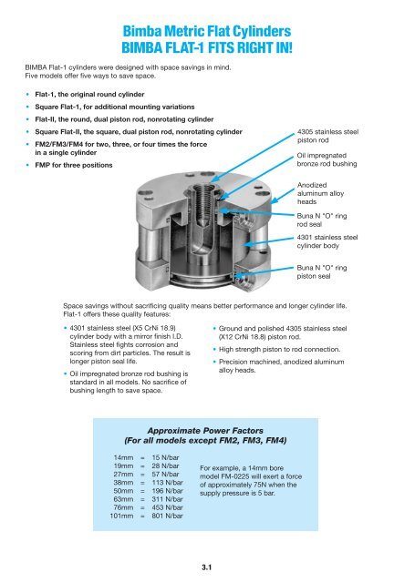
<strong>Bimba</strong> <strong>Flat</strong>-1 <strong>Cylinders</strong><strong>Metric</strong>• Body — 4301 Stainless Steel• Heads — Anodized Aluminum Alloy• Piston Rod — Ground and Polished 4305 Stainless Steel• Seals — Buna N (High temperature seals optional)• Rod Bushing — Oil Impregnated Bronze• Spring Forces — See Page 3.7• Pressure Rating — 14 Bar Maximum (Air only)• Temperature Rating — From -25°C to +65°CBuna N seals with a temperature range of -25°C to +65°C arestandard in all <strong>Bimba</strong> air cylinders. Fluoroelastomer seals rated forhigher temperature applications are available. If cylinders are operatedbelow -18°C for extended time periods, special modificationsmay be required. Special seal materials are available upon request.How to OrderThe Model Number for all <strong>Flat</strong>-1 cylinders consists of three alphanumeric clusters. These designate type,bore size and stroke length, and mounting and special options. Please refer to the charts below for anexample of Model Number FM-1715-3V. This is a double acting, 38mm bore, 15mm stroke cylinder withthreaded mounting holes both ends and high temperature option.TYPEFM - Double Acting, Single End RodFMD - Double Acting, Double End RodFMR - Reverse ActingFMS - Single ActingBORE SIZE02 - 14mm 31 - 50mm04 - 19mm 50 - 63mm09 - 27mm 70 - 76mm17 - 38mm 125 - 101mmSTROKE LENGTH5 - 5mm40 - 40mm100 - 100mmETC.FM-1715-3VOPTIONSMOUNT<strong>IN</strong>G OPTIONS(Enter in numeric order)No Number - Basic model1 - Pivot mount1N - Pivot mount 90° from standard2F* - Front trunnion mount2R* - Rear trunnion mount3 - Threaded mounting holes, both ends3F - Threaded mounting holes, front3R - Threaded mounting holes, rear4 - Screw clearance holes, both ends4F - Screw clearance holes, front4R - Screw clearance holes, rear5 - Nose Mount***Not available in 14mm bore.**Available in FM, FMS and FMR models. Includes heavyduty rear head.(Enter in alphabetical order, except EE which is last)B - Bumpers both ends 2BF - Bumper front 2BR - Bumper rear 2FTF - Fine female thread (see page 3.4)H - Hollow rod (double end modelsonly) (see page 3.7)HD - Heavy duty rear head (see page 3.6)G - Magnalube ® GJ - Failsafe operationMT - Male rod end (coarse thread) (see page 3.7)MTF - Male rod end (fine thread) (see page 3.7)NT - Non-threaded rodP2*, P3, P4* - Front port position #2, etc. (see page 3.3)L - Low friction seals (see page 3.6)M, M1, M3, M4 - Magnetic position sensing (see PositionSensing Solutions, page 7.7) 1Q - Low temperature operation (-40˚C to 95˚C)S - Stainless steel fastenersT1, T3, T4 - Additional switch mounting post located inposition #1, 3 or 4V - High temperature option (-18 to +205°C)W - Rod wiper (Buna N only) (see page 3.7)Y - Moly-coat (MoS 2 I.D. coating)EE10 - 10mm extra rod extension, etc.EE50 - 50mm extra rod extension, etc.*Not available in 14mm bore1If magnetic position sensing is specified with Fluoroelastomer Seals,standard Buna-N based magnet will be provided. Magneticposition sensing is not reliable above 50°C.2Bumpers reduce stroke by 1.5mm per end3.2Magnalube ® is a trademark of Carleton-Stuart Company.
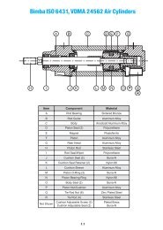
<strong>Metric</strong><strong>Bimba</strong> <strong>Flat</strong>-1 <strong>Cylinders</strong>Model FM(Double Acting,Single End Rod)Standard strokes3.2mm, 5, 10, 15, 20, 25, 30,40, 50, 80, 100mmModel FMD(Double Acting,Double End Rod)Standard strokes3.2mm, 5, 10, 15, 20, 25,30, 40, 50, 80, 100mmModel FMS(Single Acting,Spring Return,Rod Normally Retracted)Standard strokes3.2mm, 5, 10, 15, 20, 25, 30,40, 50mmModel FMR(Reverse Acting,Spring Return,Rod Normally Extended)Standard strokes3.2mm, 5, 10, 15, 20, 25, 30,40, 50mmJTYP.JTYP.3.2 +STROKEJTYP.Basic ModelsB a + STROKEB b + STROKEB C + STROKEKFKTYP.RODDIA.3.2K TYP.3.2FFRODDIA.TYP.RODDIA.3.2C BOLTCIRCLEL PORTDD CLEARHOLES FORD SOCKET HEADCAP SCREWLOCATION OF MTG. HOLES14mm BORE ONLYC BOLTCIRCLEL PORTDD CLEARHOLES FORD SOCKETHEAD CAPSCREWLOCATION OF MTG. HOLES14mm BORE ONLYC BOLTCIRCLEL PORTDD CLEARHOLES FORD SOCKETHEAD CAPSCREWLOCATION OF MTG. HOLES14mm BORE ONLYContact Distributor for price and dimensions over 50mm stroke. See page 3.7 for spring forces.JTYP.B d + STROKEK TYP.FRODDIA.3.2 +STROKEC BOLTCIRCLEL PORTDD CLEARHOLES FORD SOCKETHEAD CAPSCREWLOCATION OF MTG. HOLES14mm BORE ONLYContact Distributor for price and dimensions over 50mm stroke. See page 3.7 for spring forces.11112HE42HE42HE42HE43333AAAAISO 6431 ISO 6432 <strong>Flat</strong> Pneu-Turn Ultran Flow ControlPositionSensing Solutions3.3
<strong>Bimba</strong> <strong>Flat</strong>-1 <strong>Cylinders</strong><strong>Metric</strong>Dimensions(mm)(Basic Model)Bore A Ba* Bb*Bc*Bd*0-25mm 26-50mm 0-25mm 26-55mmC DD D E Std.14mm (02) 28.5 14.3 17.4 20.6 34.9 27.0 41.3 22.5 2 M3 M419mm (04) 38.0 14.3 17.4 20.6 34.9 27.0 41.3 31.0 4 M3 M527mm (09) 50.6 22.2 23.8 22.2 38.1 34.9 50.8 43.0 4 M3 M838mm (17) 66.4 22.2 25.4 22.2 38.1 34.9 50.8 56.0 4 M5 M1050mm (31) 79.1 23.8 27.0 23.8 39.7 36.5 52.4 68.0 4 M5 M1263mm (50) 95.0 30.2 33.3 30.2 52.4 49.2 88.9 83.0 4 M6 M1276mm (70) 107.7 31.8 34.9 31.8 54.0 50.8 73.0 96.0 4 M6 M16101mm (125) 139.5 39.7 42.9 39.7 61.9 58.7 81.0 125.0 4 M8 M20Bore E Fine E Depth F H J K L14mm (02) M4x0.5 11.7 6.3 5.5 8.7 3.6 M519mm (04) M5x0.5 11.7 7.9 6.0 8.7 3.6 M527mm (09) M8x1.0 17.8 12.7 11.0 12.7 6.4 G 1/838mm (17) M10x1.25 17.8 15.9 12.0 12.7 6.4 G 1/850mm (31) M12x1.25 17.8 19.1 16.0 13.5 6.4 G 1/863mm (50) M12x1.25 17.8 19.1 16.0 16.7 8.3 G 1/876mm (70) M16x1.5 18.5 22.2 19.0 17.5 8.3 G 1/8101mm (125) M20x1.5 20.3 25.4 22.0 21.4 10.7 G 1/4*See page 3.6 for length adders for options.3.4
<strong>Metric</strong><strong>Bimba</strong> <strong>Flat</strong>-1 <strong>Cylinders</strong>Trunnion Mount(rear or front)(-2F shown)Not available in 14mm bore.PThreaded Mounting Holes(available either or both ends)(-3R shown)14mm BoreC90ºTYP.BOLT CIRCLENMMounting OptionsPD-DR HOLESLOCATION OF MTG. HOLES14mm BORE ONLYTHREADEDNose Mount(available in FM, FMS, FMR)(-5 shown)Includes heavy duty rear head; see page 3.6Pivot Mount(-1 shown)Complete with bronze pivot bushing.Not available as an accessory.19mm Bore and larger*4 THREADEDR HOLESC BOLTCIRCLE90°TYP.*43º-19mm Bore only 45º-all other boresScrew Clearance Holes(available either or both ends)(-4R shown)ISO 6431 ISO 6432 <strong>Flat</strong> Pneu-Turn Ultran Flow ControlAAAFABACAE3.2ADXPositionSensing Solutions3.5
<strong>Metric</strong><strong>Bimba</strong> <strong>Flat</strong>-1 <strong>Cylinders</strong>Rod Wiper (Option W)BoreWD14mm (02) 14.319mm (04) 17.527mm (09) 22.238mm (17) 25.450mm (31)63mm (50)28.676mm (70) 31.8101mm (125) 34.94.8WD9.5Options(mm)FMD Hollow Rods (Option H)BoreEnclosed Spring ForcesMale Rod Ends (Option MT or MTF)BoreMTEMTFLGETHREADLG14mm (02) M4 M4 x 0.5 1019mm (04) M5 M5 x 0.5 1027mm (09) M8 M8 x 1.0 1238mm (17) M10 M10 x 1.25 1250mm (31)63mm (50)M12 M12 x 1.25 1676mm (70) M16 M16 x 1.5 20101mm (125) M20 M20 x 1.5 20FemaleRod ThreadsHole DiameterMaleRod Threads14mm (02) 3.2 N/A19mm (04) 3.6 2.427mm (09) 5.6 4.038mm (17) 7.1 4.850mm (31)63mm (50)9.5 6.476mm (70) 11.1 7.9101mm (125) 12.7 9.5BoreMaximumLoad1-25mmstrokeSpring Rate26-50mmstroke14mm (02) 25N .74 N/mm .30 N/mm19mm (04) 45N 1.05 N/mm .44 N/mm27mm (09) 50N 1.05 N/mm .44 N/mm38mm (17)50mm (31)63mm (50)76mm (70)101mm (125)57N .95 N/mm .39 N/mm110N 1.13 N/mm .48 N/mmISO 6431 ISO 6432 <strong>Flat</strong> Pneu-Turn Ultran Flow ControlPositionSensing Solutions3.7
<strong>Bimba</strong> <strong>Flat</strong>-1 <strong>Cylinders</strong><strong>Metric</strong>Repair PartsSingle End Rod KitsBasic Repair Kit (K-B-FO)*Part No. Description QuantityPF-1 Rod Seal 1PF-2 Piston Seal 1PF-3 Tube Seal 2PF-4 Bushing 2Wiper Option Basic Repair Kit (K-B-FO-W)*Part No. Description QuantityPF-1 Rod Seal 1PF-2 Piston Seal 1PF-3 Tube Seal 2PF-4 Bushing 1PF-5 Wiper Bushing 1PF-6 Wiper 1Double End Rod KitsBasic Repair Kit (K-B-FOD)*Part No. Description QuantityPF-1 Rod Seal 2PF-2 Piston Seal 1PF-3 Tube Seal 2PF-4 Bushing 2Wiper Option Basic Repair Kit (K-B-FOD-W)*Part No. Description QuantityPF-1 Rod Seal 2PF-2 Piston Seal 1PF-3 Tube Seal 2PF-5 Wiper Bushing 2PF-6 Wiper 2*Must specify bore size when ordered. Contact your local<strong>BIMBA</strong> Distributor for pricing on kits and other repair parts.Single End Rod Kits for Nose Mount OptionBasic Repair Kit (K-B-FO-N)Part No. Description QuantityPF-1 Rod Seal 1PF-2 Piston Seal 1PF-3 Tube Seal 2PF-4 Bushing 2WiperD-63632 14mm (02) 1D-63633 19mm (04) 1D-63634 27mm (09) 1D-63635 38mm (17) 1D-63636 50mm (31), 63mm (50) 1D-63637 76mm (70) 1D-63638 101mm (125) 1Mounting NutsBorePart No.14mm (02) D-6275219mm (04) D-6275327mm (09) D-6275438mm (17) D-6275550mm (31) D-6275663mm (50) D-6275676mm (70) D-62785101mm (125) D-62785BoreBaseApproximate Cylinder Weights (gms)FM, FMS FMD FMR Nose Mount optionAdderper 5mmof strokeBaseWeightsAdderper 5mmof stroke3.8Adder per5mm ofstroke for-H optionBaseAdderper 5mmof strokeAdder to baseweight14mm (02) 34 3.6 37 6.8 4.4 36.9 3.6 519mm (04) 54 4.4 60 9 6.8 56.7 4.4 1027mm (09) 139 13.4 164 17.8 13.4 150.3 13.4 4038mm (17) 272 17.8 318 26.7 22.3 297.7 17.8 7050mm (31) 369 22.3 431 31.1 26.7 396.9 22.3 12063mm (50) 635 26.7 794 35.5 31.1 708.7 26.7 13076mm (70) 819 35.5 1077 49 40.1 921.4 35.5 180101mm (125) 1579 44.6 2036 58 49 1752.0 44.6 210
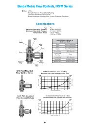
<strong>Metric</strong><strong>Bimba</strong> Square <strong>Flat</strong>-1 <strong>Cylinders</strong>The convenient alternative for horizontal and side mounting, with provisionsfor both a bottom flush or face mounting. The Square <strong>Flat</strong>-1 also minimizesthe centerline distance when cylinders are mounted side-by-side.• Body — 4301 Stainless Steel• Heads — Anodized Aluminum Alloy• Piston Rod — Ground and Polished 4305 Stainless Steel• Seals — Buna N (High temperature seals optional)• Rod Bushing — Oil Impregnated Bronze• Tie Rods — 4305 Stainless Steel• Spring Forces — See Page 3.13• Pressure Rating — Bore Sizes 19mm-50mm 14 Bar Maximum (Air only)Bore Sizes 63mm-101mm 10.34 Bar Maximum (Air only)• Temperature Rating — From -25°C to +65°C. Buna N seals with atemperature range of -25°C to +65°C are standard in all <strong>Bimba</strong> aircylinders. Fluoroelastomer seals rated for higher temperature applicationsare available. If cylinders are operated below -18°C for extendedtime periods, special modifications may be required. Special sealmaterials are available upon request.The Model Number for all Square <strong>Flat</strong>-1 cylinders consists of three alphanumeric clusters. These designate type,bore size and stroke length, and options. Please refer to the charts below for an example of Model NumberFSMS-7040-V. This is a single acting, 76mm bore, 40mm stroke cylinder with high temperature option.TYPEFSM - Double Acting, Single End RodFSMD - Double Acting, Double End RodFSMR - Reverse ActingFSMS - Single ActingHow to Order04 - 19mm09 - 27mm17 - 38mm31 - 50mmBORE SIZE50 - 63mm70 - 76mm125 - 101mmFSMS-7040-VOPTIONS(Enter in alphabetical order, except EE which is last)B - Bumpers both ends 2BF - Bumper front 2BR - Bumper rear 2FTF - Fine female thread (see page 3.11)G - Magnalube ® GJ - Failsafe operationH - Hollow rod (double end models only)(see page 3.13)L - Low friction seals (see page 3.12)M, M1, M4 - Magnetic position sensing (see Position SensingSolutions, page 7.7) 1MT - Male rod end (coarse thread) (see page 3.12)MTF - Male rod end (fine thread) (see page 3.12)NT - Non-threaded rodQ - Low temperature operation (-40˚C to 95˚C)S - Stainless steel fastenersT1, T4 - Additional switch track located in position #1 or 4V - High temperature option (-18 to +205°C)W - Rod wiper (Buna N only) (see page 3.12)Y - Moly-coat (MoS 2 I.D. coating)EE10 - 10mm extra rod extension, etc.EE50 - 50mm extra rod extension, etc.1If magnetic position sensing is specified with Fluoroelastomer Seals,standard Buna-N based magnet will be provided. Magnetic positionsensing is not reliable above 50°C.2Bumpers reduce stroke by 1.5mm per endSTROKE LENGTH5 - 5mm40 - 40mm100 - 100mmETC.ISO 6431 ISO 6432 <strong>Flat</strong> Pneu-Turn Ultran Flow ControlPositionSensing SolutionsMagnalube ® is a trademark of Carleton-Stuart Company.3.9
<strong>Metric</strong><strong>Bimba</strong> Square <strong>Flat</strong>-1 <strong>Cylinders</strong>Model FSMS(Continued)Model FSMR(Reverse Acting,Spring Return, RodNormally Extended)Standard strokes3.2mm, 5, 10, 15, 20,25, 30, 40, 50mmContact Distributor for priceand dimensions over 50mmstroke. See page 3.13 forspring forces.*For C and DD dimensionswith – M option, see page3.20.Bore sizes63mm, 76mm,101mmBore Aw Ah Ba*C*TYP.Bore sizes19mm, 27mm,38mm, 50mmBore sizes63mm, 76mm,101mmLPORTC TYPLPORTC TYPC*TYP.C*TYP.LLLLBasic ModelsCTYP.C*TYP.CTYP.Dimensions(mm)Bc*CTYP.CTYP.LLLPORTCTYP.CTYP.DD* -2 PLACESEACH ENDDD -4 PLACESEACH ENDBd*0-25mm 26-50mm 0-25mm 26-50mmDD - 4 PLACESC CA DD19mm (04) N/A 31.8 19.0 25.4 39.7 31.8 46.0 10.0 7.0 M4 x 0.727mm (09) N/A 38.1 31.8 31.8 47.6 44.4 60.3 12.5 9.4 M4 x 0.738mm (17) N/A 50.8 31.8 31.8 47.6 44.4 60.3 18.0 7.9 M5 x 0.850mm (31) N/A 63.5 33.4 33.4 49.2 46.0 61.9 22.0 9.7 M6 x 1.063mm (50) 83.3 82.6 42.2 42.2 64.5 60.7 83.1 30.0 10.7 M8 x 1.2576mm (70) 96.0 95.3 43.4 43.4 65.5 62.0 84.1 36.5 11.1 M8 x 1.25101mm (125) 128.0 127.0 50.8 50.8 73.2 69.8 92.0 46.0 12.7 M12 x 1.75KTYP.CADD -4 PLACESEACH ENDJKTYP.KTYP.CACABd + STROKEJJBc + STROKEGBd + STROKEGGCACA3.2F ROD DIA.CA3.2 +STROKEF RODDIA.3.2 +STROKEF ROD DIA.EDD -4 PLACESEDD -4 PLACESEHHHAwAwLLA SQ.LLLLLPORTLPORTAhAhLPORTISO 6431 ISO 6432 <strong>Flat</strong> Pneu-Turn Ultran Flow ControlBore E Standard E Fine E Depth F G H J K L LL19mm (04) M5 x 0.8 M5 x 0.5 11.7 7.9 10.7 6.0 10.7 3.6 M5 7.527mm (09) M8 x 1.25 M8 x 1.0 17.8 12.7 14.9 11.0 12.7 6.4 G 1/8 12.838mm (17) M10 x 1.5 M10 x 1.25 17.8 15.9 14.6 12.0 12.7 6.4 G 1/8 17.550mm (31) M12 x 1.75 M12 x 1.25 17.8 19.1 15.7 16.0 15.7 6.4 G 1/8 19.663mm (50) M12 M12 x 1.25 17.8 19.1 21.4 16.0 21.4 10.7 G 1/8 19.776mm (70) M16 M16 x 1.5 18.5 22.2 22.2 19.0 22.2 11.1 G 1/8 24.9101mm (125) M20 M20 x 1.5 20.3 25.4 25.4 22.0 25.4 12.7 G 1/4 31.8* See page 3.12 for length adders for options.PositionSensing Solutions3.11
<strong>Bimba</strong> Square <strong>Flat</strong>-1 <strong>Cylinders</strong><strong>Metric</strong>Options(mm)(Dimensional variations from standard as shown)BoreLow FrictionSeals (L)Length AdderMagnetic PositionSensing* (M)Low Friction Sealsand MagneticPosition Sensing19mm (04) 6.4 19.1 19.127mm (09) 9.5 12.7 12.738mm (17) 9.5 15.9 15.950mm (31) 9.5 15.9 15.963mm (50) 9.5 22.2 22.276mm (70) 12.7 22.2 22.2101mm (125) 12.7 22.2 22.2*A minimum stroke of 9.5mm is required to sense extending end-of-stroke position.Rod Wiper (Option W)(Buna N standard,not available in fluoroelastomer)Male Rod Ends (Option MT or MTF)Bore WD19mm (04) 17.527mm (09) 22.238mm (17) 25.450mm (31) 28.663mm (50) 28.676mm (70) 31.8101mm (125) 34.9EBoreMT MTFLG19mm (04) M5 M5 x 0.5 1027mm (09) M8 M8 x 1.0 1238mm (17) M10 M10 x 1.25 1250mm (31) M12 M12 x 1.25 1663mm (50) M12 M12 x 1.25 1676mm (70) M16 M16 x 1.5 20101mm (125) M20 M20 x 1.5 203.12
<strong>Metric</strong><strong>Bimba</strong> Square <strong>Flat</strong>-1 <strong>Cylinders</strong>Options(mm)FSMD Hollow Rods (Option H)BoreFemaleRod ThreadsHole DiameterMaleRod Threads19mm (04) 3.6 2.427mm (09) 5.6 4.038mm (17) 7.1 4.850mm (31) 9.5 6.463mm (50) 9.5 6.476mm (70) 11.1 7.9101mm (125) 12.7 9.5Enclosed Spring ForcesBoreMaximumLoadSpring Rate1-25mm stroke 26-50mm stroke19mm (04) 45N 1.05 N/mm .44 N/mm27mm (09) 50N 1.05 N/mm .44 N/mm38mm (17)50mm (31)63mm (50)76mm (70)101mm (125)57N 0.95 N/mm .39 N/mm110 N 1.13 N/mm .48 N/mmISO 6431 ISO 6432 <strong>Flat</strong> Pneu-Turn Ultran Flow ControlPositionSensing Solutions3.13
<strong>Bimba</strong> Square <strong>Flat</strong>-1 <strong>Cylinders</strong><strong>Metric</strong>Repair KitsSingle End Rod KitsBasic Repair Kit (K-B-FS)*Part No. Description QuantityPF-1 Rod Seal 1PF-2 Piston Seal 1PF-41 Tube Seal 2PF-4 Bushing 2Double End Rod KitsBasic Repair Kit (K-B-FSD)*Part No. Description QuantityPF-1 Rod Seal 2PF-2 Piston Seal 1PF-41 Tube Seal 2PF-4** Bushing 3Wiper Option Basic Repair Kit(K-B-FS-W)*Part No. Description QuantityPF-1 Rod Seal 1PF-2 Piston Seal 1PF-41 Tube Seal 2PF-4 Bushing 1PF-5 Wiper Bushing 1PF-6 Wiper 1Wiper Option Basic Repair Kit(K-B-FSD-W)*Part No. Description QuantityPF-1 Rod Seal 2PF-2 Piston Seal 1PF-41 Tube Seal 2PF-4** Bushing 1PF-5 Wiper Bushing 2PF-6 Wiper 2*Must specify bore size when ordered. Contact your local <strong>BIMBA</strong> Distributor for pricing on kits and other repair parts.**Note: On FSMD (Double Acting, Double End Rod) models, two bushings are provided on the head end with tie rod nuts.Opposite head end has one bushing.WeightsBoreBaseApproximate Cylinder Weights (gms)FSM, FSMS FSMD FSMRAdder per5mm ofstrokeBaseAdder per5mm ofstrokeAdder per5mm ofstroke for-H optionBaseAdder per5mm ofstroke19mm (04) 62 4.4 68 9 6.8 62 4.427mm (09) 145 9 162 17.8 13.4 155 938mm (17) 286 13.4 298 26.7 22.3 290 13.450mm (31) 403 17.8 454 35.5 26.7 425 17.863mm (50) 809 11.3 968 17 14.2 883 11.376mm (70) 1138 17 1395 25.5 19.8 1240 17101mm (125) 2026 17 2482 25.5 19.8 2199 173.14
<strong>Metric</strong><strong>Bimba</strong> <strong>Flat</strong>-II <strong>Cylinders</strong><strong>Flat</strong>-II nonrotating, double-acting cylinder provides the answer to applicationswhere rotation cannot be tolerated and space is at a minimum. Nonrotation isachieved with dual piston rods and a rod end block that insures the rods workin tandem. <strong>Flat</strong>-II eliminates the need for external alignment devices, such asguides, rods and alignment posts or pins.• Body — 4301 Stainless Steel• Heads — Anodized Aluminum Alloy• Piston Rod — Ground and Polished 4305 Stainless Steel• Piston Seals — Buna N Block V (High temperature seals optional)• Rod Bushing — Oil Impregnated Bronze• Rod Seals — Buna N O-ring (High temperature seals optional)• Tie Rods — 4305 Stainless Steel• Rod End Block — Anodized Aluminum Alloy• Pressure Rating — 14 Bar Maximum (Air only)• Temperature Rating — From -25°C to +65°CBuna N seals with a temperature range of -25°C to +65°C are standard inall <strong>Bimba</strong> air cylinders. Fluoroelastomer seals rated for higher temperatureapplications are available. If cylinders are operated below -18°C forextended time periods, special modifications may be required. Specialseal materials are available upon request.The model number for <strong>Flat</strong>-II consists of three alphanumeric clusters. These designate type, bore size and strokelength, and mounting and special options. Please refer to the charts below for an example of Model NumberFTM-0425-3CE. This is a nonrotating, double-acting, 19mm bore, 25mm stroke cylinder with threaded mountingholes both ends and counterbored mounting holes in the rod end block.FTMTYPE- Nonrotating, Double ActingMOUNT<strong>IN</strong>G OPTIONS(Enter in numeric order)No Number - Basic model1 - Pivot mount1N - Pivot mount 90° from standard2F - Front trunnion mount2R - Rear trunnion mount3 - Threaded mounting holes, both ends3F - Threaded mounting holes, front3R - Threaded mounting holes, rear4 - Screw clearance holes, both ends4F - Screw clearance holes, front4R - Screw clearance holes, rearHow to OrderBORE SIZE04 - 19mm09 - 27mm17 - 38mm31 - 50mmFTM-0425-3 CEOPTIONSSTROKE LENGTH5 - 5mm40 - 40mm100 - 100mmETC.(Enter in alphabetical order, except EE which is last)CE - Counterbored rod end block(see page 3.17)G - Magnalube ® GM, M1, M3, M4 - Magnetic position sensing (see PositionSensing Solutions, page 7.7) 1P3 - Front port position (see page 3.16)Q - Low temperature operation (-40˚C to 95˚C)S - Stainless steel fastenersT1, T3, T4 - Additional switch mounting postlocated in position #1, 3 or 4V - High temperature seals (-18 to +205°C)Y - Moly-coat (MoS 2 I.D. coating)EE10 - 10mm extra rod extension, etc.EE50 - 50mm extra rod extension, etc.1If magnetic position sensing is specified with FluoroelastomerSeals, standard Buna-N based magnet will be provided.Magnetic position sensing is not reliable above 50°C.ISO 6431 ISO 6432 <strong>Flat</strong> Pneu-Turn Ultran Flow ControlPositionSensing Solutions3.15Magnalube ® is a trademark of Carleton-Stuart Company.
<strong>Bimba</strong> <strong>Flat</strong>-II <strong>Cylinders</strong><strong>Metric</strong>Basic ModelModel FTM(Nonrotating, double acting)Standard strokes3.2mm, 5, 10, 15, 20, 25, 30,40, 50, 80, 100mmLonger strokes availableupon requestKKJJJKVL4 CLEARANCEHOLES FORD SOCKET HEADCAP SCREWL PORTA1HC BOLTCIRCLE2RODF DIA.3VH4B + STROKE1.6E THREADED2 PLACESVVTrunnion Mount(rear or front)(-2R shown)NPMounting OptionsPivot Mount(complete with bronze bushing)(-1 shown)PMThreaded Mounting Holes(available either or both ends)(-3R shown)90°TYP.Screw Clearance Holes(available either or both ends)(-4R shown)*X4 THREADEDR HOLESC BOLTCIRCLE*43° 19mm bore only. 45° all other bores.3.16
<strong>Metric</strong><strong>Bimba</strong> <strong>Flat</strong>-II <strong>Cylinders</strong>Counterbored Rod End BlockDimensions(mm)Bore J JJ K KK L M N P Q R19mm (04) 8.7 11.9 3.6 6.8 M5 8 3 4.5 5 M327mm (09) 12.7 17.5 6.4 11.1 G 1/8 13 6 6.5 5 M338mm (17) 12.7 17.5 6.4 11.1 G 1/8 13 6 6.5 10 M550mm (31) 13.5 18.3 6.4 11.1 G 1/8 13 6 6.5 10 M5Bore S T U V VT VL VH W X Y Z19mm (04) 9.5 5 6.5 9.0 9.5 30.0 22.0 19 6 19 527mm (09) 9.5 6.5 6.5 9.0 9.5 37.0 27.0 20.5 6 19 538mm (17) 19 6.5 11.5 12.0 12.7 51.0 38.0 30 9 35 9.550mm (31) 19 8 11 15.0 15.9 64.0 48.0 32 9 35 9.5*Magnetic Position Sensing Length Adder: 15.9mm.A minimum stroke of 9.5mm is required to sense extending end-of-stroke position.1.6Bore A B* C D E EC F H19mm (04) 38.0 23.8 31.0 M3 M3 x 0.5 M3 4.8 8.427mm (09) 50.6 33.3 43.0 M3 M4 x 0.7 M4 6.4 10.738mm (17) 66.4 33.3 56.0 M5 M6 x 1.0 M6 9.5 14.350mm (31) 79.1 34.9 68.0 M5 M8 x 1.25 M8 12.7 19.1VECFORSOCKETHEAD CAPSCREWS(2 PLACES)VHVLISO 6431 ISO 6432 <strong>Flat</strong> Pneu-Turn Ultran Flow ControlPositionSensing Solutions3.17
<strong>Bimba</strong> <strong>Flat</strong>-II <strong>Cylinders</strong><strong>Metric</strong>Nonrotation is achieved through the use of dual piston rods incorporated into the body of the <strong>Flat</strong>-IIcylinder. The rods are securely attached to the piston by our unique spin-riveting process. A rod endblock is used to insure the rods work in tandem—as a team. This end block also acts as a usefulsurface to easily accommodate any mounting attachments required to get the job done. For mountingconvenience, the rod end block is provided with threaded mounting holes or optionalcounterbored holes.As with any cylinder application, side loading should be avoided. The two smaller rods will havemore deflection due to side load than the one standard rod in a comparable <strong>Flat</strong>-1 model.The <strong>Flat</strong>-II is intended to work satisfactorily against pure torsional loads.The maximum torsional load per bore size is shown in the following table:Bore 19mm (04) 27mm (09) 38mm (17) 50mm (31)Torque (cm-kg) 0.35 1.15 5.77 11.55K 85.38 436.06 3914.1 22034The amount of angular deflection, in degrees, can be approximated by the following formula:O =TL 3KWhere T = Torque (Cm.-Kg.)L = Length (see sketch below)K = Per chart aboveO = Angular deflectionNote: To prevent rod distortion, the rod end block must be fastened securely.Rotational ToleranceDeflection L ValueBore Maximum Rotation19mm (04) ±1°27mm (09) ±3/4°38mm (17) ±1/2°50mm (31) ±1/2°LRepair KitsWeightsBasic Repair Kit (K-B-FT)*Part No. Description QuantityPF-29 Rod Seal 2PF-30 Piston Seal 2PF-3 Tube Seal 2PF-31 Bushing 4*Must specify bore size when ordered.Contact your local <strong>BIMBA</strong> Distributor for pricingon kits and other repair parts.3.18
<strong>Metric</strong><strong>Bimba</strong> Square <strong>Flat</strong>-II <strong>Cylinders</strong><strong>Metric</strong> Square <strong>Flat</strong>-II nonrotating, double acting cylinder provides the answer to applications where rotationcannot be tolerated. Nonrotation is achieved with dual piston rods and a rod end block that insures the rods workin tandem. Square <strong>Flat</strong>-II eliminates the need for external alignment devices. It also provides a convenientalternative for horizontal and side mounting, with provisions for both bottom flush or face mounting. Centerlinedistances are minimized, facilitating side-by-side cylinder mounting.TYPE• Body — 4301 Stainless Steel• Heads — Anodized Aluminum Alloy• Piston Rod — Ground and Polished 4305 Stainless Steel• Piston Seals — Enhanced Lubricity Buna N (High temperature seals optional)• Rod Bushing — Bronze• Rod Seals — Buna N Block V (High temperature seals optional)• Tie Rods — 4305 Stainless Steel• Rod End Block — Anodized Aluminum Alloy• Pressure Rating — 14 Bar Maximum (Air only)• Temperature Rating — From -25°C to +65°CBuna N seals with a temperature range of -25°C to +65°C are standard in all<strong>Bimba</strong> air cylinders. Fluoroelastomer seals rated for higher temperatureapplications are available. If cylinders are operated below -18°C for extendedtime periods, special modifications may be required. Special seal materialsare available upon request.How to OrderThe Model Number for all Square <strong>Flat</strong>-II cylinders consists of three alphanumeric clusters. These designate type,bore size and stroke length and special options. Please refer to the charts below for an example of ModelNumber FSTM-1740-V. This is a nonrotating, double acting, 38mm bore, 40mm stroke cylinder, with hightemperature option.BORE SIZEFSTM - Nonrotating, Double Acting 04 - 19mm09 - 27mm17 - 38mm31 - 50mmFSTM-1740-VOPTIONS(Enter in alphabetical order, except EE which is last)CE - Counterbored EndblockG - Magnalube ® GK - Endblock rotated 90 degrees (see page 3.22)L - Low Friction Seals (see page 3.21)M, M1, M4 - Magnetic Position Sensing (see Position SensingSolutions, page 7.7) 1Q - Low temperature operation (-40˚C to 95˚C)S - Stainless steel fastenersT1, T4 - Additional switch track located in position #1 or 4V - High temperature seals (-18°C to 205°C)Y - Moly-coat (MoS 2 I.D. coating)EE10 - 10mm extra rod extension, etc.EE50 - 50mm extra rod extension, etc.1If magnetic position sensing is specified with Fluoroelastomer Seals, standardBuna-N based magnet will be provided. Magnetic position sensing is not reliableabove 50°C.STROKE LENGTH5 - 5mm40 - 40mm100 - 100mmETC.ISO 6431 ISO 6432 <strong>Flat</strong> Pneu-Turn Ultran Flow ControlPositionSensing SolutionsMagnalube ® is a trademark of Carleton-Stuart Company.3.19
<strong>Bimba</strong> Square <strong>Flat</strong>-II <strong>Cylinders</strong><strong>Metric</strong>Basic ModelModel FSTM(Nonrotating, doubleacting)Standard strokes3.2mm, 5, 10, 15, 20, 25,30, 40, 50, 80, 100mmLonger strokes availableupon request*Cand DD dimensions apply toSquare <strong>Flat</strong>-1 models with– M option in 19, 27,38, and 50mm bore sizes).M (TYP)LPORTLLC*C*C* C*#4- 40 UNC - 2B x .141DPSWITCH TRACK MOUNT<strong>IN</strong>GDD* - 3 PLACESJK(TYP)CACAB + STROKEDD - 4 PLACESG.062VHFØ RODA SQ.ETHREADED2 - PLACESCounterbored Rod End BlockEC FORSOCKET HEAD CAPSCREWS (2 - PLACES)VHVL1.6VDimensions (MM)Bore A B C CA DD E EC F G H19mm (04) 31.8 19 10.0 7.0 M4 x 0.7 M3 x 0.5 M3 4.8 10.7 8.427mm (09) 38.1 31.8 12.5 9.4 M4 x 0.7 M4 x 0.7 M4 6.4 14.9 10.738mm (17) 50.8 31.8 18.0 7.9 M5 x 0.8 M6 x 1.0 M6 9.5 14.6 14.350mm (31) 63.5 33.3 22.0 9.7 M6 x 1.0 M8 x 1.25 M8 12.7 15.7 19.1Bore J K L LL M V VH VL19mm (04) 10.7 4.8 M5 8.9 8.9 9.0 22.0 31.027mm (09) 12.7 6.4 G 1/8 10.7 8.2 9.0 27.0 37.038mm (17) 12.7 6.4 G 1/8 15.2 5.1 12.0 38.0 50.050mm (31) 15.7 6.4 G 1/8 19.3 4.7 15.0 48.0 63.0A minimum stroke of 9.5mm is required to sense extending end-of-stroke position.See page 3.21 for length adders for magnet option.3.20
<strong>Metric</strong><strong>Bimba</strong> Square <strong>Flat</strong>-II <strong>Cylinders</strong>Repair KitsBasic Repair Kit (K-B-FSTM)*Part No. Description QuantityPF-29-FSTM Rod Seal 2PF-30-FSTM Piston Seal 1PF-3-FSTM Tube Seal 2BoreLow FrictionSeals (L)BoreOptionsApproximate Cylinder Weights (grams)BaseAdder per 5mmof stroke19mm (04) 76 4.427mm (09) 181 22.338mm (17) 345 31.250mm (31) 467 40.0Length AdderMagnetic PositionSensing* (M)WeightsLow Friction Sealsand MagneticPosition Sensing19mm (04) 6.4 19 1927mm (09) 9.7 12.7 12.738mm (17) 9.7 16 1650mm (31) 9.7 16 16*A minimum stroke of 9.5mm is required to sense extending end-of-stroke position.ISO 6431 ISO 6432 <strong>Flat</strong> Pneu-Turn Ultran Flow ControlPositionSensing Solutions3.21
<strong>Bimba</strong> Square <strong>Flat</strong>-II <strong>Cylinders</strong><strong>Metric</strong>Nonrotation is achieved through the use of dual piston rods incorporated into the body of the <strong>Flat</strong>-IIcylinder. The rods are securely attached to the piston by our unique spin-riveting process. A rod end block isused to insure the rods work in tandem—as a team. This end block also acts as a useful surface to easilyaccommodate any mounting attachments required to get the job done. For mounting convenience, the rod endblock is provided with threaded mounting holes or optional counterbored holes.As with any cylinder application, side loading should be avoided (see option K below). The two smaller rods willhave more deflection due to side load than the one standard rod in a comparable <strong>Flat</strong>-1 model.The <strong>Flat</strong>-II is intended to work satisfactorily against pure torsional loads.The maximum torsional load per bore size is shown in the following table:The amount of angular deflection, in degrees, can be approximated by the following formula:Ø = TL3KWhere T = Torque (Cm.-Kg.)L = Length (see sketch below)K = Per chart aboveØ = Angular deflectionNote: To prevent rod distortion, the rod end block must be fastened securely.Rotational ToleranceBore Maximum Rotation19mm (04) ±1°27mm (09) ±3/4°38mm (17) ±1/2°50mm (31) ±1/2°Deflection L ValueLL = 1.6 + STROKEOption K - Endblock Rotated 90°If side load cannot be avoided,the side load should be appliedperpendicular to the planeformed by the two piston rods.3.22
<strong>Metric</strong><strong>Bimba</strong> FM2, FM3, FM4 <strong>Cylinders</strong>Space-Saving <strong>Cylinders</strong> That Multiply Force OutputThe <strong>Bimba</strong> FM2, FM3, FM4 Series <strong>Flat</strong>-1 are double-acting, singleend rod cylinders that multiply the force output by supplying air tomultiple pistons on extension. They save space and eliminate theneed for a higher pressure system. Only one piston is powered onthe return stroke, saving air volume and operating costs.• Body — 4301 Stainless Steel (X5 CrNi 18.9)• Heads — Anodized Aluminum Alloy• Piston Rod — Ground and Polished 4305 Stainless Steel (X12 CrNi18.8)• Seals — Buna N (High temperature seals optional)• Rod Bushing — Oil Impregnated Bronze• Pressure Rating — 7 Bar Maximum (Air only)• Temperature Rating — From -25°C to +65°CBuna N seals with a temperature range of -25°C to +65°C arestandard in all <strong>Bimba</strong> air cylinders. Fluoroelastomer seals rated forhigher temperature applications are available. If cylinders are operatedbelow -18°C for extended time periods, special modificationsmay be required. Special seal materials are available upon request.How it WorksExtension-air – air supplied to multiple to multiple pistons pistonsAirInletAirExhaustAirExhaustAirDrawn InAirExhaustRetraction-air – air supplied to one to one piston piston only onlyAirDrawn InAirExhaustAirDrawn InAirExhaustAirInletISO 6431 ISO 6432 <strong>Flat</strong> Pneu-Turn Ultran Flow ControlPositionSensing Solutions3.23
<strong>Bimba</strong> FM2, FM3, FM4 <strong>Cylinders</strong><strong>Metric</strong>How to OrderThe model number for all FM2 Series <strong>Flat</strong>-1 cylinders consists of three alphanumeric clusters. These designate type,bore size and stroke length, and mounting and special options. Please refer to the charts below for our example ofModel Number FM2-5025-3M. This is a 63mm bore FM2 Series <strong>Flat</strong>-1 with 25mm stroke, threaded mounting holesin both ends, with the magnetic position sensing option.TYPEBORE SIZESTROKE LENGTHFM2 -FM3 -FM4 -Two stage extend, single stage retractThree stage extend, single stage retractFour stage extend, single stage retract50 - 63mm70 - 76mm125 - 101mm5 - 5mm40 - 40mm100 - 100mmETC.FM2-5025-3 MMOUNT<strong>IN</strong>G OPTIONS(Enter in numeric order)3 - Threaded mounting holes,both ends3F - Threaded mounting holes, front3R - Threaded mounting holes, rear4 - Screw clearance holes, both ends4F - Screw clearance holes, front4R - Screw clearance holes, rearOPTIONS(Enter in alphabetical order, except EE which is last)FTF - Fine female thread (see page 3.27)G - Magnalube ® GL - Low friction seals (see page 3.25)M, M1, M3, M4 - Magnetic position sensing (see PositionSensing Solutions, page 7.7) 1MTF - Male rod end (fine thread) (see page 3.25)MT - Male rod end (coarse thread)(see page 3.25)NT - Non-threaded rodP2, P3, P4 - Front port position #2, etc. (see page 3.26)P6, P7, P8 - Rear port position #6, etc. (see page 3.26)Q - Low temperature operation (-40˚C to 95˚C)T1, T3, T4 - Additional switch mounting post locatedin position #1, 3 or 4V - High temperature seals (-18° to +205° C)W - Rod wiper (Buna N only) (see page 3.25)Y - Moly-coat (MoS 2 I.D. coating)EE10 - 10mm extra rod extension, etc.EE50 - 50mm extra rod extension, etc.1If magnetic position sensing is specified with FluoroelastomerSeals, standard Buna-N based magnet will be provided. Magneticposition sensing is not reliable above 50°C.Magnalube ® is a trademark of Carleton-Stuart Company.Multiply the air line pressure by the power factor to get the approximateforce. For example, an FM2-5025-3 operated at 6 bars will exert a forceof 3636 N. on extension, and 1704 N. on retraction.3.24
<strong>Metric</strong><strong>Bimba</strong> FM2, FM3, FM4 <strong>Cylinders</strong>Bore63mm (50)76mm (70)101mm (125)Options(mm)(Dimensional variations from standard as shown)*A minimum stroke of 9.5mm is required to sense extending end-of-stroke position.Rod Wiper (Option W)(Buna N standard, not available in Viton)BoreTypeWD63mm (50) 28.676mm (70) 31.8101mm (125) 34.9Low Friction Seal(L)FM2 19.04.8WD9.5Length AdderMagnetic PositionSensing* (M)Low Friction Seal &Magnetic PositionSensing (LM)31.8FM3 28.7 22.241.4FM4 38.1 50.8FM2 25.435.1FM3 38.1 22.247.8FM4 50.8 60.5FM2 25.435.1FM3 38.1 22.247.8FM4 50.8 60.5Male Rod Ends (Option MT or MTF)LGETHREADBore MT MTF LG63mm (50) M12 M12 x 1.25 1676mm (70) M16 M16 x 1.5 20101mm (125) M20 M20 x 1.5 20ISO 6431 ISO 6432 <strong>Flat</strong> Pneu-Turn Ultran Flow ControlPositionSensing Solutions3.25
<strong>Bimba</strong> FM2, FM3, FM4 <strong>Cylinders</strong><strong>Metric</strong>Basic ModelStandard strokes3.2mm, 5mm, 10mm, 15mm, 20mm, 25mm, 30mm, 40mm, 50mm, 80mm, 100mmSpecial strokes available on requestModel FM2B + (2 x STROKE)*6PORTTVENTJ (TYP)3.2PORTC BOLTCIRCLE2L PORTH7 5FROD DIA.1 3 A(4) CLEARHOLES FOR DSOCKET HEADCAP SCREWE8VK4Model FM36PORTTB + (3 x STROKE)*VENTSJ (TYP)3.2PORTC BOLTCIRCLEZ DIA. ADDITIONAL MOUNT<strong>IN</strong>GHOLES FOR FM3 & FM4 76mm &101mm BORES ONLY2L PORTH7 5FROD DIA.1 3 A(4) CLEARHOLES FOR DSOCKET HEADCAP SCREWE8VK4Model FM46PORTTB + (4 x STROKE)*VENTSJ (TYP)3.2PORTL PORTC BOLTCIRCLEZ DIA. ADDITIONAL MOUNT<strong>IN</strong>GHOLES FOR FM3 & FM4 76mm &101mm BORES ONLY2H7 5FROD DIA.1 3 A(4) CLEARHOLES FOR DSOCKET HEADCAP SCREWE8VK43.26
X<strong>Metric</strong><strong>Bimba</strong> FM2, FM3, FM4 <strong>Cylinders</strong>BoreThreaded Mounting Holes(available either or both ends)(-3R shown)ADimensions(mm)B**FM2 FM3 FM4C D E Std. E Fine E Depth63mm (50) 95.0 58.2 80.0 102.1 83.0 M6 M12 M12 x 1.25 17.876mm (70) 107.7 60.7 83.3 106.2 96.0 M6 M16 M16 x 1.5 18.5101mm (125) 139.5 77.2 105.4 133.9 125 M8 M20 M20 x 1.5 20.3Bore F H J K L R T V X Z63mm (50) 19.1 16.0 16.7 8.3 R 1/8 M6 23.0 14.7 10.5 N/A76mm (70) 22.2 19.0 17.5 8.3 R 1/8 M6 23.8 14.7 10.5 7.1101mm (125) 25.4 22.0 21.4 10.7 R 1/4 M8 31.0 19.1 13.5 8.6*See page 3.25 for length adders for options.**For Strokes 3.2 and .5Bore63mm (50)76mm (70)101mm (125)Type"B"Stroke3.175 6.350FM2 67.3 70.4FM3 92.5 98.3FM4 117.6 126.2FM2 69.9 73.2FM3 95.8 101.9FM4 121.7 130.8FM2 85.9 89.7FM3 117.1 124.2FM4 148.6 158.5Mounting OptionsScrew Clearance Holes(available either or both ends)(-4R shown)ISO 6431 ISO 6432 <strong>Flat</strong> Pneu-Turn Ultran Flow ControlPositionSensing Solutions3.27
<strong>Bimba</strong> FM2, FM3, FM4 <strong>Cylinders</strong><strong>Metric</strong>Repair KitsBasic Repair Kit (K-B-FM__)*Part No. Description Quantity**PF-1 Rod Seal 2, 3 or 4PF-2 Piston Seal 2, 3 or 4PF-3 Tube Seal 3, 4 or 5PF-4 Bushing 3, 4 or 5*Must specify model and bore size when ordered.**Quantities listed correspond with FM2, FM3 or FM4.Wiper Option Repair Kit(K-B-FM__-W)*Part No. Description Quantity**PF-1 Rod Seal 2, 3 or 4PF-2 Piston Seal 2, 3 or 4PF-3 Tube Seal 3, 4 or 5PF-4 Bushing 3, 4 or 5PF-5 Wiper Bushing 1PF-6 Wiper 1WeightsApproximate Cylinder Weights (gms)BoreBaseAdder per 5mm of strokeFM2 FM3 FM4 FM2 FM3 FM463mm (50) 1055 1511 1967 53.5 80.2 71.476mm (70) 1415 2013 2611 71.4 107.0 142.7101mm (125) 2640 3793 4947 89.1 133.7 178.33.28
<strong>Metric</strong><strong>Bimba</strong> FMP <strong>Cylinders</strong>STROKE APOSITION 1STROKE A EXTENDEDAIR <strong>IN</strong>PORT 1Position 1Air is supplied toPort 1, cylinderextends strokelength A.The <strong>Bimba</strong> <strong>Metric</strong> Multiple Position FMP <strong>Flat</strong>-1 is a doubleacting,single rod end cylinder that provides three positions withjust one cylinder.*• Body — 4301 Stainless Steel (X5 CrNi 18.9)• Heads—Anodized Aluminum Alloy• Piston Rod — Ground and Polished 4305 Stainless Steel(X12 CrNi S18.8)• Seals — Buna N (High temperature seals optional)• Rod Bushing — Oil Impregnated Bronze• Pressure Rating — 14 Bar Maximum (Air only)• Temperature Rating — From -25°C to +65°CBuna N seals with a temperature range of -25°C to +65°Care standard in all <strong>Bimba</strong> air cylinders. Fluoroelastomerseals rated for higher temperature applications are available.If cylinders are operated at temperatures below -18°C forextended time periods, special modifications may berequired. Special seal materials are available on request.*Other positions (4, 5, etc.) are available as specials. Contact your local<strong>Bimba</strong> distributor for more information.How it WorksPOSITION 2STROKE B EXTENDEDAIR <strong>IN</strong>PORT 2STROKE BPosition 2Air is supplied toPort 2, cylinderextends strokelength B.POSITION 3 FULLYRETRACTEDAIR <strong>IN</strong>PORT 3Position 3Cylinder is fullyretracted bysupplying air toPort 3.Note: For Magnetic Position Sensing option, magnet is mounted only on the piston of the Stroke B side.ISO 6431 ISO 6432 <strong>Flat</strong> Pneu-Turn Ultran Flow ControlPositionSensing Solutions3.29
<strong>Bimba</strong> FMP <strong>Cylinders</strong><strong>Metric</strong>How to OrderThe model number for all <strong>Metric</strong> Multiple Position FMP <strong>Flat</strong>-1 cylinders consists of three alphanumeric clusters.The first cluster designates type, the second cluster bore size and stroke lengths A and B, and the third clusterdesignates mounting and special options. Please refer to the charts below for an example of Model NumberFMP-1750/25-1V. This is a 38mm bore multiple position FMP <strong>Flat</strong>-1 with a 50mm stroke for position A, plus anadditional stroke of 25mm for position B, with a pivot mount on the rear head and high temperature option.TYPEBORE SIZESTROKE LENGTHSTROKE LENGTHFMP -Double acting multiple position,single end rod02 - 14mm 31 - 50mm04 - 19mm 50 - 63mm09 - 27mm 70 - 76mm17 - 38mm 125 - 101mm25 - 25mm50 - 50mm75 - 75mmETC.25 - 25mm50 - 50mm75 - 75mmETC.FMP-1750/25-1VMOUNT<strong>IN</strong>G OPTIONS(Enter in numeric order)No Number - Basic model1 - Pivot mount1N - Pivot mount 90° from standard3 - Threaded mounting holes, both ends3F - Threaded mounting holes, front3R - Threaded mounting holes, rear4 - Screw clearance holes, both ends4F - Screw clearance holes, front4R - Screw clearance holes, rearOPTIONS(Enter in alphabetical order, except EE which is last)FTF - Fine female rod thread (see page 3.33)G - Magnalube ® GL - Low friction seals (see table page 3.31)M, M1, M3, M4 - Magnetic position sensing (see PositionSensing Solutions, page 7.7) 1MT - Male rod thread end (coarse thread) (see page 3.31)MTF - Male rod thread end (fine thread) (see page 3.31)NT - Non-threaded rodP2*, P3, P4* - Front port position #2, etc. (see page 3.32)P6*, P7, P8* - Rear port position #6, etc. (see page 3.32)Q - Low temperature operation (-40˚C to 95˚C)T1, T3, T4 - Additional switch mounting postlocated in position #1, 3 or 4V - High temperature seals (-18 to +205°C)W - Rod wiper (Buna-N only) (see page 3.31)Y - Moly-coat (MoS 2 I.D. coating)EE10 - 10mm extra rod extension, etc.EE50 - 50mm extra rod extension, etc.*Not available in 14mm bore1If magnetic position sensing is specified with Fluoroelastomer Seals,standard Buna-N based magnet will be provided. Magneticposition sensing is not reliable above 50°C.Magnalube ® is a trademark of Carleton-Stuart Company.3.30
<strong>Metric</strong><strong>Bimba</strong> FMP <strong>Cylinders</strong>BoreOptions(mm)(Dimensional variations from standard as shown.)Low FrictionSeals (L)Length AdderMagnetic PositionSensing* (M)*A minimum stroke of 9.5mm is required to sense extending end-of-stroke position.Low Friction Seals and MagneticPosition Sensing14mm (02), 19mm (04) 12.7 22.2 28.627mm (09), 38mm (17),50mm (31), 63mm (50)19.1 22.2 31.876mm (70), 101mm (125) 25.4 22.2 34.9Minimum StrokeModelRod Wiper (Option W)(Buna N standard, not available in Viton)BoreWD14mm (02) 14.319mm (04) 17.527mm (09) 22.238mm (17) 25.450mm (31)63mm (50)28.676mm (70) 31.8101mm (125) 34.94.814mm 19mm 27mm 38mm 50mm 63mm 76mm 101mmBASE MODEL STROKE A 4.8 4.8 6.4 6.4 6.4 9.5 9.5 8.7No minimum for stroke B.BoreWD9.5No minimum for stroke A or B with low friction seal option.Male Rod Ends (Option MT or MTF)BoreMTEMTFLGETHREADLG14mm (02) M4 M4 x 0.5 1019mm (04) M5 M5 x 0.5 1027mm (09) M8 M8 x 1.0 1238mm (17) M10 M10 x 1.25 1250mm (31)63mm (50)M12 M12 x 1.25 1676mm (70) M16 M16 x 1.5 20101mm (125) M20 M20 x 1.5 20ISO 6431 ISO 6432 <strong>Flat</strong> Pneu-Turn Ultran Flow ControlPositionSensing Solutions3.31
X<strong>Bimba</strong> FMP <strong>Cylinders</strong><strong>Metric</strong>Basic ModelMounting OptionsPivot Mount(-1 shown) Complete with bronzepivot bushing. (Not available as anaccessory)Screw Clearance Holes(available either or both ends)(-4R shown) Screw clearance holesstandard on all center sectionsThreaded Mounting Holes(available either or both ends)(-3R shown)14mm Bore19mm Bore and larger90ºTYP.*43° - 19mm BORE ONLY45° - ALL OTHER BORES90°TYP2 THREADEDR HOLES*C BOLTCIRCLECBOLT CIRCLELOCATION OF MTG. HOLES14mm BORE ONLY4 THREADEDR HOLES3.32
<strong>Metric</strong><strong>Bimba</strong> FMP <strong>Cylinders</strong>Dimensions(mm)Bore Aa Ba* C DD DBoreEDEPTHF G H J JJ K L14mm (02) 11.7 6.3 8.7 5.5 11.9 6.8 3.6 M519mm (04) 11.7 7.9 8.7 6.0 11.9 6.8 3.6 M527mm (09) 17.8 12.7 12.7 11.0 17.5 11.1 6.4 G 1/838mm (17) 17.8 15.9 12.7 12.0 17.5 11.1 6.4 G 1/850mm (31) 17.8 19.1 13.5 16.0 18.3 11.1 6.4 G 1/863mm (50) 17.8 19.1 16.7 16.0 23.0 14.7 8.3 G 1/876mm (70) 18.5 22.2 17.5 19.0 23.8 14.7 8.3 G 1/8101mm (125) 20.3 25.4 21.4 22.0 31.0 20.2 10.7 G 1/4Bore Q R S T U W X Y Z14mm (02) 5 M3 9.5 5 6.5 19 6 16 519mm (04) 5 M3 9.5 5 6.5 19 6 19 527mm (09) 5 M3 9.5 6.5 6.5 20.5 6 19 538mm (17) 10 M5 19 6.5 11.5 30 9 35 9.550mm (31) 10 M5 19 8 11 32 9 35 9.563mm (50) 10 M6 19 9.5 11 33.5 10.5 35 9.576mm (70) 16 M6 25.5 9.5 14 43 10.5 47.5 9.5101mm (125) 16 M8 25.5 11 14.5 44.5 13.5 47.5 9.5*See page 3.31 for length adders for options.E(Std)E(Fine)14mm (02) 28.5 29.0 22.5 2 M3 M4 M4 x 0.519mm (04) 38.0 29.0 31.0 4 M3 M5 M5 x 0.527mm (09) 50.6 42.5 43.0 4 M3 M8 M8 x 1.038mm (17) 66.4 43.3 56.0 4 M5 M10 M10 x 1.2550mm (31) 79.1 45.6 68.0 4 M5 M12 M12 x 1.2563mm (50) 95.0 57.2 83.0 4 M6 M12 M12 x 1.2576mm (70) 107.7 59.5 96.0 4 M6 M16 M16 x 1.5101mm (125) 139.5 76.2 125.0 4 M8 M20 M20 x 1.5ISO 6431 ISO 6432 <strong>Flat</strong> Pneu-Turn Ultran Flow ControlPositionSensing Solutions3.33
<strong>Bimba</strong> FMP <strong>Cylinders</strong><strong>Metric</strong>Repair KitsBasic Repair Kit (K-B FOP)*Part No. Description QuantityPF-1 Rod Seal 2PF-2 Piston Seal 2PF-3 Tube Seal 3PF-4 Bushing 3*Must specify bore size when ordered. Contact your local<strong>Bimba</strong> distributor for pricing on kits and other repair parts.Wiper Option Repair Kit (K-B-FOP-W)*Part No. Description QuantityPF-1 Rod Seal 2PF-2 Piston Seal 2PF-3 Tube Seal 3PF-4 Bushing 2PF-5 Wiper Bushing 1PF-6 Wiper 1WeightsBoreApproximate CylinderWeights (gms)BaseAdder per5mm of stroke14mm (02) 94 7.119mm (04) 128 927mm (09) 281 26.738mm (17) 530 35.550mm (31) 695 44.663mm (50) 1170 53.476mm (70) 1500 71.4101mm (125) 2912 89.13.34
<strong>Metric</strong><strong>Bimba</strong> <strong>Flat</strong>-1 <strong>Cylinders</strong>Accessories(mm)(All Models)Clevis BracketAnodized aluminum alloy, complete with chrome plated steel pinModel Bore LD MT Q S SH SD TH TLBCM-1BCM-2BCM-314mm (02)19mm (04)27mm (09)38mm (17)50mm (31)63mm (50)76mm (70)101mm (125)14.5 19 5 10 3 25.5 4 2024 35 10 19.5 4 44.5 5.5 3432 50 16 26 6 63.5 6.5 46Bracket intended to mount with either rod pivot or pivot mount, not directly to thecylinder rear head.Trunnion Bracket (pair)Anodized aluminum alloy, complete with bronze pivot bushingsModel Bore BA BT HT LT M N NA NBBTM-1 19mm (04) 14.5 4 15.5 28.5 8 3 8 5.5BTM-2BTM-327mm (09)38mm (17)50mm (31)63mm (50)76mm (70)20.5 6 22 38 12.5 6 10 824 8 25 41.5 16 8 12 9.5BTM-4 101mm (125) 27 10 31.5 47.5 19 10 14 11Model Bore E LN MS NT Q SRPM-1/2 14mm (02) M4 9.5 11.5 6.5 5 9.5RPM-1 19mm (04) M5 9.5 11.5 6.5 5 9.5RPM-2 27mm (09) M8 16 11.5 6.5 5 9.5RPM-3 38mm (17) M10 16 18.5 11 10 19RPM-4Selection GuideAccessory50mm (31)63mm (50)<strong>Flat</strong>-1Rod PivotZinc plated, high strength, heat treated alloy steel,complete with a bronze pivot bushing and nutSquare<strong>Flat</strong>-1Square<strong>Flat</strong>-IIM12 19 18.5 11 10 19RPM-5 76mm (70) M16 22.5 25.5 16 16 25.5RPM-6 101mm (125) M20 22.5 25.5 16 16 25.5<strong>Flat</strong>-IITLTHLDFM2SeriesClevis Bracket X X X X N/A XQ P<strong>IN</strong>DIA.SHBOLTHOLE DIA.FMPTrunnion Bracket X N/A N/A X N/A N/ARod Pivot X X N/A N/A X XETHREADLNMSSSDSQUARESNTSQ DIA. FORPIVOT P<strong>IN</strong>MTSQUAREISO 6431 ISO 6432 <strong>Flat</strong> Pneu-Turn Ultran Flow ControlPositionSensing Solutions3.35
<strong>Bimba</strong> <strong>Flat</strong>-1 <strong>Cylinders</strong><strong>Metric</strong>3.36