SSB Mic Filter - KG4JJH
SSB Mic Filter - KG4JJH
SSB Mic Filter - KG4JJH

You also want an ePaper? Increase the reach of your titles
YUMPU automatically turns print PDFs into web optimized ePapers that Google loves.
<strong>SSB</strong> <strong>Mic</strong>rophone <strong>Filter</strong>Build this circuit to tailor your microphone response to different band conditions.While cleaning out a closet recently I discovered an old Shure 545S microphone thatwas used during my younger years in a rock band. This classic dynamic microphonefeatures a built-in stand mount and was the precursor to the popular SM-57/58 seriesnow in production. I decided to place this microphone into amateur radio service and proceededto order a desk stand with room for a PTT switch. This project was later expanded to include afilter similar to my Yaesu MD-100A8X 1 desk microphone with the circuit powered from theradio’s microphone voltage.Circuit DescriptionThe Yaesu MD-100A8X offers three selections of high pass filtering plus a high frequencyemphasis setting. I designed a PC board to fit inside the desk stand and placed the switches onthe front for easy access. A gain switch was also added to replace the gain jumper.ControlsAll four slide switches are mounted on the PC board with the slides protruding through the frontof the desk stand. FILTER switch S1 selects whether the filter is in or bypassed. GAIN switch S3selects voltage gains of 1 or 2 (0 dB or 6 dB). LOW CUT switch S4 selects between 1, 2, and 3which corresponds to F -3dB frequencies of 6 Hz, 150 Hz, and 325 Hz, respectively. DX switch S2adds 8 dB of high frequency boost centered around 4.8 KHz and a low cut F -3dB at 450 Hz. In thebandwidth limited world of <strong>SSB</strong>, this peak adds 6 dB at 2.5 KHz. When the DX switch is on theLOW CUT settings are inactive.(U1-U2, NJM4580D)The original circuit uses µPC4572C op amps which are either no longer in production oravailable only in large quantities. Because the circuit was designed to operate on the internalmicrophone power supplied from the radio (maximum of 15 mA) these op amps must be lowsupply voltage low current devices. They should also exhibit low-noise since they are in thedirect path of the microphone signal. The NJM4580D exhibits low input noise (0.8µV RMS),operates down to 4VDC, and draws about 5mA.U1A acts as a buffer amplifier with gain determined by R6/R4 or R6/(R4||R5). The low cut rollofffrequencies are determined by the equation F -3db =1/2πRC, where R is R11 and C is switchedbetween C12, C6, and C5. The U1B high emphasis circuit resembles circuits based on R.I.A.A.(Recording Industry Association of America) compensation 2 . A SPICE-based analog simulationprogram called TINA-TI 3 was downloaded and the filter schematic was entered (Figure 1). The<strong>SSB</strong> <strong>Mic</strong>rophone <strong>Filter</strong> Page 1 of 5 Allen Baker, <strong>KG4JJH</strong>
Experimenting with different resistance values will lead to different response curves. Forexample, to get the high frequency boost without the low cut roll-off, reduce the value of R13from 68K to 34K. Halving the value of R9 from 24K to 12K reduces the amplitude andfrequency of the peak from 8dB@4.8 KHz to 4dB@3.5 KHz.PTT SwitchSeveral SPST momentary pushbutton switches were ordered and the one with the smoothestoperation was selected. PTT switch S5 is mounted on the front top of the desk stand and wired tothe PC board.<strong>Mic</strong>rophone OutputAn RJ-45 connector was chosen since it lends itself to direct PC board mounting, plus two of myradios use them for microphone connectors. The connector is mounted on the circuit side of thePC board so that the desk stand’s cable slot can be enlarged to accommodate the connector. Themicrophone is then connected to the radio (FT-817/857/897) microphone input via a standardCAT-5 patch cord.Power RequirementsTests indicate that the 5VDC supplied by the Yaesu FT-817/857/897 in the microphone cablewill deliver approximately 15mA before the voltage drops below 4.85VDC. The measuredcurrent for the filter circuit is approximately 10mA at 5VDC. Other radio microphone voltagessuch as 8VDC will also work if they can supply the required 10mA. In the event that themicrophone cable voltage is not available, circuit power can be supplied from your radio’s12VDC power supply. The U3 voltage regulator reduces the 12VDC to 5VDC and is selected onjumper JP1. The 12VDC power connector J3 is also mounted on the circuit side of the PC board.The following components can be omitted when powering the circuit from 5VDC microphonepower: J3, FB7, FB8, D1, C16, C21, and U3.<strong>Mic</strong>rophone WiringThe 545S microphone is wired for an unbalanced low impedance 150Ω connection. <strong>Mic</strong>rophonepins 1 and 3 are tied to ground via FB2, and pin 4 is wired to FB1. Shielded cable is used fromthe microphone connector to the PC board. Electret microphones can be powered by applying5VDC through a 2.2K resistor to pin 2 of S1. Also, replace the short between pins 1 and 6 of S1with a 10uF/16v electrolytic capacitor. The electret mic option is reflected in the Alternateschematic and PC board.ConstructionThe circuit can be built using any style of construction but must be completely shielded andgrounded to eliminate hum. The components are inexpensive which means that separate filterscan be built to match different radio connectors.The bottom of the PTT switch interferes with the PC board and must be mounted on a spacer tomove it higher. I found a bronze thrust washer at my local hardware store with a 1”OD and ½”<strong>SSB</strong> <strong>Mic</strong>rophone <strong>Filter</strong> Page 3 of 5 Allen Baker, <strong>KG4JJH</strong>
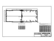
ID that works well. Enlarge the inside diameter slightly with a round file to accommodate thePTT switch and then paint it black.The miniature slide switches used for S1-S4 weren’t my first choice as they are almost too shortto protrude through the thickness of the desk stand. However, right angle printed circuit mountSP3T and DPDT toggle or rotary switches are expensive and somewhat hard to find.Drill and cut all holes on the front and rear of the desk stand. Note that the holes should be cut sothat they are parallel to the bottom of the stand, not perpendicular to the front or rear panels. Iused a Dremel tool to remove the cable clamp inside the desk stand. After the drilling and filingare complete repaint the entire desk stand with flat black spray paint to cover the exposedaluminum. When dry, place the painted stand in the oven for an hour at 250ºF. Labeling can beadded using a label maker with white characters on clear tape. An aluminum bottom plate is cutto fit the bottom of the desk stand and four holes are drilled to match the rubber feet mountingscrews. The PC board is mounted on four 0.3125” long standoffs that are attached to the bottomplate. I used a disc sander to remove 1/16” from the length of 3/8” standoffs. A Shure A2WSmicrophone windscreen completes the setup.Two PC board layouts are provided. The first layout, 2.5” x 5.85”, was used on the prototype forthis project. The second layout is smaller at 2.5” x 3.8” and takes advantage of the MiniBoardservice offered by ExpressPCB 4 for considerable cost savings. Three MiniBoards cost less thantwo Standard Service boards. The smaller layout will fit inside a 4”x4”x2” enclosure with anXLR dynamic microphone input and a 1/8” phone jack for an electret microphone input on thefront. The rear contains round 8-pin Foster and RJ-45 microphone output jacks. Internal jumpersallow the filter to be configured to most radios.ConclusionThe <strong>SSB</strong> <strong>Mic</strong>rophone <strong>Filter</strong> is a great way to get different responses from one microphone toadapt to changing band conditions. It will help to reduce the low frequencies of a bassy voice toimprove intelligibility in noisy band conditions, or boost the high frequencies to work that DXpileup. The circuit can be built into a desk stand or its own enclosure and powered by themicrophone voltage or radio power supply. Comparable to antenna modeling, analog circuitsimulations can be made using TINA-TI. This program is a great learning tool and allows thebuilder to customize the filter response before any solder is melted.Allen Baker, <strong>KG4JJH</strong>kg4jjh@arrl.netwww.kg4jjh.com<strong>SSB</strong> <strong>Mic</strong>rophone <strong>Filter</strong> Page 4 of 5 Allen Baker, <strong>KG4JJH</strong>
Acknowledgements1. Yaesu MD-100A8X Desktop <strong>Mic</strong>rophone, Universal Radio Inc., http://www.universalradio.com/catalog/mics/0287.html2. Audio/Radio Handbook, National Semiconductor Corporation, 1980, p 4-38.3. TINA-TI, SPICE-Based Analog Simulation Program, Texas Instruments, Inc.,http://focus.ti.com/docs/toolsw/folders/print/tina-ti.html4. ExpressPCB, http://expresspcb.com/<strong>SSB</strong> <strong>Mic</strong>rophone <strong>Filter</strong> Page 5 of 5 Allen Baker, <strong>KG4JJH</strong>