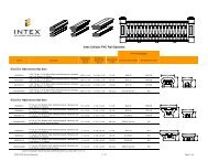
Railing Instructions RS30 Stairs - Intex Millwork Solutions
Railing Instructions RS30 Stairs - Intex Millwork Solutions
Railing Instructions RS30 Stairs - Intex Millwork Solutions

Create successful ePaper yourself
Turn your PDF publications into a flip-book with our unique Google optimized e-Paper software.
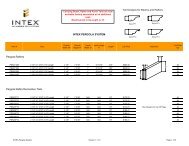
<strong>Intex</strong> <strong>RS30</strong> Stair/Rake Rail Installation <strong>Instructions</strong>Stair or Rake Application1. Determine angle, measure and cut rail sectionsto length.a. Insure newels or columns to whichrail will be mounted are plumb and sturdy enough tosupport rail. If newel/column covers are used, insurethey have blocking at each location where railing will beattached.Baluster Cap Lengthb. Determine and mark anglec. Determine location and cut LowerRail and Baluster Cap to required length.2. Determine baluster layout and assemblerail/baluster section.a. Trim Balusters to desired lengthand angle.Lower Rail Lengthb. For standard baluster spacing (withthe variable spaces at the ends of each rail section) usethe template provided. Align the template referenceedge as indicated to the inside of the bottom rail.Determine best end spacing by either locating abaluster directly at the center of the rail section, or themid-point between two balusters as the center of the rail section, and tape template in center and at ends. Drill a1/8” hole through the template and bottom rail using the appropriate spacing line marked ‘bottom rail’, removetemplate and drill back through each hole at the angle to match balusters. Repeat this for process for the balusterUse this spacing line for the Baluster Capcap, using the same template, but drill through thespacing line marked ‘baluster cap’.Baluster Offset Linec. If equalspacing between all balustersand newels/columns isdesired, disregard section ‘a’above and determine spacingbased upon width and numberof balusters (Note: check localbuilding codes for maximumspacing allowed).d. Secure each baluster with one #8 x 2-1/2” Square Drive T17 18-8SSscrew through the baluster cap, and one through the bottom rail. Insure balusters are straightand aligned and secure with one #8 x 1-1/2” Square Drive T17 18-8SS screw through thebottom rail (offset from center) to preclude baluster from rotating after installation.Upper Stair BracketUse this spacing line for the Bottom RailBottom Rail Bracket GasketTemplate CenterAlign either the Template Center orBaluster Offset Line with the mid-pointof the rail sectionLower Stair BracketTemplateRailAngleTemplate PlacementTemplateBaluster CapTemplateBottom Rail (inverted)3. Prepare aluminum reinforcements.a. Attach a lower stair bracket (90degree bend) using two #8 x 1-1/4” Square Drive T1718-8SS screws supplied to the lower end of eachreinforcement. Note: on the bottom (white) railreinforcement, insert one of the gaskets suppliedbetween the bracket and the aluminum reinforcement.Lubricate the threads with oil or soap to avoid bindingor stripping screws Note: Do not cut this end of thereinforcement to the rail angle.<strong>RS30</strong>STINST 1-1-10
. Measure and cut the upper end of both reinforcements to the rail angle determined in Step 1,include the protruding portion of the lower bracket as part of the total length. Attach an upper stair bracketto the angle cut end of the top (mill finish) rail reinforcement, with the bracket flush with the top of thereinforcement, using four #8 x 1-1/4” Square Drive T17 18-8SSscrews supplied. Attach an upper stair bracket to the angle cut endUpper Stair Bracketof the bottom (white) rail reinforcement, with the bracket flush withthe bottom of the reinforcement, using four #8 x 1-1/4” Square DriveT17 18-8SS screws supplied. Note: on the bottom (white) railreinforcement, insert one of the gaskets supplied between thebracket and the aluminum reinforcement. Lubricate the threads withoil or soap to avoid binding or stripping screws.Top Rail Reinforcement (milled)Bottom Rail Reinforcement (white)c. Cut one end of crush block to angle of rail andlocate to the bottom (white painted) aluminum rail reinforcement, withspacing no greater than 32” from the end, or between crush blocks.Insure that crush block(s) will be located on a stair tread.d. Drill a 3/16” hole through the aluminum railreinforcement, and secure each crush block using one #8 x 2-1/2” Square Drive T17 18-8SS screw.4. Install raila. Position bottom aluminum rail reinforcement, with crush block(s) attached, between newels orcolumns, centered in newel or column face, and secure each end with three #10 x 3” Slot Hex Washer Head TA18-8SS screws supplied.b. Position vinyl rail/baluster assembly between newels or columns and seat fully down onbottom aluminum rail reinforcement.c. Seat remaining aluminum reinforcement into baluster cap.d. Insure rail is centered on face of newel or column and secure each end with three #10 x 3”Slot Hex Washer Head TA 18-8SS screws supplied.e. Drill a 3/16” hole through the aluminum reinforcement over every third baluster (note: offset toavoid the screw which is into the top of each baluster) and secure the aluminum reinforcement to the rail/balusterassembly using #8 x 2-1/2” Square Drive T17 18-8SS screwsf. Measure and cut Top Cap. Drill a 3/16” holedown through the aluminum reinforcement and the baluster cap,plumb, at both ends and near the center of the span (all betweenbalusters). Seat the Rail Cap fully onto Baluster Cap, and use thescrews provided to attach Rail Cap, screwing up through theunderside of the Baluster Cap. Note: screws provided for <strong>RS30</strong>350rail are #8 x 1-7/8” Square Drive T17 18-8SS, and screws for<strong>RS30</strong>400 rail are #8 x 2-1/4” Square Drive T17 18-8SS white heads.SCREWPlease see rail installation instructions included with rail kit for parts list and otherinformation<strong>RS30</strong>STINST 1-1-10