OMNIMOUNT UNIVERSAL MOUNTING SYSTEMS - Canford Audio
OMNIMOUNT UNIVERSAL MOUNTING SYSTEMS - Canford Audio
OMNIMOUNT UNIVERSAL MOUNTING SYSTEMS - Canford Audio

Create successful ePaper yourself
Turn your PDF publications into a flip-book with our unique Google optimized e-Paper software.
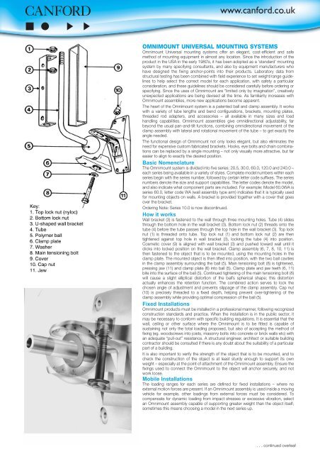
<strong>OMNIMOUNT</strong> <strong>UNIVERSAL</strong> <strong>MOUNTING</strong> <strong>SYSTEMS</strong>Omnimount Universal mounting systems offer an elegant, cost-efficient and safemethod of mounting equipment in almost any location. Since the introduction of theproduct in the USA in the early 1980’s, it has been adopted as a ‘standard’ mountingsystem by many specifying consultants, and also by equipment manufacturers whohave designed the fixing anchor-points into their products. Laboratory data fromstructural testing has been combined with field experience to set weight/range guidelinesto help select the correct model for each application, with safety a particularconsideration, and these guidelines should be considered carefully before ordering orspecifying. Since the uses of Omnimount are “limited only by imagination”, creativelyunexpected applications are being devised all the time. As familiarity increases withOmnimount assemblies, more new applications become apparent.The heart of the Omnimount system is a patented ball and clamp assembly. It workswith a variety of tube lengths and bend configurations, brackets, mounting plates,threaded rod adapters, and accessories – all available in many sizes and loadhandling capabilities. Omnimount assemblies give omnidirectional adjustability, farbeyond the usual pan-and-tilt functions, combining omnidirectional movement of theclamp assembly with lateral and rotational movement of the tube – to get exactly theangle needed.The functional design of Omnimount not only looks elegant, but also eliminates theneed for expensive custom fabricated brackets. Hooks, eye bolts and chain combinationscan be replaced by a single mounting – not only visually more attractive, but fareasier to align to exactly the desired position.Basic NomenclatureThe Omnimount system is divided into five series: 20.5, 30.0, 60.0, 120.0 and 240.0 –each series being available in a variety of styles. Complete model numbers within eachseries begin with the series number, followed by certain letter code suffixes. The seriesnumbers denote the size and support capabilities. The letter codes denote the model,and also indicate what component parts are included. For example: Model 60.0WA isseries 60.0, letter code WA (wall assembly type arm) indicates that it is typically usedfor mounting objects on walls. A bracket is provided together with a cover that goesover the bracket.Ordering Note: Series 10.0 is now discontinued.How it worksWall bracket (3) is fastened to the wall through three mounting holes. Tube (4) slidesthrough the bottom hole in the wall bracket (3). Bottom lock nut (2) threads onto thetube (4) before the tube passes through the top hole in the wall bracket (3). Top locknut (1) is threaded onto tube. Top lock nut (1) and bottom lock nut (2) are thentightened against top hole in wall bracket (3), locking the tube (4) into position.Cosmetic cover (9) is aligned with wall bracket (3) and pushed toward wall until itclicks into locked position on the wall bracket. Clamp assembly (6, 7, 8, 10, 11) isthen fastened to the object that is to be mounted, using the mounting holes in theclamp plate. The mounted object is then lifted into position, with the two ball cavitiesin the clamp assembly surrounding the ball (5). Main tensioning bolt (8) is tightened,pressing jaw (11) and clamp plate (6) into ball (5). Clamp plate and jaw teeth (6, 11)bite into the surface of the ball (5). Continued tightening of the main tensioning bolt (8)will cause a slight elliptical distortion of the ball’s spherical shape; this distortionactually enhances the retention function. The combined action serves to lock thechosen angle of adjustment and prevents slippage of the clamp assembly. Cap nut(10) is precisely threaded to a fixed depth, helping prevent over-tightening of theclamp assembly while providing optimal compression of the ball (5).Fixed InstallationsOmnimount products must be installed in a professional manner, following recognizedconstruction standards and practice. When the installation is in the public sector, itmay be necessary to conform with specific building regulations. It is essential that thewall, ceiling or other surface where the Omnimount is to be fitted is capable ofsustaining not only the total loading proposed, but also of accepting the method offixing (eg. woodscrews into joists, masonry bolts into concrete or brick walls etc) withan adequate “pull-out” resistance. A structural engineer, architect or suitable buildingcontractor should be consulted if there is any doubt about the suitability of a particularpart of a building.It is also important to verify the strength of the object that is to be mounted, and tocheck the construction of the object is at least sturdy enough to support its ownweight – especially at the point of attachment of the Omnimount assembly. Ensure thefixings used to connect the Omnimount to the object will anchor securely, and notwork loose.Mobile InstallationsThe loading ranges for each series are defined for fixed installations – where noexternal motion forces are present. If an Omnimount assembly is used inside a movingvehicle for example, other loadings from external forces must be considered. Tocompensate for dynamic loading from impact stresses or excessive vibration, selectan Omnimount assembly capable of supporting greater weight than the object itself;sometimes this means choosing a model in the next series up.. . . continued overleaf
18-652 <strong>OMNIMOUNT</strong> 20.5 MTA Adapter 20.5 series to M10 threaded rod18-653 <strong>OMNIMOUNT</strong> 30.0 MTA Adapter 30.0 series to M12 threaded rod18-654 <strong>OMNIMOUNT</strong> 60.0 MTA Adapter 60.0 series to M16 threaded rod18-655 <strong>OMNIMOUNT</strong> 120.0 MTA Adapter 120.0 series to M24 threaded rod18-662 <strong>OMNIMOUNT</strong> 20.5 MCP Ceiling plate 20.5 series with M10 nuts18-663 <strong>OMNIMOUNT</strong> 30.0 MCP Ceiling plate 30.0 series with M12 nuts18-664 <strong>OMNIMOUNT</strong> 60.0 MCP Ceiling plate 60.0 series with M16 nuts18-665 <strong>OMNIMOUNT</strong> 120.0 MCP Ceiling plate 120.0 series with M24 nuts14-981 M6 THREADED ROD MS, SC, 1 metre14-982 M10 THREADED ROD MS, SC, 1 metre14-983 M12 THREADED ROD MS, SC, 1 metre14-984 M16 THREADED ROD MS, SC, 1 metre14-985 M24 THREADED ROD MS, SC, 1 metre18-786 <strong>OMNIMOUNT</strong> 20.5 H Quick adjust handle18-780 <strong>OMNIMOUNT</strong> 30.0 H Quick adjust handle (pair)18-787 <strong>OMNIMOUNT</strong> SC-1000 Safety cable18-788 <strong>OMNIMOUNT</strong> 60.0 ISO-W Vibration isolator, wallUK Sales - tel 0191 418 1122 International Sales - tel +44 191 418 1133 Tech Support - tel 0191 418 1144fax 0191 418 1123 fax +44 191 418 1134 fax 0191 418 1145sales@canford.co.uk international@canford.co.uk techsupport@canford.co.uk