SP 4000
SP 4000
SP 4000

You also want an ePaper? Increase the reach of your titles
YUMPU automatically turns print PDFs into web optimized ePapers that Google loves.
<strong>SP</strong> <strong>4000</strong>D811229 11-11-02 Vers. 03AUTOMATIONFOR RACKSLIDING GATES
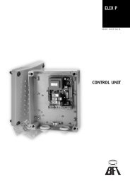
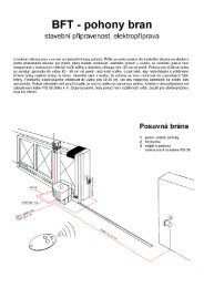
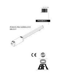
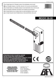
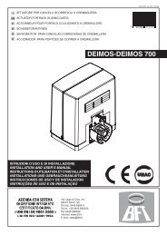
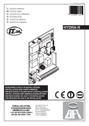
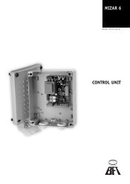
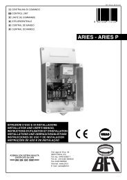
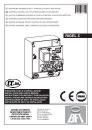
<strong>SP</strong> <strong>4000</strong>110IMPORTANT: In the case where the leaf keeps sliding after the stopcommand, the moulded end section of the runner (fig. 11 ref. “A”) can belengthened so as to stop the runner from going past the end-of-stroke point.WARNING! To avoid inefficiency, or damage to the automation, keep alwaysa space of 4-5cm before the required opening/closing end positions (fig. 12).10) GATE BACKSTOPSDANGER - The gate must be provided with mechanical backstops both onclosing and opening (fig. 12 ref. “F”) in order prevent it from coming out ofthe upper guide.The mechanical stops must be sturdily secured to the ground, a fewcentimetres beyond the electric stop point.11) ELECTRICAL INSTALLATION SET-UPLay out the electrical installation as shown in fig. 13, with reference to theCEI 64-8 and IEC 364 provisions complying with the HD 384 and othernational standards in force for electrical installation.WARNING – Check the actuator rating.For the 400V three-phase version, connect the mains using a multipolar R-S-T-N+EARTH cable having a minimum cross section of 2.5 sq mm andcomplying with the current national standards (e.g.: H07RN-F type).For the 230V three-phase version, connect the mains using a multipolar R-S-T+EARTH cable having a minimum cross section of 2.5 sq mm andcomplying with the current national standards (e.g.: H07RN-F type).Connect the control and safety devices in compliance with the previouslymentioned technical installation standards.The mains power supply connections must be kept totally separatefrom the auxiliary connections.Fig. 13 shows the number of connections and the cross section forapproximate lengths of 100 metres; in case of greater lengths, calculate thecross section for the true automation load:The main automation components are (fig. 13):I Type-approved omnipolar circuit breaker with adequate capacityand at least 3mm contact opening, provided with protectionagainst overloads and short circuits, suitable for cutting outautomation from the mains. If not already installed, place a typeapproveddifferential switch with a 0.03A threshold before theautomation systemQR Control panel and incorporated receiverS Key selectorAL Blinker with tuned antennaM ActuatorE Electric lockP Control buttonsCS Electric edgeCC Edge controlFte, Fre Pair of external photocellsFti, Fri Pair of internal photocellsCF PostsT 1-2-4 channel transmitter.WARNING! Operator without torque limiter: install the actuatorwith appropriate safety systems (eg. device type E item 5.5.1 ofEN12453:2000 standard)12) CONTROL PANEL CONNECTIONSAfter the appropriate electric cables have been passed through the racewaysand fixed to the various automation components in the chosen points, thesemust be connected according to the indications and diagrams shown in therelevant instruction manuals.Connect the phase, neutral (230V three-phase excluded), and earth(compulsory) cables. The protection (earth) wire, having a yellow/greeninsulating sheath, must be connected to the appropriately marked terminalsprovided .The automation device is to be operated after all the safety devices havebeen connected and checked.Fig. 14-15 shows the wiring diagram of the panel fitted to the actuator.Here follows a description of the terminals to be connected to the controlpanel (fig.14-15) including the SIRIO TEL mod. unit (fig. 16).PanelN-R-S-T+ EARTH 400Vac ±10%, 50Hz, three-phase panel power supplyR-S-T+ EARTH 230Vac ±10%, 50Hz, three-phase panel power supplySIRIO TEL control unit terminal board (fig.16)N.B.:The board is supplied with a series of previously bridged terminals.The jumpers refer to the following terminals: 26-29, 26-30, 26-31, 26-35.If these terminals are not used, leave them bridged.16AUTOMATION FOR RACK SLIDING GATESJP1 - THREE-PHASE 400V1-2-3-4 Three-phase power supply+neutral 400V (1N - 2R - 3S - 4T).8-9 230Vac output for blinker 40W max.JP1 - THREE-PHASE 230V2-3-4 Three-phase power supply 230V (2R - 3S - 4T).8-9 230Vac output for blinker 40W max.JP210-11 24Vac (3W) output for gate-open warning light.11-12 24Vac power supply to accessories and safety devices which arenot checked.12-13 24VTx power supply only for safety device transmitters which arechecked.14 LOOP1 input for safety device check ring (see fig.5).15 LOOP2 input for safety device check ring (see fig.5).16-17 Second radio channel output for two-channel receiver board(n.o.).18-19 Antenna input for radio receiver board (18 signal, 19 braid).JP720-21-2223-24-25 Outputs for the connection of safety devices which are to bechecked (see fig.5).JP426-27 START button (n.o.).26-28 Block button (n.c.). Additional buttons to be connected in serieswith one another.26-29 Photocell contact input (n.c.). If not used, leave on. If used whilechecking, observe wiring diagram in fig.5.26-30 Opening limit switch (n.c.). If not used, leave bridged.26-31 Closing limit switch (n.c.). If not used, leave bridged.26-32 Pedestrian access button (n.o.).26-33 Open button (n.o.).26-34 Close button (n.o.).26-35 IR edge contact input (n.c.). If not used, leave bridged.JP6 1-2 channel radio receiver board connector.12.1) Check of directionWARNING! Before supplying the system with power, it is compulsoryto check the “DIRECTION OF ROTATION” as described below.1) Activate the release as described in the paragraph on “EMERGENCYMANOEUVRE”.2) Bring the leaf to the fully closed position by hand (limit microswitchpressed).3) When the system is supplied with power (control unit door and boxopen), the SWC LED must be off.If the LED are on, the SWO and SWO limit switch connections must bereversed in the control unit.4) Bring the leaf to the half-way position by hand.5) Restore motorised operation (“EMERGENCY MANOEUVRE”) andreposition the box door to close the respective safety contact.6) Disconnect the mains power supply temporarily to reset the control unit.7) At the first start command, the control unit always carries out theopening manoeuvre; check the following:a) if the gate moves along the opening direction, the direction ofrotation of the actuator is correct;b) if the gate moves along the closing direction, disconnect the mainspower supply and invert two phases in the control unit power supplyterminal board.8) Connect the mains power supply and carry out a complete checking cycle.13) CONNECTION TO SAFETY DEVICES• In case of standard devices with 4 terminals and without self-diagnosticfunction, the connection can be carried out without verification as indicatedin point 13.1.• In case of devices featuring internal self-diagnostic function, refer to point 13.2.• The standard devices with 5 terminals and without self-diagnostic functioncan be included in the control and self-diagnostic cycle observing theinstructions given in point 13.3.13.1) Safety devices WITHOUT SELF-DIAGNOSISConnections must be carried out as shown in fig. 18. Keep the Dip-switches 9and 10 in the ON position (standard setting). The tripping contacts of a groupof devices of the same type, must be connected in series with one another.13.2) Safety devices WITH INTERNAL SELF-DIAGNOSISConnections must be carried out as shown in fig.18. Keep the Dip-switches 9and 10 in the ON position (standard setting). The tripping contacts of severaldevices of the same type, must be connected in series.D811229_03
<strong>SP</strong> <strong>4000</strong>D811229_0313.3) Safety devices WITHOUT SELF-DIAGNOSIS but with voltage-freeEX-CHANGE CONTACTS.We conventionally make reference to a receiving device (RCS- fig.5) with 5terminals which have the following functions: terminals 1 and 2 are for 24Vacpower supply, terminal 3 is a common terminal, terminal 4 is a normally closedcontact not in use, terminal 5 is a normally open contact not in use.A) Fig. 19 “A” shows the wiring diagram for connecting the power supply tothose receivers and transmitters for which a self-diagnosis is required.B) Fig. 19 “B”. Connection of one or more receivers (photocell) of the sametype up to a maximum of four (Dip 9 OFF/Dip 10 ON, photocells only, leavejumped 35-26). For example, if there are two photocells, connect F1 and F2,then interrupt the connection chain by connecting the terminal 4 of F2 toLOOP1 and the terminal 5 of F2 to COM. If only one receiver has to beconnected, connection must be made as shown in fig.19 ref.1. If thereceivers to be connected are less than four, it is necessary to interrupt theconnection chain by performing the connections as shown in fig.19 ref. 2 or3. If rubber edges instead of photocells have to be connected, use terminal35-BAR of the control unit.If the devices concerned are rubber edges instead of photocells, use terminal35-BAR in the control unit (Dip 9 ON/Dip 10 OFF, leave jumped 29-26).C) Connection of one photocell and one rubber edge.(Dip 9 OFF/Dip 10 OFF)D) Connection of two photocells and one rubber edge.(Dip 9 OFF/Dip 10 OFF)When connecting two rubber edges and one photocell, F1 and F2 in fig.19“D” become 2 rubber edges, and C1 one photocell; invert the connectionsPHOT and BAR of the control unit with one another.(Dip 9 OFF/Dip 10 OFF)E) Connection of three photocells and one rubber edge. When connectingthree rubber edges and one photocell, F1, F2 and F3 (fig.19 “E”) become3 rubber edges and C1 one photocell; invert the connections PHOT andBAR of the control unit with one another.(Dip 9 OFF/Dip 10 OFF)F) Connection of three photocells and two rubber edges When connectingthree rubber edges and two photocells, F1, F2 and F3 (fig.19 “F”) becomethree rubber edges, C1 and C2 two photocells; invert the connectionsPHOT and BAR of the control unit with one another.(Dip 9 OFF/Dip 10 OFF)G) Connection of four photocells and one rubber edge. When connecting fourrubber edges and one photocell, F1, F2 , F3 and F4 (fig.19 “G”) become fourrubber edges and C1 one photocell; invert the connections PHOT and BARof the control unit with one another.(Dip 9 OFF/Dip 10 OFF)14) OPERATION LOGIC14.1) Dip-switchDip 1 and 2 ..................................................................... Photocells (FCH)ON - Excludes photocell operation during gate opening, and immediatelyreverses movement during the closing phase when the photocell is obscured.OFF - In the case where the photocell is obscured by an obstacle during theclosing manoeuvre, the gate is stopped; when the obstacle is removed, thegate reopens. In the case where the photocell is obscured by an obstacle duringthe opening manoeuvre, the gate is stopped; when the obstacle is removed,the gate continues to open.Dip 3 .................................................................... Impulse blocking (IBL)ON - The Start / Start pedestrian impulse has no effect during the openingphase.OFF - The Start / Start pedestrian impulse during the opening phase causesthe gate to stop.Dip 4 ................................................................. Automatic closing (TCA)ON - Automatically closes the gate after a dwell time set by the TCAtrimmer.The automatic closing manoeuvre is activated after the gate hasreached the opening end-of-stroke position, after the gate opening time hasended, or after the gate has stopped in the opening phase due to a Startimpulse.OFF - Excludes automatic closing.Dip 5 2 or 4 step logic (2P/4P)ON - A Start impulse given during the closing phase reverses the direction ofmovement, during the opening phase it stops the gate. (Dip-switch OFF).OFF - A Start impulse given while the gate is moving, causes it to stop; thefollowing impulse reverses the running direction. (4-step logic).N.B.: The Start impulse in the opening phase has no effect when Dip-switch 3is ON.Dip 6 ......................................................................... Pre-alarm (PREALL)ON - The blinker comes on about 3 seconds before the motor starts.OFF - The blinker comes on at the same time as the motor starts.Dip 7 ............................................................Open/Close command (U.P.)Activates the signals connected to terminals 33-34.ON - Hold-to-run operation: the manoeuvre continues as long as pressure ismaintained on the command button.OFF - Separate automatic Open/Close operation: by means of an impulse, itopens the gate if closed and vice versa.Dip 8 ........................... Reduced or normal operation time range (S.TW)ON - TW operation time ranging between 1-90 seconds (TW.PED pedes-trianoperation time from 1 to 20 seconds).OFF - TW operation time ranging between 3÷210 seconds (TW.PED pedestrianoperation time from 5 to 60 seconds).Dip 9 .......................................................... Unchecked photocells (FNV)Activates the photocell control logic.ON - The photocells are excluded from the safety check cycle which is carriedout before each manoeuvre; however their logic state is analysed (for connection,refer to the typical method of connecting photocells with continuously activebeams). This is used to connect photocells which have not been checked orhave internal self-diagnosing systems, and always provide a voltage-freeoutput contact.OFF - The photocells are included in the Ok safety check cycle which is carriedout before each manoeuvre. For connection, refer to the enclosed diagrams.Dip 10 ................................................................. Unchecked edge (BAR)Activates the rubber edge device control logic.ON - The edge devices are excluded from the safety check cycle which iscarried out before each manoeuvre; however their logic state is analysed (forconnection, refer to the typical method of connecting infrared edges withcontinuously active beams). This is used to connect IR edges which have notbeen checked or have internal self-diagnosing system, and always provide avoltage-free output contact.OFF - The IR edge devices are included in the Ok safety check cycle which iscarried out before each manoeuvre. For connection, refer to the encloseddiagrams.14.2) Trimmer-set functionsTW.PED Sets the partial operation time of a sliding gate which is beingused for both vehicles and pedestrians.TW Sets the operation time during both the opening and closingphases (adjustable from 3 to 210 seconds).TCA Sets the dwell time, after which the gate closes automatically(from 1 to 120 seconds).14.3) LED functionsThe SIRIOTEL control unit is provided with leds which are useful in identifyingany anomalies in the system.(DL1) Stays on when supplied with mains power and with F1 fuse intact.(DL2) Comes on when the motor is activated during closing.(DL3) Comes on when the motor is activated during opening.(DL4) Comes on following the Start command or the activation of thefirst radio-receiver channel.(DL5)(DL6)Goes off when the block command is activated.Goes off when photocells are not aligned, i.e. when obstacles arepresent. When Dip-switch 9 is OFF, the photocells and relatedleds are only activated during manoeuvring.(DL7) Goes off when the gate is in the completely open position, ifprovided with end-of-stroke device.(DL8) Goes off when the gate is in the completely closed position, ifprovided with end-of-stroke device.(DL9) Comes on at the Start command for pedestrian gate.(DL10)(DL11)(DL12)(DL13)(DL14)Comes on with manual opening command.Comes on with manual closing command.Goes off when the pneumatic edge is activated. When Dip-switch10 is OFF, the edge and its related LED are only activated duringmanoeuvring.Comes on when the safety ring is closed.Comes on when the safety micro has stepped in.15) EMERGENCY MANOEUVREWhen the electric supply is disconnected or the automation is faulty, the leafmust be opened manually.15.1) Activation• Open the front actuator door using the key provided (fig.23).At the time of opening, a safety microswitch stops the actuator (fig.23- ref. “S”) from operating electrically.• Take out the release key (fig.23 ref. “C”) located inside the box andinsert it in the release screw (fig.24 ref. “V”) .• Turn key “C” anticlockwise until the pinion drive system becomescompletely loose.This way, the pinion is released and the gate can be operated manually.WARNING - Considering the leaf weight, it is recommended to guide theleaf manually along the entire run, and absolutely avoid pushing it in anuncontrolled way.15.2) Re-activation• Open the actuator door with the appropriate key.• Insert the release key in the release screw (fig.24 - ref. “V”) and turn itclockwise until it is completely tightened.• Put the release key back in its place, close the actuator door and checkP<strong>4000</strong> V 03 17111AUTOMATION FOR RACK SLIDING GATES
<strong>SP</strong> <strong>4000</strong>112that the automation operates electrically.• Put the actuator door key away in a safe place known to the operators.16) AUTOMATION TESTINGBefore the installation is made fully operational, carry out the followingchecks.• Check that the overload cutout (fig.22 – ref. “SM”) is set for the ratedcurrent absorbed by the motor (400V / 2.8A) -(230V / 4.84A).• Check that all safety devices (limit microswitches, photocells, electricedges, etc.) operate correctly.• Check the tightening torque of the pinion release (emergency release).• Check that the leaf stops within the time and limits provided for bycurrent prescriptions.• Check that the rack-pinion mesh is correct (4mm minimum play).• Check that the opening and closing end-of-stroke runners are correctlypositioned and secured.• Check the start and stop operation in case of manual control.• Check the start and stop operation in case of remote radio control.• Check the normal or customised function logic.• Check that all components are tightly secured.• Apply the danger warning label (fig. 23).17) CONTROLThe use of this control device allows the gate to be opened and closedautomatically. There are different types of controls (manual, remote,magnetic badge access control, etc.) depending on the installation requirementsand characteristics.For the various control systems, refer to the applicable instructions.Explain the correct operation of the automation device to the endusers.18) MaintenanceWARNING! Any maintenance operation must be carried out by qualifiedpersonnel (see paragraph 2).• Check the play between the pinion and rack (4mm c.a.). Moderatelyclean and grease the rack.• Always keep the sliding track clean and free from debris.• Occasionally clean the photocell optical elements.• Check the correct tightening torque of the pinion release screw.• When any operational malfunction is found, and not solved, disconnectthe mains power supply. When automation is out of order, activate theemergency release (see paragraph “EMERGENCY RELEASE”) so asto put the pinion in neutral and allow the gate to be opened or closedmanually.19) NOISEThe aerial noise produced by the gearmotor under normal operatingconditions is constant and does not exceed 70dB(A).20) SCRAPPINGMaterials must be disposed of in conformity with the current regulations.In case of scrapping, the automation devices do not entail any particularrisks or danger.In case of materials to be recovered, these should be sorted out by type(electrical components, copper, aluminium, plastic etc.).21) DISMANTLINGWhen the automation system is disassembled to be reassembled onanother site, proceed as follows:• Disconnect the power supply and the entire electrical installation.• Remove the gearmotor from its fixing base.• Disassemble the control panel, if separate, and all installation components.• In the case where some of the components cannot be removed or aredamaged, they must be replaced.cause of any fault. If the LEDs show a persistent unwanted startcommand, check that there are no radio controls, start buttons or othercontrol devices keeping the start contact activated (closed).7) If the control units does not work, replace it.22.2) The gate does not open. The motor turns but there is nomovement.1) The manual release was left activated. Restore motorised operation.2) Check whether the gate is well housed in the mechanical end-of-strokestops.Release the gate manually, move it from its position and restoremotorised operation. Check and correct the position of the end-ofstrokerunners to anticipate microswitch intervention. If after electricstoppage there is excessive leaf sliding, check the electric brake airgap, as specified in the motor instruction manual supplied with theproduct.3) Check that the gate does not show mechanical defects, as for examplewheels blocked, pinion/rack misaligned, etc.4) If the motor turns, but the leaf is not strong enough to move, check thatthere are no oil leaks in the coupling, and check the oil level in thehydrodynamic coupling, as explained in the instruction manual for thecoupling.5) Any abundant oil leak may indicate that the hydrodynamic couplingthermal protection has been triggered. Find the hidrodynamic couplingoil plug, the appropriate type of oil and proceed as follows:Disconnect the mains power supply.Remove the box.Remove the actuator from its fixing base and lay it down tilted to theright with the motor in a horizontal position.Rotate the hydrodynamic coupling by hand until it shows the greenthermal plug (fig.24 ref. TV) to be replaced.For maintenance and repair, carefully read the hydrodynamic couplinginstruction manual supplied with the product, and follow the relevantinstructions.Reposition the actuator in the base plate, align and secure it.Refit the box, the doors and then recheck operation.The descriptions and illustrations contained in the present manualare not binding. The Company reserves the right to make any alterationsdeemed appropriate for the technical, manufacturing and commercialimprovement of the product, while leaving the essential productfeatures unchanged, at any time and without undertaking to updatethe present publication.22) MALFUNCTION: CAUSES AND REMEDIES.22.1) The gate does not open. The motor does not turn.1) Check that the system is supplied with power (see main switch).2) Check that the door safety microswitch operates correctly.3) Check that the overload cutout located inside the control panel has notbeen activated; if necessary, restore operation using the appropriatebutton and check current absorption by means of amperometric pliers.4) Check that the photocells or electric edges are neither dirty norengaged nor misaligned. Otherwise proceed accordingly.5) Check that the electronic equipment is correctly supplied with power.Check that the fuses are not damaged.6) By means of the control unit diagnosing LEDs (see respectiveinstructions), check that the functions are correct. If not, identify theD811229_03AUTOMATION FOR RACK SLIDING GATES
<strong>SP</strong> <strong>4000</strong>Fig. 12min. 50mmmin. 50mm≥20mmFFig. 13115CCCSCMQr CFFtiFreCCCSFteAlS3x1mm 2PT2x1mm 2 4x1mm 2FriCF2x1mm 23x1mm 2I*4x1mm 2 RG58D811229_03**400V 3~ 5x2.5mm 2230V 3~ 4x2.5mm22x1.5mm 2*AUTOMATION FOR RACK SLIDING GATES
<strong>SP</strong> <strong>4000</strong>*Fig.15K3 A1 K2 A1 K1A1A2A2K0K0+ ~ ~ -M3~230V3*2*1*4*5*11741 40 39 38 374243444546474849SIRIOTEL2305051N R S T525326 27 28 29 30 31 32 33 34 35 3620 21 22 23 24 2510 11 12 13 14 15 16 17 18 19R S T230V ~*7 x 1,5 mm2D811229_03AUTOMATION FOR RACK SLIDING GATES
<strong>SP</strong> <strong>4000</strong>Fig. 1641 40 39 38 37230V S 400V SafetyJP5RV1T1C4IC1F1C7+R84243444546470.2ATU3U22ATC3+R1F2+C2DL2C1R64849K9U1R31TWPEDR32R33C11ON1 2 3 4 5 6 7 8 9 10U4- + - TCA + - TW +Y1+C37U5C8U10DIP function1 FCH2 FCH3 IBL4 TCA5 2P/4P6 PREALL7 U.P.8 S.TW9 FNV10 BARR10450R105D20 D19D14 D15 D13 D18 D26D16 D17R5K8U8U6 U7DL2 DL3 DL4 DL5 DL6 DL7 DL8 DL9 DL10 DL11 DL12 DL1351 52K7R753F3F2ASIRIOTELK426 27 28 29 30 31 32 33 34 35 36COM START STOP PHOT SWO SWC PED OPEN CLOSE BAR MICRODL14JP7NAR NCB CFB NAA NCA CFA20 21 22 23 24 25K10JP6RICEVNL118JP1N R S T BLINK1 2 3 4 5 6 7 8 9JP210 11 12 13 14 15 16 17 18 19SCA 24VAC TX L1 L2 IICAN ANT SHLDFig. 17 Fig. 1824VAC11121326COM29PHOTSIRIOTEL35BARJP426 27 28 29 30 31 32 33 34 35 36Dip 9Dip 10ONONCOMSTARTSTOPPHOTSWOSWCPEDAPRECHIUDEBAR1 2 3 4 51 2 3 4 5NONCNCNCD811229_03NONONONCRx FLRx RITx FL1 2 1 2Tx RIS1JP1 SIRIO TEL 2302 3 4 8 9JP210 11 12 13 14 15 16 17 18 19R S T230V ~230V40WJP1 SIRIO TEL 40024V3W24Vac24V TxLOOP1LOOP2CH2ANT.12 3 4 8 9JP720 21 22 23 24 25N R S T400V ~230V40Wfig.19AUTOMATION FOR RACK SLIDING GATES
<strong>SP</strong> <strong>4000</strong>A1124Vac12SIRIO TEL1224VTx13RXTX1234512B2214-LOOP126-COM252120Fig. 19SIRIO TEL242326-COM29-PHOT35-BARF4F3F2F11 2 3 4 5 1 2 3 4 5 1 2 3 4 5 1 2 3 4 54-14 LOOP1 / 5-26 COM 4-14 LOOP1 / 5-26 COM 3-26 COM / 4-14 LOOP13 2 1C15-LOOP22435-BARSIRIO TEL26-COM29-PHOTC1F11 2 3 4 5 1 2 3 4 5D15-LOOP235-BARSIRIO TEL242326-COM29-PHOTE15-LOOP235-BAR119D811229_032526-COMSIRIO TEL2426-COM26-COM29-PHOTFGC3F21 2 3 4 5 1 2 3 4 515-LOOP22120C11 2 3 4 515-LOOP235-BARC11 2 3 4 52226-COMC21 2 3 4 52226-COMF41 2 3 4 5F11 2 3 4 52526-COMSIRIO TEL2423F3F21 2 3 4 5 1 2 3 4 5252120SIRIO TEL2423F3F21 2 3 4 5 1 2 3 4 5C11 2 3 4 526-COM29-PHOTF11 2 3 4 526-COM29-PHOTF11 2 3 4 5F3F21 2 3 4 5 1 2 3 4 5F11 2 3 4 5LegendaRX: ricevente fotocellule o coste infrarossi.TX: trasmittente fotocellule o coste infrarossi.F1 - F2 - F3 - F4: dispositivi riceventi fotocellule.C1 - C2 - C3 - C4: dispositivi riceventi coste sensibili.KeyRX: photocell receiver or infrared rubber edges.TX: photocell transmitter or infrared rubber edges.F1 - F2 - F3 - F4: photocell receiving devices.C1 - C2 - C3 - C4: rubber edge receiving devices.LégendeRX: récepteur cellules photoélectriques ou barres palpeuses à infrarouges.TX: émetteur cellules photoélectriques ou barres palpeuses à infrarouges.F1 - F2 - F3 - F4: dispositifs récepteurs cellules photoélectriques.C1 - C2 - C3 - C4: dispositifs récepteurs barres palpeuses.ZeichenerklärungRX: Empfangsteil der Photozellen oder Infrarotleisten.TX: Sendeeinheit der Phototellen oder Infrarotleisten.F1 - F2 - F3 - F4: Empfangsvorrichtungen der Photozellen.C1 - C2 - C3 - C4: Empfangsvorrichtungen der Sicherheitsleisten.LeyendaRX: receptor fotocélulas o barras de infrarrojos.TX: receptor fotocélulas o barras de infrarrojos.F1 - F2 - F3 - F4: dispositivos receptores fotocélulas.C1 - C2 - C3 - C4: dispositivos receptores barras sensibles.LegendaRX: ricevente fotocellule o coste infrarossi.TX: trasmittente fotocellule o coste infrarossiF1 - F2 - F3 - F4: dispositivi riceventi fotocellule.C1 - C2 - C3 - C4: dispositivi riceventi coste sensibili.Fig. 20Fig. 21SCCVAUTOMATION FOR RACK SLIDING GATES
<strong>SP</strong> <strong>4000</strong>2.26,35,2Fig. 22400V 3~2.73.2230V 3~4120Fig. 23Fig. 24TVD811229_03AUTOMATION FOR RACK SLIDING GATES