

AD05-P, AD10-P data sheet - Trend
AD05-P, AD10-P data sheet - Trend
AD05-P, AD10-P data sheet - Trend

Create successful ePaper yourself
Turn your PDF publications into a flip-book with our unique Google optimized e-Paper software.
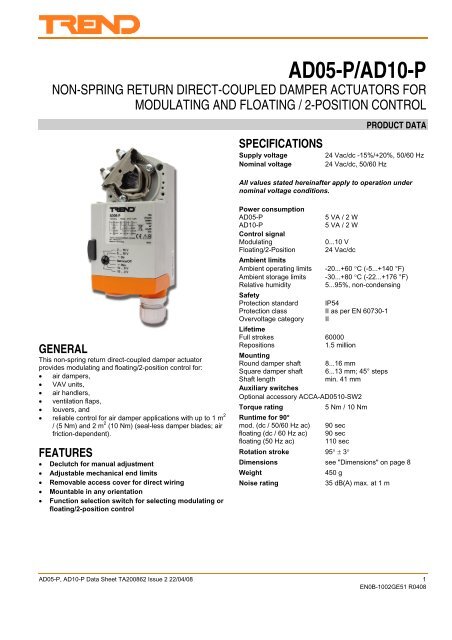
<strong>AD05</strong>-P/<strong>AD10</strong>-PNON-SPRING RETURN DIRECT-COUPLED DAMPER ACTUATORS FORMODULATING AND FLOATING / 2-POSITION CONTROLSPECIFICATIONSSupply voltageNominal voltagePRODUCT DATA24 Vac/dc -15%/+20%, 50/60 Hz24 Vac/dc, 50/60 HzAll values stated hereinafter apply to operation undernominal voltage conditions.GENERALThis non-spring return direct-coupled damper actuatorprovides modulating and floating/2-position control for:• air dampers,• VAV units,• air handlers,• ventilation flaps,• louvers, and• reliable control for air damper applications with up to 1 m 2/ (5 Nm) and 2 m 2 (10 Nm) (seal-less damper blades; airfriction-dependent).FEATURES• Declutch for manual adjustment• Adjustable mechanical end limits• Removable access cover for direct wiring• Mountable in any orientation• Function selection switch for selecting modulating orfloating/2-position controlPower consumption<strong>AD05</strong>-P5 VA / 2 W<strong>AD10</strong>-P5 VA / 2 WControl signalModulating0...10 VFloating/2-Position 24 Vac/dcAmbient limitsAmbient operating limits -20...+60 °C (-5...+140 °F)Ambient storage limits -30...+80 °C (-22...+176 °F)Relative humidity5...95%, non-condensingSafetyProtection standard IP54Protection class II as per EN 60730-1Overvoltage category IILifetimeFull strokes 60000Repositions1.5 millionMountingRound damper shaft 8...16 mmSquare damper shaft 6...13 mm; 45° stepsShaft lengthmin. 41 mmAuxiliary switchesOptional accessory ACCA-<strong>AD05</strong>10-SW2Torque rating5 Nm / 10 NmRuntime for 90°mod. (dc / 50/60 Hz ac) 90 secfloating (dc / 60 Hz ac) 90 secfloating (50 Hz ac) 110 secRotation stroke 95° ± 3°Dimensions see "Dimensions" on page 8Weight450 gNoise rating35 dB(A) max. at 1 m<strong>AD05</strong>-P, <strong>AD10</strong>-P Data Sheet TA200862 Issue 2 22/04/08 1EN0B-1002GE51 R0408
<strong>AD05</strong>-P, <strong>AD10</strong>-PData SheetPRODUCT IDENTIFICATION SYSTEMFig. 1. Product Identification SystemMODELSorder no. supply voltage end switches torque<strong>AD05</strong>-P -- 5 Nm24 Vac/dc<strong>AD10</strong>-P-- 10 NmBASIC FEATURES123456Fig. 2. Setting units and control elementsLegend for Fig. 2:1) Universal shaft adapter2) Mechanical end limits3) Declutch button4) Function selection switch5) Removable access cover6) Anti-rotation bracket7) M20 cable gland7Contents of PackageThe delivery package includes the actuator, parts 1 through 7(see Fig. 2).RUN MODESThe function selection switch (see Fig. 3) can be used toplace the actuator into any one of three different modes:• Service/Off;• the floating/2-position run mode ("Dir" for CCW-closingdampers or "Rev" for CW-closing dampers); and• the modulating run mode.modulating floating/2-position Service/Off2...10 V0...10 VDirService/OffRev10...0 V10...2 V2...10 V 2...10 V0...10 V 0...10 VDirDirService/OffService/OffRevRev10...0 V10...0 V10...2 V10...2 VFig. 3. Function selection switchPower-Off BehaviorIf power is removed, the shaft adapter remains in position.Service/OffIf the function selection switch is set to the "Service/Off"position, then all rotary movement is cancelled, and all controlsignals are ignored, thus allowing the actuator to be manuallyoperated safely.Floating/2-Position Run ModeWithout Feedback SignalIf, however, the function selection switch has been set to oneof the two floating/2-position control settings – but theactuator has not been wired for a feedback signal (see Fig. 11and Fig. 12) – then as soon as operating power is applied, theshaft adapter will run according to the control signals applied.With Feedback SignalIf the function selection switch has been set to one of the twofloating/2-position control settings – and if the actuator hasbeen wired for a feedback signal (see Fig. 11 and Fig. 12) –then as soon as operating power is applied, the shaft adapterwill likewise run first completely counterclockwise and thencompletely clockwise (see also section "Adaption"), afterwhich it will run according to the control signals applied.Modulating Run ModeIf the function selection switch has been set to one of the fourmodulating control settings – and if the actuator is wiredcorrespondingly (see Fig. 10) – then as soon as operatingpower is applied, the shaft adapter will run first completelycounterclockwise and then completely clockwise (see alsosection "Adaption"), after which it will run according to thecontrol signals applied.2 <strong>AD05</strong>-P, <strong>AD10</strong>-P Data Sheet TA200862 Issue 2 22/04/08EN0B-1002GE51 R0408
Data Sheet<strong>AD05</strong>-P, <strong>AD10</strong>-PTable 1 describes, for the floating mode, the shaft adapterbehavior ("stops," rotates "CCW," or rotates "CW") independence upon the control signals applied to terminals 3and 4 and upon the function selection switch setting.Table 2 describes, for the 2-position mode, the shaft adapterbehavior ("stops," rotates "CCW," or rotates "CW") independence upon the control signals applied to terminals 3and 4 and upon the function selection switch setting.Table 3 describes, for the modulating mode, the shaft adapterbehavior ("stops," rotates "totally CCW," rotates "totally CW,"runs to "proportional" position, or runs to "50%" of max.stroke) in dependence upon the control signals applied toterminals 3 and 4 and upon the function selection switchsetting.Table 1. Shaft adapter behavior in the floating modecontrol signal atswitch settingsterminal 3 terminal 4 0[2]...10 V Dir Service / Off Rev 10...0[2] Vopen open -- stops stops stops --open 24 Vac/dc -- CCW stops CW --24 Vac open -- CW stops CCW --Table 2. Shaft adapter behavior in the 2-position modecontrol signal atswitch settingsterminal 3 terminal 4 0[2]...10 V Dir Service / Off Rev 10...0[2] V24 Vac open -- CW stops CCW --24 Vac 24 Vac/dc -- CCW stops CW --Table 3. Shaft adapter behavior in the modulating modecontrol signal atswitch settingsterminal 3 terminal 4 0[2]...10 V Dir Service / Off Rev 10...0[2] Vopenopen totally CCW -- stop -- totally CCW24 Vac/dc 50% -- stop -- 50%< min. control signal plus 0.24 Vopen totally CCW -- stop -- totally CW24 Vac/dc 50% -- stop -- 50%between min. control signal plus 0.24 V open proportional -- stop -- proportionaland max. control signal minus 0.24 V 24 Vac/dc 50% -- stop -- 50%> max. control signal minus 0.24 Vopen totally CW -- stop -- totally CCW24 Vac/dc 50% -- stop -- 50%final position of shaft adapter (% of max. stroke)1005000 0.24upper dead band (9.76 to 10.0 V)range of proportionalactuator movement(0.24 to 9.76 V)lower dead band (0 to 0.24 V)5.0 9.76 10.0control signal (V)current position of shaft adapter (% of max. stroke)10050005 10feedback signal (V)Fig. 4. Final shaft adapter position in dependence uponcontrol signal (example function selection switch settingof 0...10 V)Fig. 5. Feedback signal in dependence upon currentposition of shaft adapter (example function selectionswitch setting of 0...10 V)<strong>AD05</strong>-P, <strong>AD10</strong>-P Data Sheet TA200862 Issue 2 22/04/08 3EN0B-1002GE51 R0408
<strong>AD05</strong>-P, <strong>AD10</strong>-PData SheetAdaptionAdaption is a function in which the actuator re-maps its feedbacksignal and control signal in accordance with repositionedmechanical end limits (see also Fig. 6) and thus recognizestheir new positions.100(before)100(after)final position ofactuator (% of max.)0(after)0(before)0after adaptionbefore adaptionnew position of UPPERmechanical end limitnew position of LOWERmechanical end limitcontrol signal (volts)0final position of actuator (degrees)10.0Fig. 6. Adaption (function selection switch set to"0...10 V")Adaption will be carried out whenever the actuator is in themodulating mode or the floating plus feedback mode or the 2-position plus feedback mode and• the user powers up (from a totally powerless condition) theactuator; or• the user sets the function selection switch to the"Service/Off" setting for at least 2 seconds and then backto its previous setting; or• the control signal's value rises up into the upper deadband (i.e. to more than the max. control signal minus0.24 V) or drops down into the lower dead band (i.e. toless than the min. control signal plus 0.24 V), after whichthe shaft adapter must then remain at the respective(upper or lower) mechanical end limit for at least 3seconds. However, in this case, the actuator will thenrecognize the position of only the respective (upper orlower) mechanical end limit.AccuracyTo achieve very exact positioning or synchronicity fromseveral actuators running in parallel, ensure that the actuatordoes one synchronisation run per day (i.e. drive the actuatorinto the upper dead band, hold for min. 3 sec, then drive theactuator into the lower dead band, and then hold for min. 3sec.) See section "Adaption" for exact voltage levels.OverridingAn override is a condition in which a 24 V signal is applied toterminal 4 of an actuator in the modulating mode, thuscausing the actuator to ignore the control signal at terminal 3,whereupon it will instead move to a position of 50% of itsmaximum stroke (see Table 3).95FeedbackIf correspondingly wired (see Fig. 10, Fig. 11, and Fig. 12),the actuator provides, via terminal 5, a feedback signal proportionalto the actual position of the shaft adapter.MANUAL ADJUSTMENTIMPORTANTTo prevent equipment damage, you must removepower or set the function selection switch to the"Service/Off" position before manual adjustment.After removing power or setting the function selection switchto the "Service/Off" position, the gear train can be disengagedusing the declutch button, permitting the shaft adapter to bemanually rotated to any position. If you have wired theactuator for feedback signal, then, after adaption, thefeedback signal will follow the new position.Limitation of Rotation StrokeTwo adjustable mechanical end limits are provided to limit theangle of rotation as desired (see Fig. 7). The mechanical endlimits must be securely fastened in place.Fig. 7. Mechanical end limitsTo ensure tight closing of the dampers, the shaft adapter hasa total rotation stroke of 95°.After adjusting the mechanical end limits, the user shouldtrigger adaption (see section "Adaption").END SWITCHESNOTE: End switch functionality is provided by optionalaccessory ACCA-<strong>AD05</strong>10-SW2.ACCA-<strong>AD05</strong>10-SW2 provides auxiliary switches which arefreely adjustable between 0 and 90 °4 <strong>AD05</strong>-P, <strong>AD10</strong>-P Data Sheet TA200862 Issue 2 22/04/08EN0B-1002GE51 R0408
<strong>AD05</strong>-P, <strong>AD10</strong>-PData SheetWiring DiagramsModulating: 0[2]...10V, 10...0[2]V24V~/=!0[2]...10V0[2]...10V12345= override optionFig. 10. <strong>AD05</strong>-P/<strong>AD10</strong>-P (modulating mode)AUXILIARY SWITCHESMaximum rating230 Vac5 A resistive3 A inductiveS1 S2 S3BAuxiliary SwitchesAABD110/230 Vac5 (3) AS6 S5 S4AUXILIARY SWITCHESAUXILIARY SWITCHESFig. 13.Auxiliary switches (ACCA-<strong>AD05</strong>10-SW2)CCDS1S2S3S4S5S6Floating: Dir24V~/=124V~/+234CWCCW!0[2]...10V5POS out= feedback optionFig. 11. <strong>AD05</strong>-P/<strong>AD10</strong>-P (floating mode)2-Position: Dir24V~/=124V~/+23424V~/+GND/-Y inPOS 50%POS outGND/-GND/-CWCCW!0[2]...10V5POS out= feedback optionFig. 12. <strong>AD05</strong>-P/<strong>AD10</strong>-P (2-position mode)6 <strong>AD05</strong>-P, <strong>AD10</strong>-P Data Sheet TA200862 Issue 2 22/04/08EN0B-1002GE51 R0408
Data Sheet<strong>AD05</strong>-P, <strong>AD10</strong>-PTable 4 summarizes the information presented in thepreceding wiring diagrams.Table 4. Signals at terminalsterminalmodemodulating floating 2-position1unused or unused or24 V ~/+(with feedback) (with feedback)(power)24 V ~/+ (power) 24 V ~/+ (power)2 common ~/- common ~/- common ~/-30[2]...10 V 24 V ~/+ 24 V ~/+45(control)24 V ~/+(override)0[2]...10 V(feedback)(control signal)24 V ~/+(control signal)unused or(with feedback)0...10 V(control signal)24 V ~/+(control signal)unused or(with feedback)0...10 VNOTE: All cables connected to these terminals must beequipped with spark suppression.<strong>AD05</strong>-P, <strong>AD10</strong>-P Data Sheet TA200862 Issue 2 22/04/08 7EN0B-1002GE51 R0408
<strong>AD05</strong>-P, <strong>AD10</strong>-PData SheetDIMENSIONS41<strong>AD05</strong>-P166108856266Fig. 14. Dimensions (in mm)DISPOSALWEEE Directive:At the end of their useful life the packagingand product should be disposed of by a suitablerecycling centre.Do not dispose of with normal household waste.Do not burn.Please send any comments about this or any other <strong>Trend</strong> technical publication to techpubs@trendcontrols.com© 2008 Honeywell Technologies Sàrl, ECC Division. All rights reserved. Manufactured for and on behalf of the Environmental and Combustion Controls Division ofHoneywell Technologies Sàrl, Ecublens, Route du Bois 37,Switzerland by its Authorized Representative.<strong>Trend</strong> Control Systems Ltd reserves the right to revise this publication from time to time and make changes to the content hereof without obligation tonotify any person of such revisions or changes.<strong>Trend</strong> Control Systems LimitedP.O. Box 34 Horsham, West Sussex, RH12 2YF, UK. Tel: +44 (0)1403 211888, Fax: +44 (0)1403 241608, www.trend-controls.com8 <strong>AD05</strong>-P, <strong>AD10</strong>-P Data Sheet TA200862 Issue 2 22/04/08EN0B-1002GE51 R0408


