L377 - VAQ/RAQ - First Co.
L377 - VAQ/RAQ - First Co.
L377 - VAQ/RAQ - First Co.

Create successful ePaper yourself
Turn your PDF publications into a flip-book with our unique Google optimized e-Paper software.
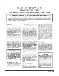
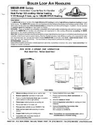
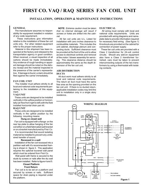
FIRST CO. <strong>VAQ</strong> / <strong>RAQ</strong> SERIES FAN COIL UNITINSTALLATION, OPERATION & MAINTENANCE INSTRUCTIONSGENERALThe manufacturer assumes no responsibilityfor equipment installed in violationof any code requirement.These instructions give informationrelative to the installation of these fan coilunits only. For other related equipmentrefer to the proper instructions.Material in this shipment has been inspectedat the factory and released to thetransportation agency in good condition.When received, a visual inspection of allcartons should be made immediately.Any evidence of rough handling or apparentdamage should be noted on the deliveryreceipt and the material inspected inthe presence of the carrier's representative.If damage is found, a claim should befiled against the carrier immediately.FAN COIL UNITThe installer must adhere strictly to alllocal and national code requirements pertainingto the installation of this equipment.<strong>VAQ</strong> UNITThese units are designed to be installedvertically in the upflow position or horizontally(air flow from right to left) with the fieldinstalled horizontal drain pan kit.<strong>RAQ</strong> UNITThese units are designed to be installedvertically in the upflow position by thefollowing mounting means:Hung on closet wallFan coil is equipped with a flange on therear top plate to allow hanging of the fancoil either on a field fabricated wall bracketor on a bracket manufactured by <strong>First</strong> <strong>Co</strong>.It is recommended that sound isolatingmaterial be installed to prevent any undesiredtransfer of sound.Recessed in a wallInstallation of the fan coil recessed into apartition wall with it's recommended framingis shown in figure 3. This applicationrequires the optional louvered wall panelwhich must be ordered from <strong>First</strong> <strong>Co</strong>.Wall panel with frame is secured to thestuds by screws or nails after the dry wallhas been installed. Refer to figure 4 and 5.Closet PlatformFront ReturnFan coil is to be set on a platform andsecured by screws or nails. Sufficientspace for drain piping is required underthe platform.NOTE: Extreme caution must be takenthat no internal damage will result ifscrews or holes are drilled into the cabinet.All fan coil units are U.L. Listed forinstallation with zero inches clearance tocombustible materials. This includes theunit cabinet, discharge plenum and connectingducts. Sufficient clearance mustbe provided at the front of the unit to allowaccess to electrical controls and removalof the motor / blower assembly for servicing.This clearance distance should beapproximately the same as the depth dimensionof the fan coil unit.AIR DISTRIBUTIONDUCTSAll duct work must adhere strictly to alllocal and national code requirements.The return air duct must have the samefree area as the opening provided on thefan coil unit. If there is no ducted return,applicable installation codes may limit theunit to installation only in a single storyresidence.WHTCAPACITORIF REQ'D.PUMPBLKM1BLKPUMPRELAYBLKBLKWHTFANMOTORBLKWIRING DIAGRAM120VBLKWHTBLKCAP OFFRED LEAD4BLUTRANSF.YEL2FANRELAY21 3WHTRED24VGNDBRNBRNREDBLKDOORSWITCH(OPTIONAL)ELECTRICALAll wiring must comply with local andnational code requirements. Units areprovided with wiring diagrams and nameplatedata to provide information requiredfor necessary field wiring. (See figure 1)Knockouts are provided on the cabinet forconnection of power supply.These fan coil units are provided with aClass 2 transformer for 24-volt controlcircuits. Should any add-on equipmentalso have a Class 2 transformer furnished,care must be taken to preventinterconnecting outputs of the two transformersby using a thermostat with isolatingcontacts.YELBLUREDBRNNH24 VOLTCLASS 2 WIRINGWGRCCOOLING UNITRELAYY120V-1PH-60HZSUPPLYFIELD WIRINGFACTORY WIRINGWGR24V REMOTETHERMOSTATFigure 1
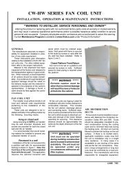
140 degrees as possible with the systemenergized and operating long enough forall temperatures to stabilize.AIR FILTERThe air filter should be cleaned or replacedas often as necessary to preventrestriction of air flow. Always replace thefilter with the same type as originallyfurnished.BLOWER MOTORThe blower motor should be cleanedand oiled with a good grade of SAE 20 oilannually. Normally a few drops of oil ineach bearing is sufficient.PUMP REPLACEMENTDisconnect electrical power beforeservicing the unit.To replace the circulator pump, closethe isolation valves and relieve the waterpressure within the heating loop. Disconnectthe pump's 115 volt power lineswithin the control box and remove the fourhex head screws securing the pumpmotor to the pump's volute.Reverse the above steps for reassemblingthe pump, however make sure thatthe pump or volute has the rubber o-ringin place before assembling.<strong>RAQ</strong> RECESSED WALL MOUNTINGVERTICAL2 x 4WALL STUDSTOP CROSS MEMBER(1" x 2")FLANGE FOR HANGINGIN A CLOSETATTACH UNIT TOFRAME USING6 SCREWS. HOLESIN CABINET ATLOCATIONS SHOWN.UNIT FLUSHWITH WALL STUDS(NOT CRITICAL)BOTTOMCROSS MEMBERLEAVE SUFFICIENT SPACEFOR DRAIN PIPING10" TO 12" MINIMUMRECOMMENDEDSUPPORT FRAMINGFigure 3LIQUIDLINE2 x 4WALL STUDSUCTIONLINEDRY WALLCROSS MEMBER(ON EDGE)<strong>RAQ</strong> WALLPANEL FRAME(PANEL ASSEMBLY ISORDERED SEPARATELY)DRY WALL2 x 4WALL STUDSCREWWALL PANELFRAMEDETAIL OF WALLINSTALLED UNITPANEL FRAMETOP VIEWINSTALLATIONFigure 4 Figure 5
TROUBLESHOOTING(Most likely problems and cause)Important: For system to operate properlypower should be turned ON and allshut - off valves should be OPEN.Pump does not run:These pumps may sometimes “stick”due to non - use and fail to start. Beforereplacing pump:1. Turn off power. Remove large screwplug in end of pump motor and turnshaft several times with a small screwdriver.Replace plug and start system.Pump should start.2. If pump has to be replaced, first shutoff all isolation valves between thewater heater and air handler and relievethe city water pressure by openingthe air purge valve. Then removethe four "allen" head screws that attachthe pump motor to the pumpvolute rather than un-soldering theentire pump assembly.Pump is noisy:Air may still be in the heating loop. Repurgethe system as described under“start - up procedure".Water heater T & P valve “weeping”:This situation usually occurs in thosesystems located in areas where localcodes require the installation of a“backflow preventer” in the cold watersupply line to the water heater. Thissituation is caused by the expansion ofthe water when heated. An expansiontank may be required to solve this problem.<strong>Co</strong>ntact local plumbing authoritiesfor assistance.Hot water circulates through hot watercoil during cooling cycle:Check valve may be stuck open allowing"thermosyphoning" (circulation) of hotwater.Insufficient or no heat:1. Air still in heating loop. Re-purgesystem.2. Inlet and outlet piping connections atthe air handler may be pipedbackwards.(See "Hot water piping".)3. Water heater thermostat not turnedup high enough.4. Water heater thermostat not calibratedproperly.5. Restricted or improperly installed diptube in water heater.6. Restriction somewhere in heatingloop. <strong>Co</strong>nfirm that no other checkvalves or devices have been installedin the heating loop except as suppliedby <strong>First</strong> <strong>Co</strong>.Note: Some water heaters come withtwo factory installed check valves locatedon the space heating connections.Since the circulating pump inthe Aqua Therm ® system may not beable to open these valves in additionto the Aqua Therm ® check valve,these two valves should be removedbefore installation.7. Air handler or hot water coil not largeenough.8. Water heater not large enough.<strong>L377</strong> 8/97