TMS320C5535 eZdsp Reference Technical - Spectrum Digital Support
TMS320C5535 eZdsp Reference Technical - Spectrum Digital Support
TMS320C5535 eZdsp Reference Technical - Spectrum Digital Support

You also want an ePaper? Increase the reach of your titles
YUMPU automatically turns print PDFs into web optimized ePapers that Google loves.
<strong>TMS320C5535</strong> <strong>eZdsp</strong> TM<strong>Technical</strong><strong>Reference</strong>2011 DSP Development Systems
<strong>TMS320C5535</strong> <strong>eZdsp</strong> TM<strong>Technical</strong> <strong>Reference</strong>514585-0001 Rev. AAugust 2011SPECTRUM DIGITAL, INC.12502 Exchange Drive, Suite 440 Stafford, TX. 77477Tel: 281.494.4505 Fax: 281.494.5310sales@spectrumdigital.com www.spectrumdigital.com
IMPORTANT NOTICE<strong>Spectrum</strong> <strong>Digital</strong>, Inc. reserves the right to make changes to its products or to discontinue anyproduct or service without notice. Customers are advised to obtain the latest version of relevantinformation to verify that the data being relied on is current before placing orders.<strong>Spectrum</strong> <strong>Digital</strong>, Inc. warrants performance of its products and related software to currentspecifications in accordance with <strong>Spectrum</strong> <strong>Digital</strong>’s standard warranty. Testing and other qualitycontrol techniques are utilized to the extent deemed necessary to support this warranty.Please be aware that the products described herein are not intended for use in life-supportappliances, devices, or systems. <strong>Spectrum</strong> <strong>Digital</strong> does not warrant nor is <strong>Spectrum</strong> <strong>Digital</strong> liable forthe product described herein to be used in other than a development environment.<strong>Spectrum</strong> <strong>Digital</strong>, Inc. assumes no liability for applications assistance, customer product design,software performance, or infringement of patents or services described herein. Nor does <strong>Spectrum</strong><strong>Digital</strong> warrant or represent any license, either express or implied, is granted under any patent right,copyright, or other intellectual property right of <strong>Spectrum</strong> <strong>Digital</strong>, Inc. covering or relating to anycombination, machine, or process in which such <strong>Digital</strong> Signal Processing development products orservices might be or are used.WARNINGThis equipment is intended for use in a laboratory test environment only. It generates, uses, and canradiate radio frequency energy and has not been tested for compliance with the limits of computingdevices pursuant to subpart J of part 15 of FCC rules, which are designed to provide reasonableprotection against radio frequency interference. Operation of this equipment in other environmentsmay cause interference with radio communications, in which case the user at his own expense will berequired to take whatever measures necessary to correct this interference.TRADEMARKSWindows 2000, Windows XP, Windows Vista are registered trademarks of Microsoft CorpCode Composer Studio IDE is a trademark of Texas Instruments“<strong>eZdsp</strong>” is a trademark of <strong>Spectrum</strong> <strong>Digital</strong>, Inc.Copyright © 2011 <strong>Spectrum</strong> <strong>Digital</strong>, Inc.
Contents1 Introduction to the <strong>TMS320C5535</strong> <strong>eZdsp</strong> . . . . . . . . . . . . . . . . . . . . . . . . . . . . . . . . . . 1-1Provides a description of the <strong>TMS320C5535</strong> <strong>eZdsp</strong>, and key features.1.0 Overview of the <strong>TMS320C5535</strong> <strong>eZdsp</strong> . . . . . . . . . . . . . . . . . . . . . . . . . . . . . . . . . . . . 1-21.2 Key Features of the <strong>TMS320C5535</strong> <strong>eZdsp</strong> . . . . . . . . . . . . . . . . . . . . . . . . . . . . . . . . 1-31.3 C5535 <strong>eZdsp</strong> Block Diagram . . . . . . . . . . . . . . . . . . . . . . . . . . . . . . . . . . . . . . . . . . . . . 1-41.4 C5535 <strong>eZdsp</strong> Memory Map . . . . . . . . . . . . . . . . . . . . . . . . . . . . . . . . . . . . . . . . . . . . . 1-41.5 C5535 <strong>eZdsp</strong> I2C Addressing . . . . . . . . . . . . . . . . . . . . . . . . . . . . . . . . . . . . . . . . . . . . 1-52 Operation and Physical Specifications . . . . . . . . . . . . . . . . . . . . . . . . . . . . . . . . . . . . . . 2-1Describes the operation and physical layout of the <strong>TMS320C5535</strong> <strong>eZdsp</strong> and its connectors.2.0 Board Layout . . . . . . . . . . . . . . . . . . . . . . . . . . . . . . . . . . . . . . . . . . . . . . . . . . . . . . . 2-22.1 Connector Index . . . . . . . . . . . . . . . . . . . . . . . . . . . . . . . . . . . . . . . . . . . . . . . . . . . . 2-32.1.1 J1, C5535 USB Connector . . . . . . . . . . . . . . . . . . . . . . . . . . . . . . . . . . . . . . . . . . 2-42.1.2 J2, XDS100 USB Connector . . . . . . . . . . . . . . . . . . . . . . . . . . . . . . . . . . . . . . . . 2-42.1.3 J3, Audio In Connector . . . . . . . . . . . . . . . . . . . . . . . . . . . . . . . . . . . . . . . . . . . . . 2-52.1.4 J4, Audio Out Connector . . . . . . . . . . . . . . . . . . . . . . . . . . . . . . . . . . . . . . . . . . . . 2-62.1.5 J5, LCD Interface . . . . . . . . . . . . . . . . . . . . . . . . . . . . . . . . . . . . . . . . . . . . . . . . . . 2-72.1.6 J6, Micro SD Card Connector . . . . . . . . . . . . . . . . . . . . . . . . . . . . . . . . . . . . . . . 2-72.1.7 P1, P3, Wireless Interface . . . . . . . . . . . . . . . . . . . . . . . . . . . . . . . . . . . . . . . . . . 2-82.1.6 P2, Expansion Connector . . . . . . . . . . . . . . . . . . . . . . . . . . . . . . . . . . . . . . . . . . . 2-92.2 System LEDs . . . . . . . . . . . . . . . . . . . . . . . . . . . . . . . . . . . . . . . . . . . . . . . . . . . . . 2-112.3 Switches . . . . . . . . . . . . . . . . . . . . . . . . . . . . . . . . . . . . . . . . . . . . . . . . . . . . . . . . . 2-112.3.1 SW1, SW2, Momentary Push Button Switches . . . . . . . . . . . . . . . . . . . . . . . . 2-112.3.2 SW3, 4 Position DIP Switch . . . . . . . . . . . . . . . . . . . . . . . . . . . . . . . . . . . . . . . 2-122.4 Jumpers . . . . . . . . . . . . . . . . . . . . . . . . . . . . . . . . . . . . . . . . . . . . . . . . . . . . . . . . . 2-132.5 Test Points . . . . . . . . . . . . . . . . . . . . . . . . . . . . . . . . . . . . . . . . . . . . . . . . . . . . . . . . 2-14A Schematics . . . . . . . . . . . . . . . . . . . . . . . . . . . . . . . . . . . . . . . . . . . . . . . . . . . . . . . . . . . . . . A-1Contains the schematics for the <strong>TMS320C5535</strong> <strong>eZdsp</strong>B Mechanical Information . . . . . . . . . . . . . . . . . . . . . . . . . . . . . . . . . . . . . . . . . . . . . . . . . . B-1Contains the mechanical information about the <strong>TMS320C5535</strong> <strong>eZdsp</strong>
About This ManualNotational ConventionsThis document describes the board level operations of the <strong>TMS320C5535</strong> <strong>eZdsp</strong>.The <strong>eZdsp</strong> is based on the Texas Instruments <strong>TMS320C5535</strong> <strong>Digital</strong> Signal Processor.The <strong>TMS320C5535</strong> <strong>eZdsp</strong> is a USB based printed circuit board (PCB) that allowsengineers and software developers to evaluate certain characteristics of the<strong>TMS320C5535</strong> DSP.This document uses the following conventions.The <strong>TMS320C5535</strong> <strong>eZdsp</strong> will sometimes be referred to as the C5535 <strong>eZdsp</strong>, or<strong>eZdsp</strong>.Program listings, program examples, and interactive displays are shown is a specialitalic typeface. Here is a sample program listing.equations!rd = !strobe&rw;Information About CautionsThis book may contain cautions.This is an example of a caution statement.A caution statement describes a situation that could potentially damage your software,or hardware, or other equipment. The information in a caution is provided for yourprotection. Please read each caution carefully.Related DocumentsTexas Instruments Code Composer Studio IDE Users GuideData sheet for the <strong>TMS320C5535</strong>
Chapter 1Introduction to the<strong>TMS320C5535</strong> <strong>eZdsp</strong>This chapter provides you with a description of the C5535 <strong>eZdsp</strong> along with the keyfeatures.TopicPage1.0 Overview of the <strong>TMS320C5535</strong> <strong>eZdsp</strong> 1-21.1 Key Features of the <strong>TMS320C5535</strong> <strong>eZdsp</strong> 1-31.2 C5535 <strong>eZdsp</strong> Block Diagram 1-41.3 C5535 <strong>eZdsp</strong> Memory Map 1-41.4 C5535 <strong>eZdsp</strong> I 2 C Addressing 1-51-1
<strong>Spectrum</strong> <strong>Digital</strong>, Inc1.0 Overview of the C5535 <strong>eZdsp</strong>The C5535 <strong>eZdsp</strong> is an evaluation tool for the Texas Instruments <strong>TMS320C5535</strong><strong>Digital</strong> Signal Processor (DSP). This USB bus powered tool allows the user to evaluatethe following items:• The <strong>TMS320C5535</strong> processor along with its peripherals• The TLV320AIC3204 codec• The Code Composer Studio IDE TM software development toolsXF LEDUSB connectorC5535 DSPWirelessInterfaceSPI FlashUSBEmulationConnectorLEDsDisplayPushbuttonsExpansionConnectorAIC3204Stereo InStereo OutFigure 1-1, Key Features of the C5535 <strong>eZdsp</strong> (top)ExpansionConnectorDisplayConnectorMIcro SDCardConnectorFigure 1-2, Key Features of the C5535 <strong>eZdsp</strong> (bottom)1-2 <strong>TMS320C5535</strong> <strong>eZdsp</strong> <strong>Technical</strong> <strong>Reference</strong> Manual
<strong>Spectrum</strong> <strong>Digital</strong>, Inc1.1 Key Features of the C5535 <strong>eZdsp</strong>The C5535 <strong>eZdsp</strong> has the following features:• Texas Instrument’s <strong>TMS320C5535</strong> <strong>Digital</strong> Signal Processor• Texas Instruments TLV320AIC3204 Stereo Codec (stereo in, stereo out)• Micro SD card connector• USB 2.0 interface to C5535 processor• 8 Mbytes SPI flash• I 2 C OLED display• 5 user controlled LEDs• 2 user readable push button switches• 3 INA219 I 2 C Current/Power Monitors• Embedded USB XDS100 JTAG emulator• Wireless interface• Expansion edge connector• Power measurement test points• Power provided by USB interface• Compatible with Texas Instruments Code Composer Studio v4• USB cable1-3
USBP2SPII2S2LDOGPIOSPIFlashAIC3204Stereo OutStereo in<strong>Spectrum</strong> <strong>Digital</strong>, Inc1.2 C5535 <strong>eZdsp</strong> Block DiagramThe block diagram of the C5535 <strong>eZdsp</strong> is shown below.P1USBEmbeddedXDS100 JTAGUSBJTAGUART<strong>TMS320C5535</strong>LEDsIOP33.3VINA21996 x 16 pixelOLED DisplayI 2 C BusSW1SW2AnalogInput 1MicroSD(on back)Figure 1-3, C5535 <strong>eZdsp</strong> Block Diagram1.3 C5535 <strong>eZdsp</strong> Memory MapThe C5535 <strong>eZdsp</strong> supports on chip DARAM, SARAM, and off chip SPI Flash. Theaddressing for each of these memory blocks is shown in the figure below.CPU ByteAddress000000h0000C0h00FFFFh010000h04FFFFh050000h7FFFFFh800000hBFFFFFhC00000hDFFFFFhE00000hE03FFFhF00000hFDFFFFhFE0000hFFFFFFhROM(in MPNMC=0)MEMORY BLOCKS(MMR Reserved)Internal DARAMInternal SARAMRESERVEDRESERVED(if MPNMC=1)Figure 1-4, C5535 <strong>eZdsp</strong> Memory MapNote: MPNMC bit in ST3 Status Register is cleared(0) at RESET so the C5535 willattempt to execute its boot load sequence.1-4 <strong>TMS320C5535</strong> <strong>eZdsp</strong> <strong>Technical</strong> <strong>Reference</strong> Manual
<strong>Spectrum</strong> <strong>Digital</strong>, Inc1.4 C5535 <strong>eZdsp</strong> I 2 C AddressingThe C5535 <strong>eZdsp</strong> has multiple I 2 C devices for different purposes. The table belowshows the addresses of these devices on the I 2 C bus.Table 1: C5535 <strong>eZdsp</strong> I 2 C Addresses<strong>eZdsp</strong> I 2 C Device I 2 C Address FunctionTLV320AIC3204 0x18 Audio CODECOSD9616GLBBG01 0x3C OLED DisplayU16, INA219IDCN 0x40 USB 3.3V Power MonitorU15, INA219IDCN 0x44 VDD_IO 3.3V Power MonitorU3, INA219IDCN 0x48 VDD Core Power Monitor1-5
<strong>Spectrum</strong> <strong>Digital</strong>, Inc1-6 <strong>TMS320C5535</strong> <strong>eZdsp</strong> <strong>Technical</strong> <strong>Reference</strong> Manual
Chapter 2Physical DescriptionThis chapter describes the physical layout of the <strong>TMS320C5535</strong> <strong>eZdsp</strong>.TopicPage2.0 Board Layout 2-22.1 Connector Index 2-32.1.1 J1, C5535 USB Connector 2-42.1.2 J2, XDS100 USB Connector 2-42.1.3 J3, Audio In Connector 2-52.1.4 J4, Audio Out Connector 2-62.1.5 J5, LCD Interface 2-72.1.6 J6, Micro SD Card Connector 2-72.1.7 P1, P3, Wireless Interface 2-82.1.8 P2, Expansion Connector 2-92.2 System LEDs 2-112.3 Switches 2-112.3.1 SW1, SW2, Momentary Push Button Switches 2-112.3.2 SW3, 4 Position DIP Switch 2-122.4 Jumpers 2-132.5 Test Points 2-142-1
<strong>Spectrum</strong> <strong>Digital</strong>, Inc2.0 Board LayoutThe C5535 <strong>eZdsp</strong> is a 3.35 x 2.65 inch six (6) layer printed circuit board which ispowered off the USB bus of personal computer or laptop computer. This means thisboard does not require an external power supply.DS1DS2J1P1SW3P2J2DS3-DS6DisplaySW2SW1P3J3J4Figure 2-1, C5535 <strong>eZdsp</strong> (top)J6J5Figure 2-2, C5535 <strong>eZdsp</strong> (bottom)2-2 <strong>TMS320C5535</strong> <strong>eZdsp</strong> <strong>Technical</strong> <strong>Reference</strong> Manual
<strong>Spectrum</strong> <strong>Digital</strong>, Inc2.1 Connector IndexThe C5535 <strong>eZdsp</strong> has nine (9) connectors which provide the user access to varioussignals on the <strong>eZdsp</strong>. These connectors are shown in the table below.Table 1: C5535 <strong>eZdsp</strong> ConnectorsConnector # Pins FunctionSchematicPageBoardSideJ1 25 C5535 USB 2 TopJ2 6 Emulation USB 13 TopJ3 2 Audio In 10 TopJ4 2 Audio Out 10 TopJ5 14 LCD Interface 11 BottomJ6 8 Micro SD Card Interface 7 BottomP1 20 Wireless Interface 6 TopP2 30 x 2 Expansion Connector 12 Top/BottomP3 20 Wireless Interface 6 TopThe following manufacturer and parts numbers can be used to interface to theconnectors on the C5535 <strong>eZdsp</strong>:Table 2: C5535 <strong>eZdsp</strong> Mating ConnectorsConnector Manufacturer Part #J1 PC or laptopJ2 PC or laptopP1 CUI Inc CUI SP-3501, Digi-Key CP-3502-NDP2 Samtec Samtec MEC1-120-02-S-D-A,Digi-Key SAM8117-NDP3 CUI Inc CUI SP-3501, Digi-Key CP-3502-ND2-3
<strong>Spectrum</strong> <strong>Digital</strong>, Inc2.1.1 J1, C5535 USB ConnectorThe USB connector, J1, is attached the C5535 processor for use by C5535 softwareapplications. The signals on the pins of this connector are shown below.Table 3: J1, USB ConnectorPin #Signal Name1 USBVDD2 D-3 D+4 ID / NC5 USBVSS/GND6,7,8,9 GND (shield)2.1.2 J2, XDS100 USB ConnectorThe USB connector, J2, is used to attach the C5535 <strong>eZdsp</strong> to a personal computer orlaptop. This allows the user to develop and debug software on the C5535 <strong>eZdsp</strong>. Thesignals on the pins of this connector are shown below.Table 4: J2, XDS100 USB ConnectorPin #Signal Name1 U7, Pin 1 (VCC), VCCUSB, 5V_USB2 U7, Pin 5 (IO4), U6, Pin 7(DM), D-3 U7, Pin 3(IO1), U6, Pin 8(DP), D+4 GND5 GND, shield6 GND, shield2-4 <strong>TMS320C5535</strong> <strong>eZdsp</strong> <strong>Technical</strong> <strong>Reference</strong> Manual
<strong>Spectrum</strong> <strong>Digital</strong>, Inc2.1.3 J3, Audio In ConnectorThe Stereo In connector, J3, is used to bring signals into the TLV320AIC3204 codec,U17. The signals on the pins of this connector are shown below.Table 5: J3, Audio In ConnectorPin # Signal Name AIC3204 Pin #1 GND-AIC2 AIC_LINE2L U17, Pin 153 AIC_LINE2R U17, Pin 164 No connect5 No connectThe figure below shows a typical stereo jack.GroundRight Line InLeft Line InFigure 2-3, Audio In Jack2-5
<strong>Spectrum</strong> <strong>Digital</strong>, Inc2.1.4 J4, Audio Out ConnectorThe Audio Out connector, J4, is used to bring signals from the TLV320AIC3204 codec,U17. The signals on the pins of this connector are shown below.Table 6: J4, Audio Out ConnectorPin # Signal Name AIC3204 Pin #1 GND-AIC2 HEADPHONE_LOUT U17, Pin 253 HEADPHONE_ROUT U17, Pin 274 No connect5 No connectThe figure below shows a typical headphone jack.GroundRight Line InLeft Line InFigure 2-4, Audio Out Jack2-6 <strong>TMS320C5535</strong> <strong>eZdsp</strong> <strong>Technical</strong> <strong>Reference</strong> Manual
<strong>Spectrum</strong> <strong>Digital</strong>, Inc2.1.5 J5, LCD InterfaceConnector, J5, is used to interface to an LCD character display. The signals on the pinsof this connector are shown below.Table 7: J5, LCD InterfacePin #Signal Name1 C2P2 C2N3 C1P4 C1N5 VBAT6 VBREF7 VSS, GND8 VDD, VCC_3V39 RESn, TARGET_PWR_GOOD10 SCL, I2C_SCL11 SDA, I2C_SDA12 IREF13 VCOMH14 VCC, V132.1.6 J6, Micro SD Card ConnectorThe Micro SD connector, J6, is used to interface the C5535 processor to a micro SDcard. The signals on the pins of this connector are shown below.Table 8: J6, Micro SD Card ConnectorPin # Signal Name1 DAT2, SD_DATA22 DAT3, SD_DATA33 CMD, SD_CMD4 VDD, VCC_3V35 CLK, SD_CLK6 GND7 DAT0, SD_DATA08 DAT1, SD_DATA19 INSERT, VCC_3V310 INSERT_COM, GND11,12,13,14 NC2-7
<strong>Spectrum</strong> <strong>Digital</strong>, Inc2.1.7 P1, P3, Wireless InterfaceConnectors P1 and P3 are used to provide an interface to Texas Instruments WirelessInterface modules. The signals on the pins of these connectors are shown in the tablesbelow.Table 9: P1, Wireless Interface ConnectorPin # Signal Name Pin # Signal Name1 GND 2 SD_DATA03 UART_RTS 4 SD_DATA15 RTC_CLKOUT 6 SD_DATA27 UART_TX 8 SD_DATA39 UART_RX 10 GPIO1011 I2C_SDA 12 GPIO1113 I2C_SCL 14 SPI_CS215 SD_CLK 16 SPI_CLK17 SD_CMD 18 SPI_TX19 GND 20 SPI_RXTable 10: P3, Wireless Interface ConnectorPin # Signal Name Pin # Signal Name1 NC 2 GND3 NC 4 NC5 NC 6 NC7 VCC_3V3 8 I2S1_RX9 VCC_3V3 10 I2S1_DX11 I2S1_FS 12 NC13 GPIO12 14 NC15 GPIO14 16 NC17 I2S1_CLK 18 UART_CTS19 GPIO14 20 GPIO132-8 <strong>TMS320C5535</strong> <strong>eZdsp</strong> <strong>Technical</strong> <strong>Reference</strong> Manual
<strong>Spectrum</strong> <strong>Digital</strong>, Inc2.1.8 P2, Expansion ConnectorThe expansion edge connector, P2, provides the C5535 serial interface signals tolimitless user expansion boards. This edge connector has all of the odd number(1,3,...,59) tabs on the top side of the board and all of the even number tabs (2,4,...,46)on the bottom side of the board. The diagram below shows the position of these tabs.Top Side ViewPin 59Pin 60Bottom Side ViewPin 23Pin 19KeyPin 24Pin 20Pin 1Pin 2Figure 2-5, P2 Connector Tab Positions2-9
<strong>Spectrum</strong> <strong>Digital</strong>, IncThe table below lists the signals that appear on each of the tabs of connector P2. Thesignals on the pins of this connector are shown below.Table 11: P2, Expansion ConnectorPin #TopSignal NamePin #BottomSignal Name1 GND 2 GND3 SPI_CS1 4 GPIO135 SPI_CLK 6 GPIO127 SPI_TX 8 GPIO149 SPI_RX 10 GPIO1511 GND 12 GND13 GND 14 GND15 GND 16 GND17 I2C_SDA 18 GPIO1619 I2C_SCL 20 GPIO17KeyKey23 I2S2_CLK 24 GPIO1125 I2S2_RX 26 GPIO1027 I2S2_DX 28 GPIO529 I2S2_FS 30 GPIO431 GND 32 GND33 I2S1_CLK 34 UART_RTS35 I2S1_RX 36 UART_CTS37 I2S1_DX 38 UART_RX39 I2S1_FS 40 UART_TX41 VCC_3V3 42 VCC_USB_DUAL43 VCC_3V3 44 VCC_USB_DUAL45 I2S0_CLK 46 SPI_CS347 I2S0_RX 48 VCC_USB_DUAL49 I2S0_DX 50 GPAIN351 I2S0_FS 52 GPAIN253 SPI_CS2 54 GPAIN155 SPI_CS0 56 GPAIN057 VCC_3V3 58 VCC_USB_DUAL59 VCC_3V3 60 VCC_USB_DUAL2-10 <strong>TMS320C5535</strong> <strong>eZdsp</strong> <strong>Technical</strong> <strong>Reference</strong> Manual
<strong>Spectrum</strong> <strong>Digital</strong>, Inc2.2 System LEDsThe C5535 <strong>eZdsp</strong> has 6 Light Emitting Diodes (LED). LEDs DS2- DS6 are under theapplication software control running on the C5535 processor. The C5535 <strong>eZdsp</strong> LEDsare shown in the table below.Table 12: System LEDsLED # ColorSchematicPageSignal NameDS1 Green 13 U6, Pin 60, PWREN#DS2 Green 2 U4, Pin J3, XFDS3 Green 11 U4, Pin P8, GPIO17DS4 Red 11 U4, Pin P3, GPIO16DS5 Yellow 11 U4, Pin N7, GPIO15DS6 Blue 11 U4, Pin P2, GPIO142.3 SwitchesThe C5535 <strong>eZdsp</strong> has three switches, two push button switches, and one DIPswitch. These switches are shown in the table below.Table 13: SwitchesSwitch #SchematicPageSignal Name/ReadingSW1 only closed 11 GPAIN1, approximately 1.2 voltsSW2 only closed 11 GPAIN1, approximately 0.9 voltsSW3 5 4 position DIP switch2.3.1 SW1, SW2, Momentary Push Button SwitchesSwitches SW1, and SW2 are momentary push button switches read by the applicationsoftware running on the C5535 processor using the GPAIN1 port.2-11
<strong>Spectrum</strong> <strong>Digital</strong>, Inc2.3.2 SW3, 4 Position DIP SwitchSwitch SW3 is a 4 position DIP switch. The signals attached to each position are shownin the table below.Table 14: Switch SW3Position Signal Name Default Setting1 CLK_SEL OFF2 UART_BUFF_EN ON3 AIC3204I2C_ENn OFF4 SPI_CS0 ONThe figure below shows switch SW3 default settings.1st positionRaisedActuatorSW3Figure 2-6, Switch SW3, Default SettingsThe table below shows the functions of the setting in each position of SW3.Table 15: Switch SW3 FunctionsPosition Setting Function1234ONOFFONOFFONOFFONOFFSelect external 12 MHz. clockSelect internal 32 MHz. RTC clock* Enable UART via J2 for VCP* Disable UART via J2Disable AIC3204 interfaceEnable AIC3204 interfaceEnable SPI Flash CSDisable SPI Flash CS* Note: GPIO15 can overwrite2-12 <strong>TMS320C5535</strong> <strong>eZdsp</strong> <strong>Technical</strong> <strong>Reference</strong> Manual
<strong>Spectrum</strong> <strong>Digital</strong>, Inc2.4 JumpersThe C5535 <strong>eZdsp</strong> has 7 jumpers. The location of the jumpers are shown in the figurebelow.JP2JP1JP3JP4JP6JP5JP7Figure 2-7, C5535 <strong>eZdsp</strong> JumpersThe function of these jumpers is shown in the table below.Jumper# ofpositionsSchematicPageTable 16: JumpersJumper FunctionJP1 2 4 Allows measurement of VCoreJP2 2 13Power source select. Allows connection ofVCCUSB to VBUS_C5515JP3 3 9 I2C HeadersJP4 2 4 Allows measurement of VDD_IO1 voltageJP5 2 8 Allows measurement of USB 3.3VJP6 2 10 Allows measurement of VCC_3V3 for AIC3204JP7 2 10 Allows measurement of V3.3A for AIC3204Jumper JP2 is the power source select jumper. When this jumper is shorted theC5535 <strong>eZdsp</strong> can be powered from the C5535 USB interface (J1). This jumper isshipped in the “shorted” state from the factory.2-13
<strong>Spectrum</strong> <strong>Digital</strong>, Inc2.5 Test PointsThe C5535 <strong>eZdsp</strong> has seven (7) test points for the monitoring of signals. The locationof the test points are shown in the figure below.TP2TP3TP5TP6TP7TP4TP1Figure 2-8, C5535 <strong>eZdsp</strong> Test PointsThe signals on the test points are shown in the table below.Table 17: Test PointsTP #SchematicPageSignal NameTP1 4 GNDTP2 8 VCC_1V8_TPTP3 2 U4, Pin I14, VBUS/VBUS_C5535TP4 2 U4, Pin A2, CLKOUTTP5 8 VCC_3V3_TPTP6 10 GNDTP7 9 U11, Pin 7,8, VCC_1V3, VCC_1V3_TP2-14 <strong>TMS320C5535</strong> <strong>eZdsp</strong> <strong>Technical</strong> <strong>Reference</strong> Manual
Appendix ASchematicsThis appendix contains the schematics for the <strong>TMS320C5535</strong> <strong>eZdsp</strong>.A-1
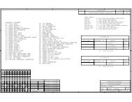
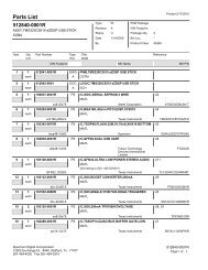
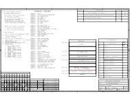
5544332211<strong>Spectrum</strong> <strong>Digital</strong>, IncNOTES, UNLESS OTHERWISE SPECIFIED:1. RESISTANCE VALUES IN OHMS.REV DESCRIPTIONDATE APPROVEDInitial schematic for layout1/10/2011 RRP2. CAPACTITANCE VALUES IN MICROFARADS.3. REFERENCE DESIGNATORS USED:BETA UPDATES 6/19/2011 RRP4. ALL 0.1 uF AND 0.01uF CAPACITORS ARE DECOUPLING CAPS UNLESSPRODUCTION UNITS 7/19/2011 RRPOTHERWISE NOTED. THEY ARE SHOWN ON THE PAGE WITH THE INTEGRATEDCIRCUITS THEY SHOULD BE PLACED NEAR.D DSCHEMATIC CONTENTS01 - TITLE PAGE02 - <strong>TMS320C5535</strong> IO03 - UART BUFFER04 - <strong>TMS320C5535</strong> POWER05 - SPI FLASH06 - CC BOARD INTERFACE07 - MICRO SD INTERFACE08 - POWER SUPPLIES09 - AUDIO CODEC10 - LCD/USER LEDS/SWITCHES11 - EXPANSION CONNECTOR12 - XDS100-v2 INTERFACEC CB BREVISION STATUS OF SHEETSREVDWNDATESHEETR.R.P. 10/15/2009A CHKDATESPECTRUM DIGITAL INCORPORATEDAREVT.W.K. 10/15/2009ENGRDATESHEETR.R.P. 10/15/2009Title:<strong>TMS320C5535</strong> EZDSP MODULEENGR-MGRDATEREV A AR.R.P. 10/15/2009Page Contents: TITLE SHEETQADATESHEET 11 12C.M.D. 10/15/2009Revision:MFGDATESize: BDWG NO 514582-0001CREV C B A A A A A A ANEXT ASSYUSED ONR.R.P. 10/15/2009RLSEDATEDate: Tuesday, July 26, 2011 Sheet 1 o f 13SHEET3 510 APPLICATIONR.R.P. 10/15/20091246789AABCA-2 <strong>TMS320C5535</strong> <strong>eZdsp</strong> <strong>Technical</strong> <strong>Reference</strong> Manual
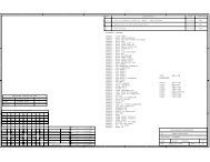
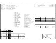
5544332211<strong>Spectrum</strong> <strong>Digital</strong>, IncVCC_3V3_USBFB7TP31 2VBUS VBUS_C5535BLM18AG601SN1D C6C77 C66U4-1120610uF0.1uF 1000pFUSB_VBUSJ1USB_VBUS L14E13USB_VDDOSC1USBVDD10 USB_CLK_12MHZR55 0USB_XIE14USB_DMUSB_M12XIUSB_DM J142USB_DPD- SHIELD163D D+ SHIELD27R56USB_DP H14D4ID SHIELD38NO-POPD14USB_M12XOSHIELD495R54 0USB_R1G14USBVSSD12R29USB_VSSOSCD2C25 C24 R1810K 1%10uFUSBMINI_BUSB_VSSREFF126.2V0.1uF100KGPAIN012 GPAIN0A8GPAIN1GPAIN011,12 GPAIN1B8GPAIN2GPAIN112 GPAIN2A9GPAIN3GPAIN212 GPAIN3A10GPAIN3SD_CLKRSV12G2R68 0I2S0_CLK 12SD_CMDRSV9G1R69 0I2S0_FS 12SD_DATA0RSV8F1R128 0I2S0_DX 12SD_DATA1I2S0_RX 1233pF C91RSV7E1R129 0A7SD_DATA2RSV11E2R130 0RTCXIGPIO4 12SD_DATA3GPIO5 12TP4RSV10H1R131 0CLKOUT32 32.768KHzY1SD_CLKMMC0_CLK/I2S0_CLK/GP[0]M8SD_CLK 6,7SD_CMDC MMC0_CMD/I2S0_FS/GP[1]M10SD_CMD 6,7CR11733pF C90A6SD_DATA0SD_DATA0 6,710KRTCXOMMC0_D0/I2S0_DX/GP[2]J1SD_DATA1MMC0_D1/I2S0_RX/GP[3]P6SD_DATA1 6,7SD_DATA2MMC0_D2/GP[4]N13SD_DATA2 6,7C5SD_DATA3VSS_RTCMMC0_D3/GP[5]P7SD_DATA3 6,713 TARGET_TRSTnP4SPI_RXTRSTNLCD_D[0]/SPI_RX N4SPI_RX 5,6,12SPI_TXVDD_IO1LCD_D[1]/SPI_TX K1SPI_TX 5,6,1213 TARGET_TMSN6GPIO12TMSLCD_D[2]/GP[12]J2GPIO12 6,11,12GPIO13LCD_D[3]/GP[13]N5GPIO13 6,1213 TARGET_TDIK2GPIO14TDILCD_D[4]/GP[14]P2GPIO14 6,11,12GPIO15LCD_D[5]/GP[15]N7GPIO15 3,11,12R2213 TARGET_TDON1GPIO16GPIO16 11,12B R25TDOLCD_D[6]/GP[16]P3GPIO17GPIO17 11,12B10K10KLCD_D[7]/GP[17]P813 TARGET_TCKN3TCKVCC_1V3VDD_IO1C820.1uFTARGET_EMU1TARGET_EMU0I2S2_CLKI2S2_FSI2S2_RXI2S2_DXUART_RTSUART_CTSUART_RXUART_TXSPI_CLKI2S2_CLK 10,12I2S2_FS 10,12I2S2_RX 10,12I2S2_DX 10,12UART_RTS 3,6,12UART_CTS 3,6,12UART_RX 3,6,12UART_TX 3,6,12SPI_CLK 5,6,12VDD_IO1RTC_CLKOUTSPI_CS0RTC_CLKOUTA3SPI_CS0 5,12C83RTC_CLKOUTLCD_CS0_E0/SPI_CS0L1SPI_CS1SPI_CS1 121uF C84WAKEUPLCD_CS_E1/SPI CS1M2A5SPI_CS2SPI_CS2 6,12R140.1uFLCD_RW_WRB/SPI_CS2N2R13WAKEUPR59SPI_CS3VDD_IO1LCD_RS/SPI_CS3M5SPI_CS3 1210K 10K10KB1I2C_SCLINT1I2C_SCLC4I2C_SCL 6,9,10,11,12C2I2C_SDAI2C_SDA 6,9,10,11,12R37 R41INT0I2C_SDA A4D2RESETN100K 100KJ3A XFSPECTRUM DIGITAL INCORPORATEDAC5535Title:<strong>TMS320C5535</strong> EZDSP MODULE9,10,11,13 TARGET_PWR_GOODPage Contents: GPIO,MMC-SD,SPI,I2C,I2SR17 220 DS2 LED_GRNRevision:Size: BDWG NO 514582-0001BDate:Sheet o f Friday, July 22, 2011 2 13651 4CLKOUTA2CLKOUTMMC1_CLK/I2S1_CLK/GP[6]10 CPU_CLK_12MHZR38 0CLKINMMC1_CMD/I2S1_FS/GP[7]C1CLKINMMC1_D0/I2S1_DX/GP[8]CLK_SELMMC1_D1/I2S1_RX/GP[9]CLK_SELD1R34CLK_SELMMC1_D2/GP[10]NO-POPMMC1_D3/GP[11]M14 I2S1_CLKI2S1_CLK 6,12L11 I2S1_FSI2S1_FS 6,12M13 I2S1_DXI2S1_DX 6,12P10 I2S1_RXI2S1_RX 6,12L12 GPIO10GPIO10 6,12M12 GPIO11GPIO11 6,12L2M1C3B4B5EMU0EMU1DVDD_RTCCVDD_RTCCVDD_RTCLCD_D[8]/I2S2_CLK/GP[18]/SPI_CLK P5LCD_D[9]/I2S2_FS/GP[19]/SPI_CS0N10LCD_D[10]/I2S2_RX/GP[20]/SPI_RX P9LCD_D[11]/I2S2_DX/GP[27]/SPI_TX P11LCD_D[12]/UART_RTS/GP[28]/I2S3_CLK N12LCD_D[13]/UART_CTS/GP[29]/I2S3_FS P12LCD_D[14]/UART_RXD/GP[30]/I2S3_RX P13LCD_D[15]/UART_TXD/GP[31]/I2S3_DX M11LCD_EN_RDB/SPI_CLK L3A-3
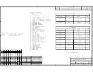
55544332211<strong>Spectrum</strong> <strong>Digital</strong>, IncD DVCC_3V3C390.1uF14C 2,6,12 UART_CTS23TRGT_UART_CTS 13C2,6,12 UART_RX56TRGT_UART_RX 13U5AU5B74CBTLV3125PWR74CBTLV3125PWR174GPIO152,11,12A-4 <strong>TMS320C5535</strong> <strong>eZdsp</strong> <strong>Technical</strong> <strong>Reference</strong> ManualTRGT_UART_RTS 131112UART_RTS2,6,12TRGT_UART_TX 1389UART_TX2,6,1274CBTLV3125PWRU5D74CBTLV3125PWRU5CVCC_3V3B B1310R2410KR133 0UART_BUFF_ENA SPECTRUM DIGITAL INCORPORATEDA<strong>TMS320C5535</strong> EZDSP MODULEUART BUFFERTitle:Page Contents:Revision:DWG NO 514582-0001A13Sheet o f Friday, July 22, 2011 3 Size: BDate:
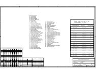
5544332211<strong>Spectrum</strong> <strong>Digital</strong>, IncVCC_1V3R123NO-POPJP1 NO-POPDSP_LDO_OUT_REG2 1DSP_LDO_OUTVCC_1V8R124 0 R20 1 1%R63VCC_3V3_USB FB5U4-2NO-POPD LDO_ENU3D1 2G12C73USB_VDDA3P3VDDA_PLLC7INA219IDCN0.01uF R64C4 C63 C56BLM18AG601SN1DI2C ADDRESS10uF 0.1uFVSSA_PLLA101000pFV_PWR_MONUSB_LDO_OUT 1206100 0000H13USB_VSSA3P3AGNDLDO_ENC27FB4DSP_LDO_EN C130.1uFANA_LDO_OUT1 2BLM18AG601SN1D1206C490.1uFC430.01uFH12J12USB_VDDA1P3USB_VSSA1P3DSP_LDOO A13DSP_LDO_OUT_REGI2C_SCL_PWRAGNDCVDD C11I2C_SCL_PWR 8,9I2C_SDA_PWRFB6I2C_SDA_PWR 8,9AGNDCVDD D3E12USB_VDD1P3CVDD D11F14DSP_LDO_OUTUSB_VDD1P3CVDD F21 2K13USB_VDD1P3CVDD G3C67C46 C52C55CVDD H2C65C89 C42C54C5C60 C74BLM18AG601SN1DCVDD K11K140.1uF0.1uF 1uF0.01uF12061uFUSB_VSS1P3CVDD M60.1uF0.01uF 1uF1uF0.1uF 1000pFC CVDD M9CVCC_3V3_USB L3CVDD N91 2G13USB_VDDPLLRSV1K12BLM18AG601SN1DRSV2L13C3C57 C50C59 C62 C48 C40 C69C38 C53 C41 C64 C51VCC_1V3USB_LDO_OUTU15V_PWR_MONINA219IDCNR121 NO-POPR122 0USB_LDO_OUT_REG D13USB_LDOOI2C ADDRESSANA_LDO_OUTB100 0100BB9C102ANA_LDOORSV4A110.1uFRSV5B11387564GNDA1A0SCLSDAVSVIN+21465783VSSDASCLA0A1GNDVIN+VIN-VIN-12C21uF120610uF0.1uF 1000pFF130.1uF 0.1uF 0.1uF 0.1uF 0.1uF 0.01uF 1uF 0.01uF 1uF 0.01uFUSB_VSSPLLDVDDIO C6VCC_1V8AGNDAGNDDVDDIO L4VCC_3V3_PWRDVDDIO M3VDD_IO1_CPUDVDDIO M4B14NO-POPLDOIDVDDIO N8JP4DVDDIO N111 2C75C14C87 C71LDOIDVDDIO N141 1%R970.1uF 0.1uF 0.1uFB10LDOIR610R600R62NO-POPRSV6ANA_LDO_OUTA12B12B13B7RSV0RSV3RSV6VDDA_ANAVSS A14VSS B2VSS B3VSS C8VSS C12VSS D4VSS D5VSS D10VSS E3VSS E4VSS E11VSS F3C110uFVDD_IO1_CPUC300.1uFC290.1uFC320.1uFC720.1uFI2C_SDA_PWRI2C_SCL_PWRC280.1uFC450.1uFVSS H3VSS J13C86C85C10BG_CAPVSS K31uF0.1uFVSS K4VSS L5A C88VSS L10B6SPECTRUM DIGITAL INCORPORATEDA0.1uFVSSA_ANAVSS M7C9AGNDVSSA_ANAVSS P1VSS P14Title:<strong>TMS320C5535</strong> EZDSP MODULEAGND AGNDC5535FB1Page Contents: <strong>TMS320C5535</strong> POWERTP11 2Revision:BLM18AG601SN1DSize: BDWG NO 514582-0001AGNDAGNDDate: Tuesday, July 26, 2011 Sheet 4 o f 13A-5
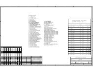
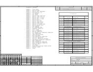
5500441234332211<strong>Spectrum</strong> <strong>Digital</strong>, IncVDD_IO1D R72R73DNO-POPNO-POP2,6,12 SPI_CLK2,6,12 SPI_TXR5210KU9SPI_HOLD1SPI_CLKHOLD SCLK 16VCC_3V32SPI_TXVCC DIO 153NC.3 NC.1414C814NC.4 NC.13130.1uF5NC.5 NC.1212VDD_IO1R51 R50SPI_CS_SW_IN SPI_CS_SW_OUT NO-POP NO-POPR16R71C 6NC.6 NC.1111CR31 NO-POPSPI_CS0_DEVnVDD_IO12,12 SPI_CS07CS GND 10SPI_RX SPI_WP2,6,12 SPI_RX8DO WP 910KR74W25X64VSFIGOR M25P64-VMF6TPR120NO-POPVDD_IO1SW3A-6 <strong>TMS320C5535</strong> <strong>eZdsp</strong> <strong>Technical</strong> <strong>Reference</strong> ManualON8 1CLK_SEL 2B R132 1K7 2UART_BUFF_EN 3B6 3AIC3204I2C_ENn 10SPI_CS_SW_IN 5 4 SPI_CS_SW_OUTDIP_SWITCHR3310KDIP Switch Defaults:CLK_SEL = OFF (pulled down)UART_BUFF_EN = ON (pulled down)AIC3204I2C_ENn = OFF (pulled down)A SPECTRUM DIGITAL INCORPORATEDATitle:<strong>TMS320C5535</strong> EZDSP MODULEPage Contents: SPI FLASHRevision:Size: BDWG NO 514582-0001CDate: Tuesday, July 26, 2011 Sheet 5 o f 13
5544332211<strong>Spectrum</strong> <strong>Digital</strong>, IncD DNOTE: DIMENSIONS AND LOCATIONS OF THESE CONNECTORS MUST MEET SPECIFICATION FOR INTERFACE MODULESP1P312SD_DATA0 2,712VCC_3V32,3,12 UART_RTS34SD_DATA1 2,734RTC_CLKOUT56SD_DATA2 2,7562,3,12 UART_TX78SD_DATA3 2,778 R79 33I2S1_RX 2,12GPIO102,3,12 UART_RX910GPIO10 2,12910 R80 33I2S1_DX 2,12GPIO11C 2,9,10,11,12 I2C_SDA1112GPIO11 2,122,12 I2S1_FS1112C2,9,10,11,12 I2C_SCL1314SPI_CS2 2,122,11,12 GPIO1213142,7 SD_CLK1516SPI_CLK 2,5,122,11,12 GPIO14R66 33 15162,7 SD_CMD1718SPI_TX 2,5,122,12 I2S1_CLK1718 R81 33UART_CTS 2,3,121920R67 33R82 33SPI_RX 2,5,121920GPIO13 2,12HEADER 10X2HEADER 10X2B BA SPECTRUM DIGITAL INCORPORATEDATitle:<strong>TMS320C5535</strong> EZDSP MODULEPage Contents:CC BOARD INTERFACERevision:Size: BDWG NO 514582-0001ADate:Sheet o f Friday, July 22, 2011 6 132A-7
5544332211<strong>Spectrum</strong> <strong>Digital</strong>, IncVCC_3V3VCC_3V3 VCC_3V3D DR103 R102 R101 R100 R99 R98C1510K 10K NO-POP 10K 10K 10KC10610uF 0.1uFR10910K2,6 SD_DATA2SD_DATA21SD_DATA3DAT22,6 SD_DATA32SD_CMDDAT32,6 SD_CMD3CMD42,6 SD_CLKSD_CLKVDD5CLK62,6 SD_DATA0SD_DATA0VSS72,6 SD_DATA1SD_DATA1DAT08DAT1INSERT9J6INSERT_COM 10MicroSD_CARDC CB BA SPECTRUM DIGITAL INCORPORATEDATitle:<strong>TMS320C5535</strong> EZDSP MODULEPage Contents:MICRO SD CONNECTORRevision:Size: BDWG NO 514582-0001ADate:Sheet o f Friday, July 22, 2011 7 13+11111413121413121515A-8 <strong>TMS320C5535</strong> <strong>eZdsp</strong> <strong>Technical</strong> <strong>Reference</strong> Manual
5544332211<strong>Spectrum</strong> <strong>Digital</strong>, IncVCC_USB_DUALU1TP2VCC_1V8_TPVCC_1V8SW 51VIN1L6 2.2uHD DR118 02C23C22GND4.7uF.1uF3EN FB 4TPS62260DDCTR113.60K 1%C1242200pFC2110uFC123.1uF4.7uFR151.80K 1%Vout = Vref x ( 1 + Rtop/RBottom ) ; VREF = 0.6Vout = 0.6 x ( 1 + 2 )C FTDI_3V3CR1 0C20VDD_IO1TP5R119 0VCC_3V3_TPVCC_USB_DUAL VCC_3V3_PWRVCC_3V3U12SW 51VIN1L7 2.2uHR2 0C994.7uFC97.1uF23GNDENFB 4TPS62260DDCTR658.06K 1%C1252200pFC9410uFJP521NO-POPC1004.7uFVCC_3V3_USBB R96 1 1%BR70Vout = Vref x ( 1 + Rtop/RBottom ) ; VREF = 0.6Vout = 0.6 x ( 1 +4.47 )1.80K 1%V_PWR_MONU16INA219IDCNI2C ADDRESS100 1000465783VSSDASCLA0A1GNDVIN+VIN-12C1010.1uFI2C_SCL_PWRI2C_SDA_PWRI2C_SCL_PWR 4,9I2C_SDA_PWR 4,9A SPECTRUM DIGITAL INCORPORATEDATitle:<strong>TMS320C5535</strong> EZDSP MODULEPage Contents:POWER MANAGEMENTRevision:Size: BDWG NO 514582-0001CDate:Sheet o f Tuesday, July 26, 2011 8 13A-9
5544332211<strong>Spectrum</strong> <strong>Digital</strong>, IncD DTP7VCC_1V3_TPVCC_3V3_PWRVCC_1V3U115IN1 OUT176IN2 OUT28C984R125+ C95 + C264.7uFEN FB 14.7uF4.7uF310.7KGND PG 2 VCC_3V3_PWRTPS76601R126CR127169K 1%C220KRF1 = ( Vout/Vref - 1) * RF2RF1 = ( 1.3/1.224 - 1) * 169KTARGET_PWR_GOOD 2,10,11,13VCC_3V3_PWR V_PWR_MONR87 0B BR85R83NO-POP NO-POPI2C_SCL_PWRI2C_SCL_PWR 4,8I2C_SDA_PWRI2C_SDA_PWR 4,8JP3R861I2C_SDA 2,6,10,11,12R842I2C_SCL 2,6,10,11,123HEADER 3Power Monitor I2C Probe Point HeadersA SPECTRUM DIGITAL INCORPORATEDATitle:<strong>TMS320C5535</strong> EZDSP MODULEPage Contents:POWER MANAGEMENTRevision:Size: BDWG NO 514582-0001ADate:Sheet o f Friday, July 22, 2011 9 1300A-10 <strong>TMS320C5535</strong> <strong>eZdsp</strong> <strong>Technical</strong> <strong>Reference</strong> Manual
5544335220011<strong>Spectrum</strong> <strong>Digital</strong>, IncVCC_1V8VCC_1V80R107 NO-POPR106 NO-POPC11 C108C116 C1910uF 0.1uF0.1uF 10uFJP6JP7VCC_3V31 2GND-AIC2 1 V3.3AD DR5 0R108 0C8 C105C111 C1210uF 0.1uF0.1uF 10uFVCC_3V3VCC_3V3U17GND-AICR110STEREO IN 11KTLV320AIC3204IRHBTC122R141 R137.1uFU18J32C17no-pop 220K2040.47uFVCC5AIC_RSTTARGET_PWR_GOOD 2,9,11,13C16RESET31R8 0181B 1A 2319I2S2_CLK 2,1210.47uFMICBIAS172B 2A 313IN1_L163B 3A 4I2S2_FS 2,1214I2S2_DX 2,12AIC_LINE2LIN1_R1515AIC_IISCLKI2S2_RX 2,12GND-AICAIC_LINE2RIN2_LBCLK 2R92 04B 4A 514R11116AIC_IISFSR93 0I2C_SCLI2C_SCL 2,6,9,11,12SJ1-3515-SMT, 5PJACK STEREOIN2_RWCLK 35B 5A 613AIC_IISD0R94 0I2C_SDAC 1K20IN3_LDIN 46B 6A 712I2C_SDA 2,6,9,11,12C21AIC_IISD1IN3_RDOUT5R95 07B 7A 8118B 8A 9AVDD 24LDO_IN 26IOVDD 6DVDD 2998MCLK 1HEADPHONE_LOUTHEADPHONE_ROUTGND-AICNC 1OE 19VCC_3V3GND10910SCL/SSZSDA/MOSIHPLHPRLOLLOR25272223SN74CBTLV3245APWRR13810KR13510KAIC_MODE_SELSPI_SEL12MISO 11SCLK/MIC_DET8LDO_SELGPIO3032R13410KHEADPHONES OUTR1044.7KC14 100uFCONN_HP_LOUTREF18J4+I2C_SCL_AICI2C_SDA_AICAVSSPPADIOVSSDVSSC1170.1uFC1810uFC13 100uFCONN_HP_ROUT+24531AIC3204I2C_ENn173372898GND-AICGND-AICSJ1-3515-SMT, 5PJACK STEREOR136VCC_3V3B BVCC_3V310KGND-AICC1040.1uFI2C ADDRESS001 1000R10 4.7KU14R9NO-POP4VCC OFFn1Select Internal LDOR7 1003CLK GND 2ASDM1-12.000MHZ-LC-TR91CLK_12MHZ 13R90V3.3AVCC_3V3USB_CLK_12MHZ 2FB3R89CPU_CLK_12MHZ 21 2BLM21AG151SN1DA SPECTRUM DIGITAL INCORPORATEDATie Analog Power to <strong>Digital</strong> Power through singlepoint connection or Ferrite Bead.TP6Title:<strong>TMS320C5535</strong> EZDSP MODULEFB2Page Contents: CODECGND1 2BLM21AG151SN1DRevision:Size: BDWG NO 514582-0001AGND-AICDate: Friday, July 22, 2011 Sheet 10 o f 13A-11
5544332211<strong>Spectrum</strong> <strong>Digital</strong>, IncJ51ANA_LDO_OUTC109C2P1uF2R113C2N10KVCC_3V33C110C1PD SW1R105 NO-POPD1uF1 2 R116 20KR114 100GPAIN1 2,124C113C1N3 4C1121uF.1uFUSER1C121NO-POP5VBAT0SD9616GLBBG016VBREFVCC_3V3SW2C1151 2 R115 10K7VSS3 4.022uFUSER2C118 C114.1uF 1uF8VDD2,9,10,13 TARGET_PWR_GOOD9RESnC CVCC_3V32,6,9,10,12 I2C_SCL10SCLU10ASN74LV125C96.1uFVCC_3V32,6,9,10,12 I2C_SDA11SDA2,6,12 GPIO1423LED0R75 220 DS6 LED BLUER112 392K 1%12IREFR76 220DS5 LED YELLOW13R77 220 DS4 LED REDVCOMHV13U10BSN74LV125R78 220 DS3 LED GRN14C119VCC2,3,12 GPIO1556LED12.2uFC1202.2uFFCI_10051922-1410ELFB BVCC_USB_DUALU10CSN74LV125R88 02,12 GPIO1698LED2LCD POWER 13VL2 2.2uHMBR0520 C107R6 C103U10DSN74LV1252,12 GPIO171211LED3C1010uF1341714D110U131uF1.6M 1% 10pF5Vin SW 1C9GND 210uF,16VR44EN FB 3180K 1%TPS61041A SPECTRUM DIGITAL INCORPORATEDA2,6,12 GPIO12R3Title:<strong>TMS320C5535</strong> EZDSP MODULE10KPage Contents: LCD INTERFACERevision:Size: BDWG NO 514582-0001ADate:Sheet o f Friday, July 22, 2011 11 13A-12 <strong>TMS320C5535</strong> <strong>eZdsp</strong> <strong>Technical</strong> <strong>Reference</strong> Manual
5544332211<strong>Spectrum</strong> <strong>Digital</strong>, IncD DVCC_USB_DUALVCC_3V3EDGE CONN 30X260 595857GPAIN05655SPI_CS0SPI_CS0 2,52,11 GPAIN15453SPI_CS2SPI_CS2 2,6GPAIN25251I2S0_FSI2S0_FS 2GPAIN35049I2S0_DXI2S0_DX 24847I2S0_RXI2S0_RX 2SPI_CS3SPI_CS34645I2S0_CLKI2S0_CLK 2444342412,3,6 UART_TXUART_TX4039I2S1_FSI2S1_FS 2,62,3,6 UART_RXUART_RX3837I2S1_DXI2S1_DX 2,62,3,6 UART_CTSUART_CTS3635I2S1_RXI2S1_RX 2,62,3,6 UART_RTSUART_RTS3433I2S1_CLKI2S1_CLK 2,63231I2S2_FSC GPIO43029I2S2_FS 2,10CGPIO52827I2S2_DXI2S2_DX 2,102,6 GPIO10GPIO102625I2S2_RXI2S2_RX 2,102,6 GPIO11GPIO112423I2S2_CLKI2S2_CLK 2,102,112,112,3,112,6,112,6,11GPIO17GPIO16GPIO15GPIO14GPIO12GPIO172019I2C_SCLGPIO161817I2C_SDA161514131211GPIO15109SPI_RXGPIO1487SPI_TXGPIO1265SPI_CLKGPIO13 SPI_CS1I2C_SCL 2,6,9,10,11I2C_SDA 2,6,9,10,11SPI_RX 2,5,6SPI_TX 2,5,6SPI_CLK 2,5,62,6 GPIO13SPI_CS1 24231P2B BA SPECTRUM DIGITAL INCORPORATEDATitle:<strong>TMS320C5535</strong> EZDSP MODULEPage Contents:EXPANSION CONNECTORSRevision:Size: BDWG NO 514582-0001ADate:Sheet o f Friday, July 22, 2011 12 13222222A-13
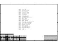
<strong>Spectrum</strong> <strong>Digital</strong>, IncC3710nFJ25V_USB 1D-2D+3GND 4USB-A PLUG10CLK_12MHZMounting holes 0.250 pad 0.125 drillFTDI_3V3XTINU2VCC CS 1NC1 SK 2NC2 DIN 3GND DOUT4876593C46_56_66VCCUSB PLACE BY EMU USB CONNECTORVBUS_C5535D3D4JP21 2VCCUSBC710uFFTDI_3V3L5FTDI_3V3CON2C35100nFVCC_USB_DUALPLACE BY C5535 USB CONNECTORC70C80100nF100nFC44 4.7uFC36C79100nF100nFC47 100nFC33C58C76 4.7uF10nF10nFFT1.8VFT1.8VTCKR39 47 TARGET_TCKTARGET_TCK 2R26NO-POPFTDI_3V3R36 10KSRST_N_OUTEMU_ENEMU0PWR_DETPWR_RSTEMU1R45 47-NOPOPTRGT_UART_RX 3TRGT_UART_TX 3TRGT_UART_CTS 3TRGT_UART_RTS 3TDITDOTMSTRSTNRTCKDISSRST_N_INR47 4747-NOPOPR44 10KTARGET_TDITARGET_TDOTARGET_TMSTARGET_TRSTnC78.1uFFTDI_3V3FTDI_3V3TARGET_TDI 2TARGET_TDO 2TARGET_TMS 2TARGET_TRSTn 22,9,10,11TARGET_PWR_GOODOPTIONAL: IF NOT USED CONNECTPWR_GOOD TO PWR_DET.VCC_USB_DUALEECSEESKEEDATAGREENLOCATE LED ALONG A BOARDEDGE SO IT WILL BE MOREVISIBLE.Title:Page Contents:SPECTRUM DIGITAL INCORPORATED<strong>TMS320C5535</strong> EZDSP MODULEXDS100-V2 INTERFACERevision:Size: BDWG NO 514582-0001AR21 2K2Date: Sheet of Friday, July 22, 2011 13 136S1S25BLM21P221SNC31100nFR23 0C92100nFL4BLM21P221SN1Z1 1 Z2L1BLM21P221SNC34 100nFC61 100nFR28 12K 1%4914363626113VREGOUTRESET#XTOUTEECSEESKEEDATATESTR35 0R32 0R30 0R27 0R49 47R58 47R43 10K123U8CLKGNDDCLR 6VCC 5Q 474LVC1G175-DBV6AGNDU6 FT2232HL1015111525354751GND.1GND.2GND.3GND.4GND.5GND.6GND.7GND.8VPHY 4VPLLVCORE.1VCORE.2VCORE.3VCCIO.1VCCIO.2VCCIO.3VCCIO.49123764203142561Z3 1 Z4C9310nFU7IO4VCC 15NC 2GND IO134TPD2E001R19 10KMBR0520C68100nFMBR0520507862VREGINDMDPREFXTINADBUS0ADBUS1ADBUS2ADBUS3ADBUS4ADBUS5ADBUS6ADBUS7ACBUS0ACBUS1ACBUS2ACBUS3ACBUS4ACBUS5ACBUS6ACBUS7BDBUS0BDBUS1BDBUS2BDBUS3BDBUS4BDBUS5BDBUS6BDBUS7BCBUS0BCBUS1BCBUS2BCBUS3BCBUS4BCBUS5BCBUS6BCBUS71617181921222324262728293032333438394041434445464852535455575859R46R53 47R48 47R57R4210K10KR40 NO-POPPWREN#SUSPEND#6036R12DS1220A-14 <strong>TMS320C5535</strong> <strong>eZdsp</strong> <strong>Technical</strong> <strong>Reference</strong> Manual
Appendix BMechanical InformationThis appendix contains the mechanical information about the<strong>TMS320C5535</strong> <strong>eZdsp</strong> produced by <strong>Spectrum</strong> <strong>Digital</strong>.B-1
<strong>Spectrum</strong> <strong>Digital</strong>, IncTHIS DRAWING IS NOT TO SCALEALL MEASUREMENTS ARE IN INCHESB-2 <strong>TMS320C5535</strong> <strong>eZdsp</strong> <strong>Technical</strong> <strong>Reference</strong> Manual
Printed in U.S.A., August 2011514585-0001 Rev. A