Quintessenza Book - Biomet 3i
Quintessenza Book - Biomet 3i
Quintessenza Book - Biomet 3i

You also want an ePaper? Increase the reach of your titles
YUMPU automatically turns print PDFs into web optimized ePapers that Google loves.
Global Headquarters4555 Riverside DrivePalm Beach Gardens, FL 334101-800-342-5454Outside The U.S.: +1-561-776-6700Fax: +1-561-776-1272www.biomet<strong>3i</strong>.comSign Up For BIOMET <strong>3i</strong>’s Electronic Newsletter “BIOMET <strong>3i</strong>nnovations.”Simply Go Online To www.biomet<strong>3i</strong>.com/signupBone Bonding, Certain, Encode, EP, GingiHue, Gold-Tite, OSSEOTITE, PreFormance, PREVAIL, QuickSeat andZiReal are registered trademarks and DCD, NanoTite and RegenerOss are trademarks of BIOMET <strong>3i</strong>, LLC. BIOMETis a registered trademark and BIOMET <strong>3i</strong> and design are trademarks of BIOMET, Inc. Denzir and Cad.EstheticsSystem are registered trademarks of Cad.Esthetics AB. Ceram X is a trademark of DENTSPLY. Dimension,Penta, Protemp and RelyX are trademarks of 3M ESPE. Empress is a registered trademark of Ivoclar Vivadent, Inc.Osstell and Smartpeg are trademarks of Integration Diagnostics. ©2008 BIOMET <strong>3i</strong>, LLC. All rights reserved.Rev A 05/08QUINTESSENZA INTERNAZIONALE 3 BIS/2008Q eQUINTESSENZA INTERNAZIONALEQUINTESSENZA EDIZIONI S.r.l. - Via Ciro Menotti 65 - 20017 Rho (Mi) - Sped. in abb. post. D.L. 353/2003 (conv. in L. 27/02/04 n. 46) art. 1 comma 1, DCB - MilanoMAY - JUNE 2008 Y E A R 2 4The NanoTite Implant:A Nanotechnology-BasedBone Bonding ® * ImplantPublication Supported by:BIOMET <strong>3i</strong>Clinically relevant, scientifically basedNUMBER 3 BIS* Bone Bonding is the interlocking of the newly formed cement line matrix of bone with the implant surface.
A Reflection OfThe Latest AdvancementIn Implant Dentistry –The NanoTite Tapered Implant
*The interlocking of the newly formed cement linematrix of bone with the implant surface.
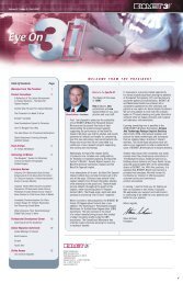
QUINTESSENZA INTERNAZIONALEISSN 1723-7793Editor in ChiefProf. Giacomo UrbaniEditorsDr.ssa Lilia BortolottiProf. Enrico ConservaProf. Matteo D’AngeloProf. Massimo De LucaDr. Massimo De SanctisDr. Mauro FradeaniDr. Luigi GalassoDr. Stefano GracisDr. Salvatore LongoniDr. Domenico MassironiDr. Marco MorraProf. Giovanni Paolo Pini PratoProf. Sergio TartaroPublisher<strong>Quintessenza</strong> Edizioni nella persona diHorst-Wolfgang HaaseGeneral ManagerLauro DusettiPublishing DirectorCristina ReinaMarketing and AdvertisingLauro Dusetti (Manager) Cell. 338 9312741l.dusetti@quintessenzaedizioni.itSilvia Fassettis.fassetti@quintessenzaedizioni.itLayout/ProductionCristina Reinac.reina@quintessenzaedizioni.itBarbara Rossib.rossi@quintessenzaedizioni.itDr. ssa Lilia BortolottiDr. Ezio BrunaProf. Antonio CarrassiDr. Gianfranco CarnevaleDr. Raffaele CavalcantiProf. Ugo ConsoloProf. Gianpiero CordioliDr. Sergio De PaoliDr. Massimo De SanctisProf. Giuseppe FerronatoDr. Mauro FradeaniSig. Giancarlo GarottiSig. Guido GarottiSubscription rate (Italy)2008: euro 120,00COMPANY ADDRESS<strong>Quintessenza</strong> Edizioni s.r.l.via Ciro Menotti 6520017 - Rho, Milano - ITALYTel. +39 (2) 93.18.08.21c.c. post. n. 35326438Editorial BoardProf. Enrico GherloneDr. Stefano GracisDr. Salvatore LongoniDr. Massimiliano MartignoniDr. Marco MorraProf. Pierfrancesco NociniDr. Stefano Parma BenfenatiDr. Roberto PontorieroProf. Loris ProsperDr. Antonio RocciProf. Massimo SimionProf. Giacomo UrbaniSubscriptionMaria Calabresem.calabrese@quintessenzaedizioni.itMarta Verganim.vergani@quintessenzaedizioni.itAdministrationMaria Calabresem.calabrese@quintessenzaedizioni.itEventsLauro Dusettil.dusetti@quintessenzaedizioni.itSilvia Fassettis.fassetti@quintessenzaedizioni.itMarta Verganim.vergani@quintessenzaedizioni.itQUINTESSENZA INTERNAZIONALEis published bimonthly in italian language by <strong>Quintessenza</strong>Edizioni s.r.l., via Ciro Menotti 65 - 20017Rho, Milano, ITALY.COPYRIGHT © 2008 by Quintessence PublishingCo. Ltd. All rights reserved.No part of this journal may be reproduced in anymaterial form (including photocopying or storing it inany medium by electronic means and whethertransiently or incidentally to some other use of thisjournal), without the written permission of thepublisher. Application for the copyright owner’swritten permission to reproduce any part of thisjournal should be addressed to the publisher. Thepublisher assumes no responsibility for unsolicitedmanuscripts. All opinions are those of the authors.Printed in ItalyReg. Trib. Milano n. 511 del 16-09-03Sped. in A.P. D.L. 353/2003 (conv. in L. 27/02/04 n. 46)art. 1 comma 1, DCB - MilanoQuesto periodico è associatoall’Unione Stampa Periodica Italiana
QUINTESSENZA INTERNAZIONALECONTENTS6 PrefaceJ. E. DaviesSurface Characterization Studies9 Dissolution Of Discrete Calcium Phosphate Crystals From Candidate Ti-Based ImplantSurfacesP. Pezeshki, S. Lugowski, J. E. Davies11 Surface Area Increase Due To Discrete Crystalline Deposition Of Nanometer-scaleCaP CrystalsZ. Suttin, P. Gubbi12 Roughness Characterization Of Surface With Discrete Crystalline DepositionOf Nanometer-scale CaP CrystalsP. Gubbi, Z. Suttin, A. Goolik13 Adhesion Shear Strength Of Nanometer-scale CaP Crystals AppliedBy Discrete Crystalline DepositionZ. Suttin, P. Gubbi14 Determination Of CaP Crystal Shear Strength Using Contact-Mode Atomic ForceMicroscopy (AFM)G. Shekhawat, Z. Suttin17 Qualitative Evaluation Of Crystal Adhesion During Implant Placement in Simulated BoneMediumZ. Suttin19 Modeling Interfacial Shear Strength At A CAP-Modified Titanium And BoneC. Pan, J. Chau, V. C. Mendes, C. A. Simmons, J. E. Davies21 Chemical And X-ray Diffraction Analyses Of Calcium Phosphate Used For DiscreteCrystalline DepositionR. M. Stach, P. Gubbi, Z. Suttin23Hydrophobic/Hydrophilic Characteristic Of Titanium Surfaces: Machined, Dual AcidEtched (OSSEOTITE ® ), And Dual Acid Etched With Nanometer-Scale CaP (NanoTite)P. Gubbi, R. Towse, B. Berckmans
QUINTESSENZA INTERNAZIONALECONTENTS25Qualitative And Quantitative Analyses Of NanoTite TM Surfaced ImplantsP. Gubbi, R. TowsePreclinical Studies28 Implants Treated With Discrete Crystalline Depositions Of Nanometer-Scale CalciumPhosphate Crystals Enhance Early Implant-Bone Fixation In A Rat Femur Push-In ModelI. Nishimura, A. Lin, C. J. Wang, J. Kelly30Nanometer-scale CaP Enhances Early Implant-Bone Fixation In An Animal ModelJ. N. Kenealy, PharmD, B. Berckmans, R. M. Stach31 Discrete Calcium Phosphate Nanocrystalline Deposition Enhances Osteoconduction OnTitanium-based Implant SurfacesV. C. Mendes, J. E. Davies32Discrete Calcium Phosphate Nanocrystals Render Titanium Surfaces Bone BondingV. C. Mendes, J. E. Davies35Discrete Calcium Phosphate Nanocrystals Enhance Osteoconduction On Titanium-basedImplant SurfacesV. C. Mendes, J. E. Davies38Discrete Calcium Phosphate Nanocrystals Render Titanium Surfaces Bone BondingV. C. Mendes, J. E. Davies39Discrete Deposition Of Hydroxyapatite Nanoparticles On A Titanium Implant WithPredisposing Substrate Microtopography Accelerated OsseointegrationI. Nishimura, F. Butz, T. Ogawa, A. Lin, C. J. Wang41 Discrete Deposition Of Calcium Phosphate Nanocrystals Promotes Bone-Bonding OnTitanium SurfacesV. C. Mendes, R. Moineddin, J. E. DaviesClinical Studies44Randomized, Controlled Histologic And Histomorphometric Evaluation Of Implants WithNanometer-Scale Calcium Phosphate Added To The Dual Acid-Etched SurfaceIn The Human Posterior MaxillaG Orsini, M Piattelli, A Scarano, G Petrone, A Piattelli, S Caputi
QUINTESSENZA INTERNAZIONALECONTENTS46Influence Of A Nanometer-Scale Surface Enhancement On De Novo Bone Formation OnTitanium Implants: A Histomorphometric Study In Human MaxillaeR. J. Goené, T. Testori, P. Trisi47 Overview: Studies In ProgressClinical Perspectives68 NanoTite Implants: The Next Generation Of Dental ImplantsR. J. Lazzara70Immediate Loading Of Two NanoTite PREVAIL ® Implants With PreFormance ®Provisional ComponentsR. Cocchetto74 Immediate Placement Of A NanoTite PREVAIL ® Implant With Simultaneous GraftingH. S. Baumgarten78Sinus Lift, Immediate Placement/Provisionalization With NanoTite PREVAIL ® ImplantsIn The Posterior MaxillaR. Emery82Placement Of A Short Length NanoTite PREVAIL ® Implant In The Maxillary PosteriorRegion To Avoid A Sinus Lift*P.-O. Östman86Immediate Provisionalization Of A NanoTite PREVAIL ® Implant In The Aesthetic Zone:A Case PresentationP.-O. Östman92Post-extractive Implant With Early Loading In A Highly Aesthetic AreaT. Testori, L. Fumagalli, A. Parenti95Placement Of A Post-extractive Implant With Early Loading In The Central RegionR. J. Goené97 Total Rehabilitation Of A Post-extractive Lower Jaw With The Insertion Of AngledImplants And The Use Of An Immediate Loading Toronto BridgeT. Tealdo, M. Bevilacqua, P. Pera100 Immediate Loading In The Lateral-posterior AreasF. Zuffetti, M. Capelli, F. Galli
QUINTESSENZA INTERNAZIONALEPrefaceJohn E. Davies, BDS, PhD, DSc, FSBEThroughout the last decade ithas become increasingly evidentthat changing the microtexture ofan implant surface will haveprofound effects on the earlystages of peri-implant healing.For this reason the predominantfocus of numerous studies, frommany research groups, has beenthe acceleration of contactosteogenesis, within theframework of accelerating early implantstabilization. Thus microtextured implants, asexemplified by the OSSEOTITE ® Implantsurface, have become the treatment of choicein current dental implant practice.However, while robust experimentalevidence shows that increasing implantmicrotopography can, indeed, acceleratecontact osteogenesis, the nature of theinterface between bone and the implantsurface has not been the focus of greatattention. This is surprising, as we know fromfundamental bone biology that the mechanicalstability of such an interface is crucial to thepractical benefits of increased osteoconduction.Thus, while current microtextured implantsurfaces are osteoconductive, there is nobonding of the bone to the implant surface, ashappens at remodeling sites in normal bone.Indeed, the bone/bone interface formed duringnormal remodeling provides an ideal paradigmfor both osteoconduction andbone bonding.These two phenomena,and the importance of earlymechanical stability havebeen particularly emphasizedin the calcium phosphateliterature where it has been longknown that Bone Bonding ® tosuch surfaces can generate amechanically efficient interfacethat withstands loading, and results in radicallyincreased stability of the implant in situ.Nowhere is this more important than the clinicalscenario where early loading is considered amajor clinical advantage in both dentistry andorthopedics. Thus, if early contact osteogenesisoccurs, together with the bonding of the newlyformed bone to the implant surface, then theestablishment of a more robust implant/boneinterface can result in a distinct advantage topatient treatment.This is by far the most exciting aspect ofthe new NanoTite Surface since it bothincreases osteoconduction over the alreadyexcellent performance of the OSSEOTITEImplant, and is inherently Bone Bonding. Thischaracter is illustrated in the Figure whichshows the surface of a rectangular NanoTiteImplant following retrieval from bone which,following a mechanical disruption test, is stillclearly adherent to the implant surface. WhenFig. 1 Adhesion of bone to the NanoTite Surface aftera separation test.6 YEAR 24 • NUMBER 3 bis • MAY/JUNE 2008
QUINTESSENZA INTERNAZIONALEJohn E. Davies, BDS, PhD, DSc, FSBEnew bone forms at a bone remodeling site, orby contact osteogenesis on an implant surface,a collagen free cement line matrix occupies theinterface. We now understand that the bondingof new bone to old bone is due to the intimateinterdigitation, and interlocking, of the cementline matrix with the underlying surface. Bonebonds to NanoTite Surfaces by this samemechanism that makes NanoTite a uniquesurface, unlike other current implant surfacemodifications, and heralds a new era in thedevelopment of advanced dental implantsurface design.This dossier provides a review of laboratory,animal and clinical data accumulated to dateusing NanoTite Implant Surfaces.BiographyJohn E. Davies, BDS, PhD, DSc, FSBEDr. Davies received his Doctor of Sciencedegree from the University of London and isProfessor of Dentistry and Biomaterials at theUniversity of Toronto, Toronto, Ontario, Canada,specializing in research of periimplant bonehealing and bone tissue engineering. He is alsoa member of the Institute of Biomaterials andBiomedical Engineering and Director of TheBone Interface Group.YEAR 24 • NUMBER 3 bis • MAY/JUNE 2008 7
Surface Characterization Studies
QUINTESSENZA INTERNAZIONALESurface Characterization StudiesDissolution Of Discrete Calcium Phosphate CrystalsFrom Candidate Ti-Based Implant SurfacesPadina Pezeshki, Stanley Lugowski And John E. Davies, Faculty Of Dentistry,University Of Toronto, Toronto, ON, Institute Of Biomaterials And BiomedicalEngineering, University Of Toronto, Toronto, ONSociety For Biomaterials32nd Annual Meeting (April 18-21, 2007, Chicago, IL, USA)STATEMENT OF PURPOSEPlasma-spraying of bone implants with CaPaccelerates peri-implant healing and rendersimplant surfaces bone bonding. Clinicalsuccess has been achieved, but problemshave also been identified due to disintegrationand delamination of thick (∼ 50 μm) coatings 1 .Also, the associated high temperature, resultsin a heterogeneous coating comprising severalsurfaces with CaP comprises deposition ofdiscrete crystals (DCD) of CaP (20-100 nm)onto the metal surface. Our current study wasdesigned to quantify the amount anddissolution kinetics of these discrete CaPcrystals from dental implant surfaces andcompare their behavior with commerciallyavailableplasma sprayed CaP coated implantsof a similar size. We chose an investigationalpH range of 4-7 for our experiments.METHODSFig. 1 Comparison of total [Ca] on plasma sprayed andDCD-treated implants.CaP phases 2,3 . Thus, the solubility of coatingshas been a subject of considerable study, anddifferent fabrication methods have aimed tomodify the properties that influence the CaPdissolution rate. A recent means of modifyingDCD-treated implants (6 mm Ø x 15 mmL)and plasma sprayed CaP implants (6 mm Ø x13 mmL) were supplied by BIOMET <strong>3i</strong> (PalmBeach Gardens, FL). The experiments measured(i) total amount of Ca on the surface and (ii)amount of Ca released in pH-specificsolutions. All experimental equipment wasinitially cleaned to remove containing Cacontaminants. For determination of total Ca,each DCD-treated implant was immersed in10 ml of 1 M Ultrex Grade HCl (pH 0) for 15min and each plasma sprayed sample for 16hrs (n = 8). For the second part of theexperiment, samples were placed in 10 ml ofsaline solution with fixed pH of 4, 5, 6, or 7 for15 min (n=3).The samples were then removed and the totalCa in the remaining solution was measuredusing atomic absorption spectrophotometry.Furthermore, the morphology of the surfaceswas qualitatively analyzed using field emissionscanning electron microscopy.YEAR 24 • NUMBER 3 bis • MAY/JUNE 2008 9
QUINTESSENZA INTERNAZIONALEP. Pezeshki, S. Lugowski, J. E. Daviesoccur from plasma sprayed implants. Finally,the pH-dependent dissolution of the twoimplant types demonstrated that the DCD hadan homogeneous CaP phase while plasmasprayed samples were multi-phasic.CONCLUSIONSFig. 2 Dissolution trends of plasma sprayed and DCD-treated implants.DCD-treatment provides the surface withthe advantages of CaP while utilizing over3000 times lower coverage than traditionalplasma spraying. The treatment also retains ahomogenous and stable phase of CaPcompared to the more soluble and henceundesirable multi-phase CaP coverage achievedthrough plasma spraying.RESULTS AND DISCUSSIONACKNOWLEDGEMENTSThe results showed that DCD-treatedimplants had 3 orders of magnitude less CaPthan plasma sprayed implants. As DCDtreatmentis not a coating, delamination is nota potential problem, and as the crystals are ofthe nanometer scale range, should theybecome detached from the implant surface theycan be easily phagocytosed by cells anddegraded. Dissolution per unit time showed aninverse relationship with pH. This is relevant tothe initial steps of biological healing, whereactivated macrophages, which randomlycontact the implant surface, reduce the localpH to 4. However, at normal body pH of 7.4, thedissolution of CaP from DCD implants isalmost zero, while dissolution continues toWe are grateful for financial support fromBIOMET <strong>3i</strong> and the Ontario Research andDevelopment Challenge Fund (ORDCF).REFERENCES1 Sun et al., J Biomed Mater Res. 2001;58(5):570-92.2 Yang et al., J Biomaterials 2005;26:327-337.3 Zeng et al., J Biomaterials 1999;20(5):443-351.10 YEAR 24 • NUMBER 3 bis • MAY/JUNE 2008
QUINTESSENZA INTERNAZIONALESurface Area Increase Due To Discrete CrystallineDeposition Of Nanometer-scale CaP CrystalsZach Suttin, Prabhu Gubbi, BIOMET <strong>3i</strong>, Palm Beach Gardens, Florida, USAEuropean Association For Osseointegration15th Annual Meeting (October 5–7, 2006, Zurich, Switzerland)INTRODUCTIONThis study estimates the increase in surfacearea (SA) due to the deposition of nano-scalecalcium phosphate (CaP) crystals onto a dualacid-etched(DAE) implant surface.MATERIALSAND METHODScrystals onto a DAE surface. The size, shapeand distribution of the nano-CaP crystals werebased on the dimensions obtained fromFESEM (JEOL Model 6700F) images. Thecrystals were modeled as ellipsoids with sizesranging from 20-80 nm on the long axis and10-39 nm on the short axis. Based on theFESEM imaging, the distributions of crystalcoverage considered for the analysis wereclassified as light (25-30%), medium (55-60%)and heavy (65-70%).Atomic Force Microscopy (AFM) is used toquantify surface measurement parameters ofsurfaces with nanometer topographicalcharacteristics. In addition to the AFM datacurrently being generated, this study usestheoretical 3-D modeling to estimate the SAincrease due to the deposition of nano-CaPRESULTSAND DISCUSSIONThe calculated estimates for SA increasedue to nano-CaP deposition were 84%, 152%and 264% for the light, medium and heavycrystal coverage, respectively. Furthermore,compared to a machined surface, the DAEtreatment increases the implant SA > 50% (dataon file), and it was estimated that the increasein implant SA with the addition of nano-CaPonto the DAE surface ranges from 176% to446%.CONCLUSIONFig. 1 Increase of surface area, related to crystals coveragelevel.Deposition of nano-scale CaP crystals overa micron-scale DAE surface significantlyincreases the overall SA and topographicalcomplexity.YEAR 24 • NUMBER 3 bis • MAY/JUNE 2008 11
QUINTESSENZA INTERNAZIONALERoughness Characterization Of SurfaceWith Discrete Crystalline DepositionOf Nanometer-scale CaP CrystalsPrabhu Gubbi, Zach Suttin, Alexis Goolik, BIOMET <strong>3i</strong>, Palm BeachGardens, Florida, USAAcademy Of Osseointegration22nd Annual Meeting (March 8-10, 2007, San Antonio, Texas)INTRODUCTIONThe objective of this study was to characterizethe surface roughness of polished titanium diskswith nanometer-scale calcium phosphate (CaP)crystals deposited by a new proprietary surfacetreatment called Discrete Crystalline Deposition(DCD).MATERIALS ANDMETHODSTi (Ti-6Al-4V-ELI) disks, 20 mm in diameterand 1.5mm in thickness, were machined andpolished on one side to a mirror finish(Control group). A group of polished diskswere deposited with nano-scale CaP crystalsusing the DCD process (CaP group). AtomicForce Microscopy (AFM), widely employed toquantify surface measurement parameters ofsurfaces with nanometer topographicalcharacteristics, was used to obtain surfacemaps. Using AFM (Model MMAFM-2, DigitalInstruments) in tapping mode, two disks fromeach group were analyzed with various spotsizes. The data were post-processed using a3 x 3 low filter, with background subtraction,and line by line averaging with a 3 x 3 degreepolynomial. The key roughness parametersobtained were Sq (root mean square variationover the surface) and Sa (absolute meanheight deviation).RESULTSAND DISCUSSIONThe calculated overall means for theControl group (N = 20 data points) were Sq =5.04 nm ± 3.62 nm and Sa = 3.29 nm ± 2.37nm. For the CaP group (N = 18 data points),the corresponding values were Sq = 19.3 nm± 6.4 nm and Sa = 14.8 nm ± 5.1 nm.CONCLUSIONFig. 1 Overall means of roughness parameters.The surface roughness characterizationusing AFM suggests that the deposition ofnanometer-scale CaP crystals over a polishedsurface substantially increases the topographicalcomplexity.12 YEAR 24 • NUMBER 3 bis • MAY/JUNE 2008
QUINTESSENZA INTERNAZIONALEAdhesion Shear Strength Of Nanometer-scale CaP CrystalsApplied By Discrete Crystalline DepositionZach Suttin, Prabhu Gubbi, BIOMET <strong>3i</strong>, Palm Beach Gardens, Florida, USAEuropean Association For Osseointegration15th Annual Meeting (October 5–7, 2006, Zurich, Switzerland)INTRODUCTIONIn this study, the adhesion shear strengthof nano-scale calcium phosphate (CaP)crystals deposited onto dual-acid-etched(DAE) surfaces was evaluated using AtomicForce Microscopy (AFM) and was comparedto the shear stress at the implant-boneinterface during implant placement.MATERIALSAND METHODSCaP crystals deposited onto CP Ti (n = 30)and Ti Alloy (n = 30) DAE surfaces weredislodged using contact mode AFM (ModelMMAFM-2, Digital Instruments). The adhesionshear strength of each crystal-surface bondwas calculated as the ratio of the maximumshear force supported by the crystal beforeseparation to the contact area between thecrystal and the surface. In a separateexperiment, the torque required to place6mm diameter implants into simulated bone(polyurethane foam of density 640kg/m 3 )was measured (n = 30) with a Mark-10 digitaltorque indicator. The average and maximumshear stresses generated at the implant-boneinterface were calculated from the implantinsertion torque values. For additional details,see pages 14-16.RESULTSAND DISCUSSIONThe average crystal-surface adhesionshear strength from AFM analysis was 1.75GPa for CP Ti and 1.52 GPa for Ti Alloy.The maximum torque for implant placementwas 17 N-Cm, which resulted in an averageshear stress of 3.61 x 10 -4 GPa at the implantboneinterface. The maximum shear stress,occurring at the fore threads in the apicalzone, was 5.14 x 10 -1 GPa.contact areaCONCLUSIONTopography of one particleTopography of removedparticle (resulting crater)Fig. 1 Shear Strength Analysis Using Contact-mode AtomicForce Microscopy (AFM).The average crystal-surface adhesionshear strength was three orders ofmagnitude greater than the averageimplant-bone interface shear stress. Theresults indicate that the nano-scale CaPcrystals deposited onto either CP Ti or TiAlloy DAE surfaces will not dislodge duringimplant placement.YEAR 24 • NUMBER 3 bis • MAY/JUNE 2008 13
QUINTESSENZA INTERNAZIONALEDetermination Of CaP Crystal Shear Strength UsingContact-Mode Atomic Force Microscopy (AFM)Gajendra Shekhawat, PhD - Research Assistant Professor, NorthwesternUniversity Institute of Nanotechnology, Northwestern UniversityZach Suttin , BIOMET <strong>3i</strong>, Palm Beach Gardens, Florida, USABENCH TESTINGABSTRACTIn a new surface treatment process,discrete nanometer-scale calcium phosphate(CaP) crystals are bonded to an OSSEOTITE ®Implant surface. The strength of the bondbetween the implant surface and the CaPcrystals can be used as an indicator of thelikelihood of the discrete crystals becomingdislodged during implant placement. Theobjective of this experiment was to determinethe shear strength of these crystals depositedon an OSSEOTITE Implant surface usingcontact-mode AFM analysis.BACKGROUNDContact-mode AFM analysis can be usedto determine the adhesion strength (e.g.,shear strength) of a discrete nanometer-scaleparticle (such as a CaP crystal) bonded to asurface. This analysis uses a nanometerlength scale Silica Nitride (SiN) calibratedbeam with a diamond coated probe (or tip).The probe is displacement-controlled and theequivalent force is calculated using beammechanics. The contact-mode AFM analysisis initiated by placing the probe on a discreteparticle. The beam displacement is slowlyincreased until the displacement loaddislodges the particle. For shear strength andcompressive strength analysis, the probe ismoved tangential and normal to the surfaceTopography of one particleTopography of removed particleFig. 1 Shear strength contact-mode AFM assay.14 YEAR 24 • NUMBER 3 bis • MAY/JUNE 2008
QUINTESSENZA INTERNAZIONALEG. Shekhawat, Z. SuttinTable 1 AFM Analysis Results.Ti AlloyCP TiCrystal Force Area Shear Strength Force Area Shear StrengthNo. (nN) (nm^2) (GPa) (nN) (nm^2) (GPa)1 128 137.2 0.93 241 114.3 2.112 166 162.6 1.02 242 141.4 1.713 228 128.2 1.78 236 137.6 1.724 167 143.5 1.16 243 142.3 1.715 188 141.6 1.33 241 167.6 1.446 232 118.4 1.96 242 171.4 1.417 187 118.6 1.58 238 154.6 1.548 202 108.4 1.86 240 124.7 1.929 224 141.7 1.58 231 148.9 1.5510 230 148.4 1.55 242 179.4 1.3511 222 146.6 1.51 243 119.6 2.0312 207 133.5 1.55 236 122.4 1.9313 206 145.5 1.42 241 113.4 2.1314 222 115.6 1.92 237 121.4 1.9515 201 129.6 1.55 242 136.4 1.7716 191 123.3 1.55 252 138.5 1.8217 218 112.7 1.93 237 142.2 1.6718 188 118.2 1.59 256 120.4 2.1319 187 117.2 1.60 254 175.4 1.4520 193 113.4 1.70 253 172.2 1.4721 175 132.6 1.32 296 117.4 2.5222 200 115.6 1.73 258 126.4 2.0423 184 106.6 1.73 269 132.4 2.0324 196 114.7 1.71 241 129.6 1.8625 209 129.5 1.61 222 132.7 1.6726 219 149.5 1.46 249 126.4 1.9727 232 131.2 1.77 221 156.4 1.4128 204 166.8 1.22 219 144 1.5229 222 225 0.99 238 16 1.4730 236 258.8 0.91 279 242 1.15on which the crystal is adhered to. Figure 1depicts an example shear strength contactmodeAFM assay.The results can be used to determine theshear strength of the crystal. The shearstrength (τ s) is a function of:• Force (F)• Contact area (A c)The shear strength can be equated as:Fτ s= ——— equation (1)A cThe results for the above experiment shownin (Figure 1) can be interpreted as follows:Contact Area (A c ) – Since the particleappears to be approximately 20 nm indiameter (relative to the scale), the contactarea between the particle and the surface can,therefore, be reasonably estimated to bebetween 7.85 e -17 m 2 and 3.14 e -16 m 2 (based ona contact radius of 5 nm to 10 nm).Shear Force (F) – A 150nN shear force wasrequired to dislodge the particle.Shear Strength (τ s) – Using equation (1),YEAR 24 • NUMBER 3 bis • MAY/JUNE 2008 15
QUINTESSENZA INTERNAZIONALEG. Shekhawat, Z. Suttinthe shear strength of the particle can beestimated to be between 4.7x10 -1 GPa and1.91GPa. The range in shear strength is dueto the estimated range of the contact area asdescribed above.MATERIALS• Three (3) nanometer-scale CaP crystalprocessed CP Ti OSSEOTITE ® 20mmdisks (Control #4543 / Batch #115-72-B).• Three (3) nanometer-scale CaP crystalprocessed Ti-Alloy OSSEOTITE 20mmdisks (Control #4544 / Batch #115-72-B).• Contact-mode AFM (Multimode PicoForceScanning Probe Microscope).METHODS• Shear thirty (30) crystals from the CP Tidisks using contact-mode AFM. Acquirethe shear force and contact area values foreach data point.• Shear thirty (30) crystals from the Ti-Alloydisks contact-mode AFM. Acquire theshear force and contact area values foreach data point.The experimental analysis was conductedby Dr. Gajendra Shekhawat at NorthwesternUniversity’s Atomic and NanoscaleCharacterization Experimental Center(NUANCE).RESULTSTable 1 lists the results for the contact-modeAFM analysis. The force values, which are afunction of beam displacement, are output bythe AFM software. The contact area values aremeasured with the AFM following the removalof each crystal. The shear strength wascalculated using equation (1).The mean, standard deviation, low and highshear strength values for the nanometer-scaleCaP crystals bonded to both types ofOSSEOTITE substrates are shown in Table2. The crystals on the CP Ti substrate hadan average strength 15% higher than thecrystals on the Ti Alloy substrate.Although the main objective of this assay wasto determine the shear strength of the nanometersize CaP crystals, an abbreviated compressivestrength assay was subsequently conducted.The purpose of this secondary experimentwas to verify that the compressive strength ofthe crystals exceeded the shear strength of thecrystals bonded to the OSSEOTITE Surface.Four crystals, two from each substrate type,were compressively loaded with the probe untilthey fractured. The compressive force valuesrequired to fracture the crystals rangedfrom 3.8 μN to 6.60 x 10 2 μN. The 3.8 μN valueis more than one order of magnitude greaterthan the shear force values required to shearthe crystals from the substrate.Table 2 Shear Strength Statistics From Table 1.Shear Strength (GPa)Substrate Average Standard Deviation Low HighTi Alloy 1.52 0.29 0.91 1.96CP Ti 1.75 1.75 0.3 1.15 2.5216 YEAR 24 • NUMBER 3 bis • MAY/JUNE 2008
QUINTESSENZA INTERNAZIONALEQualitative Evaluation Of Crystal Adhesion DuringImplant Placement In Simulated Bone MediumZach Suttin, BIOMET <strong>3i</strong>, Palm Beach Gardens, Florida, USAABSTRACTThe implant-bone interface experiences shear stress during implant placement. The objective of thistest was to qualitatively measure whether or not nanometer-scale CaP crystals discretely bonded toOSSEOTITE ® Implants would dislodge during placement and removal in a simulated bone material.Ti- Alloy and CP Ti OSSEOTITE Implants with discretely bonded nanometer-scale CaP crystals wereplaced in and removed from a simulated bone medium. The implants were then imaged with a fieldemission scanning electron microscope (FESEM) to determine if the nanometer-scale CaP crystalshad become dislodged. Based on the imaging results, it is evident that the nanometer-scale CaPcrystals did not become dislodged during implant placement and removal.MATERIALS• Six (6) nanometer-scale CaP crystalprocessed Ti-Alloy 4mm TG FOSS CaPimplants (Control #P-84 / Batch #115-68-B).• Six (6) nanometer-scale CaP crystalprocessed CP Ti 4mm TG FOSS CaPImplants (Control #P-83 / Batch #115-68-B).• 3740 LAST-A-FOAM ® .• Medium stiffness toothbrush.METHODSThe two groups of six (6) implants were usedin the experiment as follows:1. Control2. Brush3. Polymer4. Polymer + Brush (1)5. Polymer + Brush (2)6. Polymer + Brush (3)Two of the implants in each group (1 & 2) werenot screwed into the simulated bone medium.The number (1) implant was used as a controland the number (2) implant was used todetermine if the toothbrush alone wouldremove the CaP crystals. Four of the implantsfrom each group (3, 4, 5 & 6) were screwedinto and removed from the simulated bonemedium. Implants (4), (5) and (6) were thenbrushed to try and remove the simulated bonemedium (polymeric material). The number (3)implant was not brushed off so it could beused for comparison to the other implants.STEP 1: Eight (8) blind holes in the 3740LAST-A-FOAM were drilled using a 3.25 mmtwist drill.STEP 2: Four (4) implants from each groupwere screwed into one of the blind holes andthen removed.Fig. 1 3740 LAST-A-FOAM with eight (8) 3.25 mm blindholes.Fig. 2 An implant placed in and then removed from ablind hole.YEAR 24 • NUMBER 3 bis • MAY/JUNE 2008 17
QUINTESSENZA INTERNAZIONALEZ. SuttinSTEP 3: Three (3) of the four (4) implants from each group whichwere screwed into the bone were lightly brushed to remove thepolymeric debris.Ti-Alloy + PolymerApicalCoronalFig. 3 An implantplaced in a fixturefor brushing andthen removed.STEP 4: The implants were then imaged using a FESEM at theapical (in red) and coronal (in green) aspects. The images weretaken on surfaces at a 45 degree angle relative to the electronbeam direction. The FESEM imaging was performed by MaterialsAnalytical Services, Inc. in Raleigh, NC.Fig. 4 Location ofacquired FESEMimages.RESULTSThe following image is an example of a 100kXimage for the apical and coronal aspects ofone of the twelve (12) implants:crystals sheared/collected the polymer). Thenanometer-scale CaP crystals in the coronalaspect did not shear the polymeric materialas much as in the apical aspect since thethreads in the coronal aspect are justfollowing the geometry created by the apicalthreads versus shearing the simulated bonemedium.• The “polymer + brush” implant images weresimilar to the “polymer” implant images. Onedifference is that in the “CP Ti polymer +brush (1)” images the nanometer-scale CaPcrystals in both the apical and coronalaspects can be seen. It was anticipated thatthis would be the case for all “polymer +brush” implants, but it turned out to bedifficult to remove the polymer with the brushin most instances. Another difference is thatpolymeric material can be seen in the “Ti-Alloy + Polymer + Brush (1)” coronal image.So in this one case some polymeric materialagglomerated in the coronal aspect of theimplant (as opposed to just the apicalaspect) as well.Observations• The “control” implant images shownanometer-scale CaP crystals in both theapical and coronal aspects.• The “brush” implant images shownanometer-scale CaP crystals in both theapical and coronal aspects. The brushing,therefore, did not remove the nanometerscaleCaP crystals.• The “polymer” implant images shownanometer-scale CaP crystals at the coronalaspect and not at the apical aspect. Thepolymer, therefore, agglomerated at theapical aspect during implant placement(meaning that the nanometer-scale CaPCONCLUSIONThis assay indicates qualitatively that nanometerscaleCaP crystals discretely bonded toOSSEOTITE ® Implant surfaces will not becomedislodged during implant placement. Althoughthe nanometer-scale CaP crystals could not beseen on the apical aspect post screw in/out, itis reasonable to assume that the crystals havebeen covered by the polymer (instead of beingsheared off by the polymer) in this area. Thisargument is supported by considering theimage of the apical aspect from the “CP Tipolymer + brush (1)” implant.18 YEAR 24 • NUMBER 3 bis • MAY/JUNE 2008
QUINTESSENZA INTERNAZIONALEModeling Interfacial Shear Strength At A CAP-ModifiedTitanium And BoneChunpo Pan, Jason Chau, Vanessa C. Mendes, Craig A. Simmons And John E. Davies,Institute Of Biomaterials And Biomedical Engineering 1 , Faculty Of Dentistry 2 ,University Of Toronto, CanadaSociety For Biomaterials32nd Annual Meeting (April 18-21, 2007, Chicago, IL, USA)STATEMENT OF PURPOSEAn interfacial bond, which exceeds thecohesive strength of either bone tissue orimplant, characterizes the bone bondingphenomenon attributed to calcium phosphate(CAP) materials but not to metals 1 . However,CAP plasma-sprayed metallic implants havealso demonstrated clinical problems ofinflammatory response and implant failureunder loading 2 . For this reason, CAP-coatedsurfaces have been largely replaced bymicrotextured metallic surfaces. A newtechnology has been recently developed,comprising the Discrete Crystalline Deposition(DCD) of calcium phosphate (CAP)nanoparticles (20-80 nm nominal size) on thesurface of a microtextured titanium implant. Wehave shown such small CAP nanofeaturesrender titanium implants bone-bonding 3 . Wehave also shown bone-bonding as amechanical interlock rather than a chemicalphenomenon 3 . For this reason, we designed amathematical model to address the question:Can the bone-bonding phenomenon beachieved exclusively by micro-mechanicalinterlocking mechanism?A two-dimensional finite element analysis(FEA) was implemented to model the bonebondinginterface using a commercial softwareANSYS v8.1. A commercially pure titaniumimplant surface treated by a dual acid etch(H 2SO 4/HCl) method and subsequently by theCAP-DCD was chosen for the modeling. Wemade the following approximations andassumptions in the construction of the model:(1) the acid etched implant surface wassimplified to a single semicircular feature with adiameter of 1μm, (2) a 40 nm thick uniformlayer of TiO 2was placed onto this surface, (3)20 nanocrystals of CAP, also semicircular inshape, were uniformly distributed along thesurface of the implant (4) bone tissue, ofhomogeneous character, filled up the rest of theconcave implant surface (Fig. 1) (5) no bondingor adhesion was assumed at the implant/boneinterface, and (6) the TiO 2/bone and CAP/boneinterfaces were modeled as frictionless contactsurfaces by surface-to-surface contact elementsMETHODSFig. 1 ANSYS model with meshing and uniformlydistributed load pulling upwards.YEAR 24 • NUMBER 3 bis • MAY/JUNE 2008 19
QUINTESSENZA INTERNAZIONALEC. Pan, J. Chau, V. C. Mendes, A. Craig, S. Davies, J. E. DaviesFig. 2 Stress distribution in bone at the failure (load = 44KPa, Ebone = 17 GPa).stress inside the bone was measured to be1.7 MPa (Fig. 2), and that on the TiO 2/CAPinterface was measured to be 1.02 MPa. Thisshows that the maximum von Mises stress willreach the failure criterion for the bone (1.7MPa) before that for the TiO 2/CAP interface(1.75 GPa), and thus the fracture will first occurin the bone. If we maintain the load anddecrease the strength of the TiO 2/CAPinterface to 1.02 MPa, which is 3 orders ofmagnitude lower than reported previously, thebone will remain intact and the TiO 2/CAPinterface will fail.(CONT172/TARGET169) with bone as thecontact surface and TiO 2and CAP as the targetsurfaces. The model was designed to predictwhether failure of the bone or failure of theTiO 2/CAP interface would occur for a giventensile load. Failure of bone was assumed tooccur if the local maximum equivalent vonMises stress exceeded the failure strength of 1.7MPa measured in our in vivo experiment. Failureof the TiO 2/CAP interface was assumed tooccur if the equivalent von Mises stress in theinterface exceeded the average shear strengthof 1.75 GPa. The interface stress was calculatedas the average of the modal stress for the TiO 2and CAP at the interface. The model wasanalyzed (1) by increasing applied loads untilthe failure criterion for bone or the TiO 2/CAPinterface was met and (2) by maintaining thefailure criterion for bone while decreasing failurecriterion for the interface such that the interfacewould fail under applied load.CONCLUSIONSThe model can withstand 44 KPa pressuredue to mechanical interlocking, and showsthat the bone-bonding phenomenon can beachieved exclusively by micro-mechanicalinterdigitation. The results also indicate thatthe bone will fail before the TiO 2/CAP interface,which is in accordance to our in vivoexperimental results.REFERENCES1. Hench & Wilson. Science 1984; 226:630-636.2. Geesink et al. J Bone Jt Surg. 1992; 74:534-547.3. Mendes & Davies (2006). 25th Meeting CanadianBiomaterials Society.ACKNOWLEDGEMENTSRESULTS/DISCUSSIONBIOMET <strong>3i</strong>, ORDCF, NSERC and CIHR.The load was determined to be 44 KPawhen the maximum equivalent von Mises20 YEAR 24 • NUMBER 3 bis • MAY/JUNE 2008
QUINTESSENZA INTERNAZIONALEChemical And X-ray Diffraction AnalysesOf Calcium Phosphate Used For DiscreteCrystalline DepositionRenée M. Stach, DDS, Prabhu Gubbi, PhD And Zach Suttin, BIOMET <strong>3i</strong>,Palm Beach Gardens, FL, USASociety For Biomaterials32nd Annual Meeting (April 18-21, 2007, Chicago, IL, USA)STATEMENT OF PURPOSENanoTite (BIOMET <strong>3i</strong>, Inc., Palm BeachGardens, FL, USA) is an implant surfacemodification featuring discrete crystallinedepositions (DCD) of nanometer-scalecalcium phosphate (CaP) particles processedby sol gel application over the microtopographyof dual acid-etched titanium alloy (OSSEOTITE ® ,BIOMET <strong>3i</strong>, Inc.). The two-part objective of thisstudy is (1) to confirm that the CaP particlesin the colloidal solution used for the DCDprocess have a predetermined crystallinity andchemistry that are not altered during theapplication process to the titanium surfaceand (2) to qualitatively assess the size andshape of the CaP particles deposited on theimplant surface using Field EmissionScanning Electron Microscopy (FESEM).METHODSThe X-ray Diffraction (XRD) analysis wasperformed using a Scintag XDS2000diffractometer (Scintag, Inc., CA, USA) on theCaP powder used as a raw material in preparingthe colloidal solution. The size of the CaPnanometer-scale particles in the colloidalsolution ranges from 20 nm to 100 nm. TheCertificate of Analysis from the manufacturer ofthe CaP powder states that the Ca/P ratio is1.6. XRD was also carried out on a CaPpowder sample which was obtained by dryingthe colloidal solution used in the DCD process.The crystallinity of the samples were identifiedthrough comparison with the built-in JCPDSpowder diffraction database. An FESEM,model JEOL JSM-6700F (JEOL USA, Inc,Peabody, MA) was used to obtain highresolution imaging on the NanoTite ImplantSurface in order to visualize the nanometerscaleCaP crystals.RESULTS/DISCUSSIONThe XRD analyses for both the sourcematerial sample used for preparing thecolloidal solution and for the dried CaP samplethat had been used in the DCD process show100% crystallinity within the detection limits ofthe instrumentation and no amorphouscontent was detected. This result indicates thatthere was no change in the crystallinity due tothe DCD process and therefore the chemistryof the CaP particles was not altered during thesol gel application to the titanium oxide surfacelayer. Figure 1 shows the XRD pattern for thedried CaP powder sample to be purelycrystalline in nature.The FESEMs of the implant surface showdiscrete depositions of CaP crystals. The size,shape and structure of the CaP crystals visuallyappear to be in the size range from 20nm toYEAR 24 • NUMBER 3 bis • MAY/JUNE 2008 21
QUINTESSENZA INTERNAZIONALER. M. Stach, P. Gubbi, A. Suttin100 nm which is in agreement with theCertificate of Analysis from the manufacturerof raw CaP powder. Figure 2 shows arepresentative FESEM image (30,000X) of theimplant surface.CONCLUSIONSFig. 1 XRD Pattern For Dried CaP Powder Sample Which ShowsIt to be Purely Crystalline.The crystallinity of the CaP particles in theraw material and the dried sample obtainedfrom the colloidal solution used in the discretecrystalline deposition process was confirmedby the x-ray diffraction analysis to be purelycrystalline in nature. This verifies that there wasno change to the CaP crystallinity before andafter the deposition process. The qualitativeanalyses of the implant surface, visualized withhigh resolution FESEM imaging showed thatthe CaP crystal size remained unchanged. Byincorporating highly crystalline CaP crystalsinto a nano-scale textured surface, the biologicalbenefits of hydroxyapatite and the osseogenicpotential of surfaces with nanotopographicalfeatures can be realized in vivo.Fig. 2 High Magnification FESEM Image of Implant SurfaceShowing Size and Shape of CaP Crystals.22 NUMBER 3 bis • MAY/JUNE 2008
QUINTESSENZA INTERNAZIONALEHydrophobic/Hydrophilic Characteristic Of TitaniumSurfaces: Machined, Dual Acid Etched (OSSEOTITE ® ), AndDual Acid Etched With Nanometer-Scale CaP (NanoTite)Prabhu Gubbi, Ross Towse, Bruce Berckmans, BIOMET <strong>3i</strong>, Palm Beach Gardens, FL,USA.Society For Biomaterials32nd Annual Meeting (April 18-21, 2007, Chicago, IL, USA)INTRODUCTIONContact angle, reported in degrees, is ameasure of the wetting of a solid surface bya liquid. The objective of this study was tomeasure the static contact angle made byliquid media on various titanium surfaces anddetermine whether a given surface washydrophobic or hydrophilic.MATERIALSAND METHODSCustom-designed circular disks, 20mm indiameter and 1.5mm thick, were manufacturedfrom commercially pure titanium (CP Ti) andTi-6Al-4V-ELI alloy (Ti Alloy). Three groups ofdisks from both CP Ti and Ti Alloy were used:machined, dual-acid etched (DAE, proprietaryto BIOMET <strong>3i</strong>), and nanometerscale calciumphosphate hydroxide (nano-CaP) crystalsdeposited by a new surface treatment calledDiscrete Crystalline Deposition (DCD,proprietary to BIOMET <strong>3i</strong>). Three disks fromeach group were evaluated for hydrophilic orhydrophobic behavior with de-ionized (DI)water, bovine blood with citrate, and bovineblood with ACD-A. The contact angle wasmeasured using a MD-OCA contact anglemeter (Future Digital Scientific, NYC, NY) usingSCA20 software (Dataphysics Gmbh,Germany) running on a desktop PC. TheSessile Drop method was used for recordingthe video of the interaction of the droplet withthe surface for 20 seconds at the rate of 12.5frames per second. The video was thenanalyzed for calculating static contact angleusing the Young - Laplace method. Fivereadings were taken on each disk.RESULTSAND DISCUSSIONThe static contact angle is mainly affectedby two factors, surface topography ormorphology and surface chemistry. In thecurrent study, the effect of both surfacechemistry (CP Ti vs. Ti Alloy with and withoutnano-CaP) and surface topography(machined vs. DAE) was examined. Table 1shows the mean contact angle for varioussurfaces with DI water.Figure 1 shows graphically the data presentedin Table 1. The surface can be hydrophobicor hydrophilic/wettable depending on thecriteria used for defining those terms. Lowvalues of contact angle indicate that the liquidspreads or wets well, while high valuesindicate poor wetting. A zero contact anglerepresents complete wetting. In general, asurface exhibiting contact angle 90° is hydrophobic (Bico J, Thiele U,YEAR 24 • NUMBER 3 bis • MAY/JUNE 2008 23
QUINTESSENZA INTERNAZIONALEP. Gubbi, R. Towse, B. BerckmansTable 1 Contact Angle Measurements on Various Titanium SurfacesUsing DI Water.Disk Type CP Ti Ti AlloyMachined 81 ± 2.4 72.5 ± 1.5OSSEOTITE ® 93.1 ± 2.9 71.8 ± 4.3Nano HA 92.6 ± 5.0 121.9 ± 3.6Quere D, Coll & Surf A: 206, 2002, 41-46). Itcan be seen from Fig. 1 that the machinedsurface (both CP Ti and Ti Alloy) and DAE TiAlloy were hydrophilic whereas DAE CP Ti andthe surface with nano-CaP (both CP Ti and TiAlloy) were hydrophobic.CONCLUSIONSHydrophobic and or hydrophiliccharacteristics of various titanium surfaces withvarying surface topography and surfacechemistry were determined by measuringstatic contact angle. The evaluation of thevarious surfaces indicates a clear correlationbetween the complexity of the surfacetopography and its hydrophilic or hydrophobicnature; the increase in surface complexity hada direct effect on rendering the surfaceincreasingly hydrophobic.Fig. 1 Graphical Representation of Contact Angle Data.24 YEAR 24 • NUMBER 3 bis • MAY/JUNE 2008
QUINTESSENZA INTERNAZIONALEQualitative And Quantitative Analyses OfNanoTite TM Surfaced ImplantsPrabhu Gubbi, Ross Towse, BIOMET <strong>3i</strong>, Palm Beach Gardens, FL, USA.Society For Biomaterials32nd Annual Meeting (April 18-21, 2007, Chicago, IL, USA)INTRODUCTIONThe objective of this study was tocharacterize the surface of experimentalimplants treated with a new proprietarysurface treatment called Discrete CrystallineDeposition (DCD) to deposit nanometerscalecalcium phosphate hydroxide (nano-CaP) crystals to obtain the resulting surfacecalled NanoTite. Field Emission ScanningElectron Microscope (FESEM) was used toobtain high resolution images of the surfaceto visualize the size, shape and distribution ofthe nano-CaP crystals, and standardizedsoftware was used for quantitative analysis ofcrystal coverage.controlling the various process variables, itwas possible to achieve different categoriesof coverage, classified as light, medium, andheavy. An FESEM, model JEOL JSM-6700F(JEOL USA Inc, Peabody, MA), was used toobtain high resolution imaging of the implantsurface in order to visualize the size, shapeand distribution of the nano-CaP crystals. Thequantitative analysis of the FESEM imageswas carried out to estimate the surface areacoverage of the nano-CaP crystals usingScandium software (Soft Imaging SystemCorp., Lakewood, CO).MATERIALSAND METHODSCustom-designed rectangular implants, 6.0mm x 4.0 mm x 1.5 mm, intended for anteroposteriorplacement into the distal metaphysesof Wistor rat femora, were manufactured fromTi-6Al-4V-ELI alloy. The implants were dual-acidetched (DAE, known as OSSEOTITE ® , whichis proprietary to BIOMET <strong>3i</strong>) and were thendeposited with nano-CaP crystals by the DCDprocess, which is a sol-gel based depositiontechnique. The particle size of the nano-CaPcrystals used as a raw material in the DCDprocess ranged from 20 nm to 70 nm. ByLight, 25-30% Medium, 55-60% Heavy 80-85%Fig. 1 Field Emission SEM Images Showing Size, Shapeand Distribution of Nanometer-Scale CaP Crystals withLight, Medium and Heavy Particle Coverages on DAESurface (1 μm x 1 μm sample area at 30,000x).YEAR 24 • NUMBER 3 bis • MAY/JUNE 2008 25
QUINTESSENZA INTERNAZIONALEP. Gubbi, R. Towsethe particles retained their crystalline natureafter processing. Figure 1 shows the threecategories of particle coverage as seen inFESEM. The quantitative area coverage wascalculated using Scandium software wherethe nano-CaP particles were color-coded asphases and calculates the area covered by thephases. Light, medium, and heavy categoriesexhibited 25-30%, 55-60%, and 80-85% areacoverage, respectively. Figure 2 shows thenano-CaP particles color-coded in Scandiumsoftware for area coverage calculation.CONCLUSIONSFig. 2 Phase Color-coding in Scandium SoftwareSeparates Out Nanometer-Scale-CaP Particles asRed-Blue Phase.The analysis of size, shape, and distributionof the particles, based on high resolutionimages obtained from Field emission SEM, wasuseful to characterize the DAE implant surfacedeposited with nano-CaP particles. TheScandium software was used for quantifyingthe light, medium and heavy surface areacoverage of the nano-CaP particles.RESULTSAND DISCUSSIONFrom the analysis of high resolution imagesobtained by FESEM, it was determined thatthe particle size (of 20 nm to 70 nm) did notchange significantly from the raw material and26 YEAR 24 • NUMBER 3 bis • MAY/JUNE 2008
Preclinical Studies
QUINTESSENZA INTERNAZIONALEPreclinical Animal StudiesImplants Treated With Discrete CrystallineDepositions Of Nanometer-Scale CalciumPhosphate Crystals Enhance Early Implant-BoneFixation In A Rat Femur Push-In Model*Ichiro Nishimura, Audrey Lin, Chiachien Jake Wang, James Kelly, UCLASchool Of Dentistry, The Weintraub Center For ReconstructiveBiotechnology And Division Of Advanced Prosthodontics, BiomaterialsAnd Hospital Dentistry, Los Angeles, CA, USASociety For Biomaterials32nd Annual Meeting (April 18-21, 2007, Chicago, IL, USA)STATEMENT OF PURPOSEThe topography and biochemicalproperties of titanium implant surfacesinfluence the rate and extent of adherent denovo bone formation. This study uses a ratfemur push-in model to demonstrate earlybone fixation of implants treated withdiscrete crystalline depositions (DCD) ofnanometer-scale calcium phosphate crystalsadded to a dual acid-etched (DAE) surface.MATERIALSAND METHODSCylindrical miniature Ti6V4Al implants, 1mm (D) x 2 mm (L), were modified with thedual acid-etched (DAE) surface treatment(OSSEOTITE ® , BIOMET <strong>3i</strong>, Palm BeachGardens, FL). Test implant surfaces wereadditionally treated with DCD of nanometerscaleCaP (NanoTite). The implantsurfaces were examined by SMM, EDS, andSEM. Each of 24 male Sprague-Dawley ratsreceived one Test implant in the distal end ofone femur and one Control implant in theother femur. Animals were divided intogroups and sacrificed after 4, 7 and 14 daysof healing. The femur-implant specimenswere harvested and embedded in resinblocks. An Instron ® equipped with a custommadestainless steel pushing rod wasapplied to the implant to determine the peakpush-in force at which the implant detachedfrom bone. 1,2RESULTSAND DISCUSSIONSMM revealed that the underlyingmicrotopography of the DAE surface wasindistinguishable on both types on implants.EDS measurements at different areasindicated that the DCD implant surfacechemistry was uniformly modified with Caand P elements. High-resolution SEMrevealed the size of the depositions ofcalcium phosphate crystals to the Ti6V4Alsurface to be 20-40 nm. Mean peak push-inforces at 4 (n = 7), 7 (n = 7) and 14 (n = 10)days for Test implants were 5.86 ± 1.82 N,29.04 ± 10.95 N, and 37.48 ± 17.58 N,respectively, and for Control implants were5.54 ± 1.27 N, 27.98 ± 7.53 N, and 25.35 ±9.87 N, respectively (P < 0.05 at day 14)(Figure 1). Both implant groups exhibited a*Full results published: Nanotechnology. 2007;18:245101(9pp)28 YEAR 24 • NUMBER 3 bis • MAY/JUNE 2008
QUINTESSENZA INTERNAZIONALEI. Nishimura, A. Lin, C. J. Wang, J. Kellysubstantial increase of mechanical resistancefrom day 4 to day 7. From day 7 to day 14, thepeak push-in value for the Control groupstabilized, whereas the peak push-in valuesfor the Test group increased. The time-coursepattern of early implant fixation processappeared to be different between Test andControl implants.Fig. 1 Implantpush-in test in therat femur model.All implants havethe DAE surface.Test implantsurfaces wereadditionally treatedwith DCD.CONCLUSIONThis biomechanical model demonstratesa significant increase in bone fixation for Testimplants at 14 days, and suggests that whilethe DCD surface treatment did not alter thepredisposing surface microtopography ofthe DAE implant substrate, the nanometerscalecalcium phosphate crystals appear toaffect early implant fixation processes by apotentially unique mechanism.(This study was supported by BIOMET <strong>3i</strong>and was conducted in part in a facilityconstructed with support from NIH/NCRRGrant C06RR014529.)REFERENCES1. Ogawa, T. et al. Biomedical evaluation of osseousimplants having different surface topographies inrats. J Dent Res 2000;79:1857-63.2. Ozawa, S. et al. Ovariectomy hinders the early stageof bone implant integration: histomorphometic,biomechanical, and molecular analyses. Bone2002;30; 137-43.YEAR 24 • NUMBER 3 bis • MAY/JUNE 2008 29
QUINTESSENZA INTERNAZIONALENanometer-scale CaP Enhances EarlyImplant-Bone Fixation In An Animal ModelJames N. Kenealy, PharmD, Bruce Berckmans, Renée M. Stach, DDS,BIOMET <strong>3i</strong>, Palm Beach Gardens, Florida, USAEuropean Association For Osseointegration15th Annual Meeting (October 5–7, 2006, Zurich, Switzerland)Published: Clin Oral Implant Res. 2006;17:cxxi.INTRODUCTIONThis study used an established rabbit tibiapull-out model to demonstrate early bonefixation of implants treated with a DiscreteCrystalline Deposition (DCD) of nano-scalecalcium phosphate (CaP) on a dual-acid-etched(DAE) surface.MATERIALSAND METHODSTwenty six-month-old New Zealand whiterabbits were assigned to two treatmentgroups. Control implants were 3.3mmx4mmTi-6Al-4V-alloy with the DAE surface. Testimplants were of the same design with theaddition of DCD nano-scale CaP. One of eachimplant was surgically placed in the rightantereomedial tibia of each rabbit 15mmapart, alternating medial and distal sitesbetween animals. Radiographs were obtainedto demonstrate uniformity of implantplacement. The first treatment group wassacrificed after two weeks and the secondgroup after three weeks. Each tibia wasdissected in whole, mounted and stabilized ina precision alignment apparatus. A standardInstron ® machine (Model #TTMBL) wasattached to apply tensile forces along the longaxis of the implant. The peak pull-out force todetach the implant from bone was electronicallymeasured and recorded.17016015014013012011010090807060504030Media delle forze massime di estrazioneTestControlloDue settimaneTwo WeeksRESULTSAND DISCUSSIONMean peak pull-out forces for Test implantswere 94.0 ± 33.6 N at two weeks and 145.6 ±19.8 N at three weeks. Mean forces for Controlimplants are 53.2 ± 24.1 N at two weeks and93.2 ± 44.9 N at three weeks and P < 0.05between groups at both time points.CONCLUSIONMean Peak Pull-Out ForcesTre settimaneThree WeeksAfter two and three week healing periods,a significant increase in peak pull-out forceswas observed for DAE implants with DCDnano-scale CaP in comparison to implantstreated with DAE alone.30 YEAR 24 • NUMBER 3 bis • MAY/JUNE 2008
QUINTESSENZA INTERNAZIONALEDiscrete Calcium Phosphate Nanocrystalline DepositionEnhances Osteoconduction On Titanium-based ImplantSurfacesVanessa C. Mendes, John E. Davies, Institute of Biomaterialsand Biomedical Engineering, Faculty of Dentistry, University of Toronto, OntarioAcademy Of Osseointegration22nd Annual Meeting (March 8-10, 2007, San Antonio, Texas)INTRODUCTIONThe surface microtopography of implantsinfluences biological response in the peri-implantcompartment by enhancing early periimplanthealing and promoting increasedbone-implant contact (BIC). A recent technologyhas been developed, in which nanostructuredcalcium phosphate (CaP) crystalsare deposited onto microtopographically complextitanium surfaces, adding another level ofcomplexity to them. Our study was aimed atanalyzing and comparing osteoconduction,measured as BIC, on micro and nano-texturedtitanium implant surfaces, using a bone ingrowthchamber model.MATERIALSAND METHODSCustom T-shaped bone ingrowth chamberswere fabricated from either commercially puretitanium (cp) or titanium alloy (Ti64). Allchambers were dual-acid-etched (DAE) andhalf of them were modified by a DiscreteCrystalline Deposition (DCD) of CaP on thesurface. Four groups were generated (cp,cpDCD, Ti64, Ti64DCD) with a total of 130implants placed into both femora of maleWistar rats for nine days. After harvesting,samples were resin embedded and backscatteredelectron images of multiple planesof the implant chambers were produced.Quantitative analysis of BIC was performedon a total of 1087 micrographs.RESULTSAND DISCUSSIONThis bone ingrowth model was effective todemonstrate the osteoconductive behavioralong surfaces with differences in complexityof their microtopography. Newton-Colesnumerical integration formula was used todetermine bone ingrowth as a function ofanatomical location of the chamber openingand the implant surface. All groups exhibitedosteoconduction, but Ti64 groups showed ahigher chance to grow more bone than cp,although this was not statistically significant.However, osteoconduction on both DCDgroups (26.95% cpTiDCD, 29.73% Ti64DCD)was statistically significant when compared tothe results of non-DCD groups (12.01% cpTi,16.97% Ti64). The proximal opening of thechamber consistently showed significantlyhigher bone ingrowth (17.49% cpTi, 30.37%cpTiDCD, 23.19% Ti64, 34.88% Ti64DCD)than the distal side (8.31% cpTi, 24.46%cpTiDCD, 12.60% Ti64, 25.55% Ti64DCD).This can be explained by the direction of thepredominant blood supply to the distal femur.CONCLUSIONThe DCD enhanced osteoconductionduring early stages of peri-implant healing andthat the anatomical location plays an importantrole in bone growth in this model.YEAR 24 • NUMBER 3 bis • MAY/JUNE 2008 31
QUINTESSENZA INTERNAZIONALEDiscrete Calcium Phosphate NanocrystalsRender Titanium Surfaces Bone Bonding ® *Vanessa C. Mendes, John E. Davies, Institute of Biomaterials andBiomedical Engineering, Faculty of Dentistry, University of Toronto, OntarioCanadian Biomaterials Society25th Annual Meeting (May 26–28, 2006, Calgary, Alberta, Canada)Published: Int J Oral Maxillofac Implant. 2007;22:484INTRODUCTIONThe surfaces of titanium dental implantshave evolved with a variety of microtexturesthat have been shown to accelerate early bonehealing and increase implant stability. 1,2Specifically, microtextured surfaces of eithermetallic or calcium phosphate (CaP) implantshave been shown to improve healing byupregulation of platelet activation 3,4 andincreasing fibrin retention to the implantsurface; which are elements necessary tosignal, and provide a transient biological matrixfor, osteogenic cell migration to the implantsurface that results in contact osteogenesis. 5An additional benefit of CaP coatings – usually≥ 50 microns thick – is that they have beenshown to not only accelerate early healing butalso permit bone bonding to their surfaces.The latter is a benefit unobtainable withmetallic surfaces. 6 Nevertheless, CaP plasmasprayedimplants also have demonstratedclinical problems due to delamination andresultant particulate formation in vivo whichhave led to inflammatory responses andimplant failure under loading. For this reason,particularly in the dental implant field, CaPcoatedsurfaces have been largely replacedby microtextured metallic surfaces.Recently, it has been shown that it is possibleto modify an already clinically successfulmicrotextured metallic surface by thedeposition of discrete nano-crystals of CaP.These deposited crystals have little effect onthe micron-scale texture of the metallic surface,but do superimpose upon it a nano-scaletopographical complexity. Indeed, we showelsewhere at this conference that such discreteCaP crystalline deposits (DCD) canTensile Force ValuesFig. 1 Preparation ofsample for the tensiletest.Force*Bone Bonding is the interlocking of bone with the implant surface..Fig. 2 Tensile force values for all four groups.32 YEAR 24 • NUMBER 3 bis • MAY/JUNE 2008
QUINTESSENZA INTERNAZIONALEV. C. Mendes, J. E. Daviessignificantly accelerate osteoconduction. Thepurpose of the present study was to designan experiment to ask the question: Can suchCaP/DCD render a metallic implant surfacebone-bonding? To address the question, wedesigned custom implants to measure thestrength of attachment of bone to a candidateimplant surface.MATERIALS ANDMETHODSCustom designed rectangular implants,6x4x1.5mm, were fabricated from eithercommercially pure (“cp”) or titanium alloy(Ti6Al4V or “alloy”). Each implant had a centralhole down the long axis to enable suturefixation at surgery. All implants were dual-acidetched(DAE) using either H2SO4/HCl orHCl/HF for cp and alloy implants respectively.Half of the cp and alloy implants weremodified by the CaP/DCD (nominal crystalsize 20nm; surface coverage approx. 50%;modified particulate sol-gel depositionmethod). Thus, a total of four groups: cp,cpDCD, alloy, and alloyDCD were generated.Forty eight implants (12 per group) wereplaced antero-posteriorly into the distalmetaphyses of both femora of male Wistar ratsfor nine days. The femora of the sacrificedanimals were trimmed to the width of theimplant and placed in sucrose buffer. Theresulting samples consisted of two corticalarches of bone attached to each implant(n=96). For each sample, nylon lines werepassed through the marrow spaces betweenthe implant and each cortical arch and theimplant was secured in a vice attached to anInstron ® Testing Machine (model 8501)(Figure 1). Each nylon line was then attachedto the Instron Frame, displaced at a crossheadspeed of 30mm/min, and the force to rupturethe sample was recorded. Thus, for eachimplant, two force/displace-ment results weregenerated, one for each femoral arch (medialor lateral). Scanning electron microscopy(SEM) was used as a qualitative method toanalyze the bone/implant interface followingthe detachment assay.RESULTSAND DISCUSSIONThe post-operative period was uneventfulfor all rats, except one, which had problemsload-bearing and was excluded from the study.One sample was compromised while beingpositioned in the Instron Machine. Thirty twoarches (16 cp, 2 cpDCD, 12 alloy and 2alloyDCD) were insufficiently attached to thesurface of their implant to withstand samplehandling. These data were included in thestudy. The resulting 63 samples were testedas described above. DCD implant surfaces,either cp or alloy, had statistically significantlygreater average values of detachment force(cp 7.08N and alloy 11.30N) than controls (cp0.60N and alloy 1.90N) (Figure 2).Furthermore, DAE alloy surfaces exhibitedstatistically significant higher detachment forceresults than DAE cp. This was expected andcould be explained by the enhancedmicrotopographical complexity of the alloysurface as compared to the cp surface.Fig. 3 Bone-bondingphenomenon.The bone-bonding phenomenon wasdemonstrated in this study by visual inspectionof the samples (Figure 3) and SEM. In sampleswith high “detachment” forces, the bone archeshad fractured while the bone in contact with theimplant surface was not detached. No suchbone-bonding was observed in the DAEsamples.YEAR 24 • NUMBER 3 bis • MAY/JUNE 2008 33
QUINTESSENZA INTERNAZIONALEV. C. Mendes, J. E. DaviesCONCLUSIONDAE implant surfaces can be improved andrendered bone-bonding by nano-structuredCaP surface modification; and DAE alloydemonstrates greater bone attachment thanDAE cp titanium.REFERENCES3. Park JY, Davies JE. Red blood cell and platelet interactionswith titanium implant surfaces. Clin Oral ImplantRes 2000;11:530-9.4. Kikuchi L, Park JY, Victor C, Davies JE Platelet interactionswith calcium phosphate coated surfaces. Biomaterials2005;26:5285.5. Davies JE. Understanding peri-implant endosseoushealing. J Dent Educ 2003;67:932-49.6. Jarcho M, Kay JI, Gummaer RH, Drobeck HP Tissue, cellularand subcellular events at a bone-ceramic hydroxylapatiteinterface. J. Bioeng 1977;1:79.1. Buser D, Schenk RK, Steinemann S, Fiorellini JP, Fox CH,Stich H. Influence of surface characteristics on boneintegration of titanium implants. A histomorphometricstudy in miniature pigs. J Biomed Mater Res1991;25:889-902.2. Gotfredsen K, Wennerberg A, Johansson C, SkovgaardLT, Hjorting-Hansen E. Anchorage of TiO2-blasted, HA-coated, and machined implants: an experimentalstudy with rabbits. J Biomed Mater Res1995;29:1223-31.ACKNOWLEDGEMENTSCIHR Fellowship (VCM), Grants fromORDCF and BIOMET <strong>3i</strong>, Palm BeachGardens, Florida (JED).34 YEAR 24 • NUMBER 3 bis • MAY/JUNE 2008
QUINTESSENZA INTERNAZIONALEDiscrete Calcium Phosphate Nanocrystals EnhanceOsteoconduction On Titanium-based Implant SurfacesVanessa C. Mendes, John E. Davies, Institute Of Biomaterials And BiomedicalEngineering, Faculty Of Dentistry, University Of Toronto, OntarioCanadian Biomaterials Society25th Annual Meeting (May 26–28, 2006, Calgary, Alberta, Canada)INTRODUCTIONContact osteogenesis, or the apparentgrowth of bone on (or along) an implantsurface, is the result of both osteoconduction,which we have defined as the “recruitmentand migration of osteogenic cells”, and thesubsequent secretory activities of thesemigrated cells which results in the elaboratedbone matrix. The surface microtopography ofimplants has been demonstrated to influencebiological response in the peri-implantcompartment and, specifically, to enhance earlyperi-implant healing and promote increasedbone-implant contact when compared tosmooth surfaces 1-3 . These mechanisms havenow been thoroughly documented 4,5 .We have previously described a bone-ingrowthchamber model to quantitatively measureosteoconduction, normally referred to as BoneImplant Contact (BIC) 2 . However, withoutfurther refinements of the model, we have not,until now, employed this method to compareosteoconduction on metallic surfaces ofessentially similar microtopography. Wedescribe herein, the detailed design of, andrefinements to, this miniature bone ingrowthchamber model; the processing techniqueswe have developed to derive histological datafrom multiple samples in parallel; the blockface preparation and back-scattered electronimaging techniques we employ to derivemultiple planes of examination from eachmultiple sample group; and the means ofquantitatively analyzing the experimentalresults.Our results show that etched titanium alloy ismore osteoconductive than commercially puretitanium. When modified by nano-scaledeposits of calcium phosphate crystals,osteoconduction on both metals is furthersignificantly increased.MATERIALSAND METHODSCustom designed T-shaped implants(“Tplants”), 5 x 3 x 2 mm, were fabricated byBIOMET <strong>3i</strong> in Palm Beach Gardens, Florida,USA, from either commercially pure (“cp”) ortitanium alloy (Ti6Al4V or “alloy”). The stem ofthe “T” is hollow with a cavity 3 x 2 x 1 mminto which bone could grow followingimplantation (Figure 1). The Tplants areFig. 1Fig. 3Fig. 2Fig. 4YEAR 24 • NUMBER 3 bis • MAY/JUNE 2008 35
QUINTESSENZA INTERNAZIONALEV. C. Mendes, J. E. DaviesFig. 5Fig. 6Fig. 7constructed in modular parts so that theirinner walls can be surface modified beforeassembly. On one external surface, a notchwas laser-etched in an angle of 45°, to enablecalculation of the height of each cross sectionof the chamber during sample analysis. Allimplants were dual-acid-etched (DAE) usingeither H 2SO 4/HCl or HCl/HF for cp and alloyimplants respectively. Half of the cp and alloyimplants were modified by the CaP/DCD(nominal crystal size 20nm; surface coverageapprox. 50%; modified particulate sol-geldeposition method). Thus, a total of fourgroups: cp, cpDCD, alloy and alloyDCD weregenerated. Four groups of 25 Tplants of eachexperimental group (total=100), were placedantero-posteriorly into the distal metaphysesof both femora of male Wistar rats for ninedays (Figure 2). After harvesting, individualsamples (Figure 3) were mounted in groupsof 10 on custom plate holders (Figure 4) andresin embedded for block-face microscopy(Figure 5). The block surface was repeatedlyground (automated polishing machine, EcoMet3000 & AutoMet 200 Power Head, Buehler, IL,USA) to produce back-scattered electronimages (BSEI), following platinum sputtercoating, of different planes of the implantchamber (Figures 6 and 7). Quantitativeanalysis of BIC was performed with thesoftware Sigma Scan Pro 4 (SPSS Inc.) on>450 micrographs. Single and multiple analysisof variance (ANOVA) were applied to bonecontact measurements as a function of metal(cp vs. alloy) and modification with CaP. Allstatistical analysis were conducted using JMPv5.0.1 software (SAS Institute, Inc., Cary, NC).Statistical significance was considered at p
QUINTESSENZA INTERNAZIONALEV. C. Mendes, J. E. Daviesin all groups. Osteoconduction was identifiedby bone growth along the walls of the implant.Osteoconduction on both DAE-DCD groups(cpTi and Ti6Al4V) was significantly enhancedin all levels of analysis. This was statisticallysignificant when compared to the results of DAEgroups in all levels of analysis (independentmeasurements and aggregate measurementsper layer and per implant). Interestingly, whenthe metals (cpTi or Ti6Al4V) were isolated, itwas demonstrated that there was no statisticaldifference between both metals in an analysisof aggregate measurements per implant.However, statistically significant differenceswere verified, with respect to increased valuesof osteoconduction on Ti6Al4V, in an analysisof either aggregate measurements per layeror independent bone contact measurements.This study has also shown, in a consistentmanner, a variation of the amount of boneimplantcontact dependent on anatomicallocation. The proximal side of the chamberhad significantly higher bone-implant contactthan the distal side. It is suggested that thedirection of the vascular supply flow (fromproximal to distal) in the rat femur would havebeen responsible for that.CONCLUSIONOur results show that this bone ingrowthmodel can be employed to demonstrate theosteoconductive behavior along surfaceswhich display only minor differences incomplexity of their microtopography.REFERENCES1. Buser D, et al (1991) J Biomed Mater Res 25:889-902.2. Dziedzic, DM & Davies, JE. 20th Ann Meeting of theSoc. for Biomaterials. April 1994, Boston, USA.3. Lazzarra, R.J. et al. (1999) Int. J. Periodontics RestorativeDent. 19:117-29.4. Davies, J.E. (2003) J. Dent. Educ. 67:932-949.5. Davies JE & Hosseini, MM (2000) in: Davies J. E., BoneEngineering.Toronto: em squared Inc, p. 1-14.ACKNOWLEDGEMENTSCIHR Fellowship (VCM), Grants fromORDCF and BIOMET <strong>3i</strong>, Palm BeachGardens, Florida (JED).YEAR 24 • NUMBER 3 bis • MAY/JUNE 2008 37
QUINTESSENZA INTERNAZIONALEDiscrete Calcium Phosphate NanocrystalsRender Titanium Surfaces Bone BondingVanessa C. Mendes, John E. Davies, Institute Of Biomaterials AndBiomedical Engineering, Faculty Of Dentistry, University Of Toronto, OntarioAcademy Of Osseointegration22nd Annual Meeting (March 8-10, 2007, San Antonio, Texas)INTRODUCTIONRecently, an already clinically successfulmicrotextured metallic surface has beenmodified by the Discrete Crystalline Deposition(DCD) of nano-crystals of calcium phosphate(CaP). These deposited crystals have littleeffect on the micron-scale texture of themetallic surface, but do superimpose upon ita nano-scale topographical complexity. Thepurpose of the present study was to designan experiment to answer the question: Cansuch DCD render a metallic implant surfacebone-bonding?MATERIALSAND METHODSCustom designed rectangular implants,1.3x2.5x4mm, were fabricated from eithercommercially pure (cp) or titanium alloy(Ti6Al4V or Ti64). Implants were either dualacid-etched(DAE) or treated by a citric acidbased process (CAE), and half of the implantswere modified by the DCD. Eight groups weregenerated and implants were placed bilaterallyinto the femora of 48 male Wistar rats for ninedays. After harvesting, the femora weretrimmed to the width of the implant, resultingin two cortical arches of bone attached toeach implant. The implant was attached anInstron ® Testing Machine and the arches ofbone were distracted at 30mm/min. The forceto rupture the sample was recorded. Fieldemission scanning electron microscopy(FESEM) was used to analyze the bone/implant interface following detachment.The post-operative period was uneventfulexcept for one rat, which had problems loadbearingand was excluded from the study. Twosamples were compromised while beingpositioned in the Instron machine. Sixty onearches (16 cpDAE, 2 cpDAE-DCD, 12 Ti64DAE,2 Ti64DAE-DCD, 13 cpCAE, 14 Ti64CAE and2 cpCAE-DCD) were insufficiently attached tothe surface of their implant to withstandhandling, and thus were included as zero. Theresulting 129 arches were mechanically tested.DCD surfaces had statistically significantlygreater average values of detachment force(cpDAE-DCD 7.08N, Ti96DAE-DCD 11.30N,cpCAE-DCD 11.19, Ti64CAE-DCD 9.74) thannon-DCD (cpDAE 0.60N, Ti64DAE 1.90N,cpCAE 1.49, Ti64CAE 9.74). The bonebondingphenomenon was visually evidentwhen the cortical arches were fractured andthe bone/implant interface remained intact.Globular accretions similar to those of cementlines were observed microscopically, byFESEM, interdigitating with the surface of theimplant. We conclude that titanium implantsurfaces can be improved and rendered bonebondingby nano-structured CaP surfacemodification.20181614121086420ControlloDCDProva Tensile di trazione TestDAE TiCP CAE Ti64 DAE Ti64 CAE TiCP38 YEAR 24 • NUMBER 3 bis • MAY/JUNE 2008
QUINTESSENZA INTERNAZIONALEDiscrete Deposition Of HydroxyapatiteNanoparticles On A Titanium Implant WithPredisposing Substrate MicrotopographyAccelerated OsseointegrationIchiro Nishimura, Frank Butz, Takahiro Ogawa, Audrey Lin and ChiachienJake Wang, UCLA School of Dentistry, The Weintraub Center forReconstructive Biotechnology and Division of Advanced Prosthodontics,Biomaterials and Hospital Dentistry, Los Angeles, CA, USA, Yuhong Huang,Chemat Technology, Incorporated, Northridge, CA, USAAcademy Of Osseointegration22nd Annual Meeting (March 8-10, 2007, San Antonio, Texas)We report here a new versatile method todeposit discrete hydroxyapatite (HA)nanoparticles on a titanium (Ti) implant withpredisposing substrate microtopography,which exhibited an unexpectedly robustbiological effect. Commercially pure Tisubstrates were treated with 3-aminopropyltriethoxysilane, on which HAnanoparticles (20 nm) were deposited andchemically bonded to TiO2. The HA depositionrate was linearly related to the treatment timeand HA nanoparticles were deposited on upto 50% of the substrate surface. As a result,the discrete deposition of HA nanoparticlesgenerated novel 20–40nm nanotopographyon the Ti substrate with microtopography thatwas smooth (turned) or roughened by doubleacid etching (DAE). The experimental implantswith or without HA nanoparticles weresurgically placed in rat femur and an implantpush-in test was performed after two weeksof healing. The deposition of HA nanoparticleson the DAE surface increased the mechanicalwithstanding load by 129% and 782% ascompared to the control DAE and turnedimplants, respectively. Micro-computedtomography-based 3D bone morphometryrevealed equivalent bone volumes around theDAE implant with or without HA nanoparticles.These data suggest that the discretedeposition of HA nanoparticles acceleratesthe early osseointegration process, likelythrough increased shear bonding strengths(Fig. 1, next page).YEAR 24 • NUMBER 3 bis • MAY/JUNE 2008 39
QUINTESSENZA INTERNAZIONALEI. Nishimura, F. Butz, T. Ogawa, A. Lin, C. J. WangFig. 1 Rat implant push-in tests. (A) Micro-CT image of rat femur with a miniature Ti implant placed at 7 mm from the proximalend (top panel). After two weeks of healing time, the femur-implant specimen was embedded in a resin block and subjected toelectromechanical loading (bottom-left panel). The maximal load prior to the implant–bone shear was used as the implant pushinvalue (arrow in bottom-right panel). (B) Implant push-in values measured at day 14. Test implants were DAE–Ti implants (DAE; n= 5), DAE–Ti implants with the first APS layer (DAE/APS; n = 3), APS-treated DAE–Ti implants immersed in nano-HA colloidal solutionfor 15 min (DAE/nano-HA[15]; n = 3) or 180 min (DAE/nano-HA[180]; n = 5), and DAE–Ti implants coated with multilayers ofHA nanoparticles (DAE/nano-HA[m]; n = 5). Error bars indicate 1SD. * = p < 0.05 (C) implant push-in values of Ti implants of turnedTi implants with smooth microtopography (turned; n = 5), turned implants with nano-HA coating (turned/nano-HA; n = 5), DAEtreatedTi implants with rough microtopography (DAE; n = 5), and DAE implants with nano-HA coating (DAE/nano-HA; n = 5) measuredat day 14 of implantation. Error bars indicate 1SD (one standard deviation). * = p < 0.05 (D) SEM analyses of the implant surfaceafter push-in testing. Bar = 200 μm.40 YEAR 24 • NUMBER 3 bis • MAY/JUNE 2008
QUINTESSENZA INTERNAZIONALEDiscrete Deposition Of Calcium Phosphate NanocrystalsPromotes Bone-Bonding On Titanium SurfacesVanessa C. Mendes, Rahim Moineddin, John E. Davies, Institute Of BiomaterialsAnd Biomedical Engineering, Faculty Of Dentistry And Department Of Family& Community Medicine, University Of Toronto, CanadaSociety For Biomaterials32nd Annual Meeting (April 18-21, 2007, Chicago, IL, USA)STATEMENT OF PURPOSEThe surfaces of titanium dental implants haveevolved with a variety of microtextures that havebeen shown to accelerate early bone healingand increase implant stability 1,2 . Recently, it hasbeen found that it is possible to modify analready clinically successful microtexturedmetallic surface by the Discrete CrystallineDeposition (DCD) of nano-crystals of calciumphosphate (CAP). These deposited crystalshave little effect on the micron-scale texture ofthe metallic surface, but do superimpose uponit a nano-scale topographical complexity. Thepurpose of the present study was to design anexperiment to ask the questions: (a) Can suchnanofeatures render a metallic implant surfacebone-bonding? and (b) Does the amount ofCAP deposition influence the degree of bonebonding?To address these questions, wedesigned custom implants to measure theattachment of bone to candidate implantsurfaces.METHODSCustom designed rectangular implants,1.3 x 2.5 x 4 mm, were fabricated from eithercommercially pure (“cp”) or titanium alloy(Ti6Al4V or “alloy”). All implants were dual acidetched (DAE) [H 2SO 4/HCl or HCl/HF for cpand alloy respectively]. A total of 8 groups (2non-DCD and 6 DCD) were generated and 1<strong>3i</strong>mplants were fabricated for each group. Non-DCD groups consisted of DAE cp and alloywithout any CAP deposition. DCD groupscomprised the original DAE cp and alloyimplants modified by the CAP nanocrystals(nominal crystal size 20-80nm). Implantsurfaces had different CAP crystals depositionand the groups (either cp or alloy) were: light(25% surface coverage), medium (60%surface coverage) and heavy (90% coverage).One implant of each group was submitted toField Emission Scanning Electron Microscopy(FESEM) and 96 implants (12 per group) wereplaced into the distal metaphyses of bothfemora of male Wistar rats for 9 days. Thefemora of the sacrificed animals were trimmedto the width of the implant and the resultingsamples consisted of 2 cortical arches ofbone attached to each implant. For each arch,in turn, a nylon line was passed under thecortical, through the marrow space. Theimplant was attached to a sample holder andsecured to an Instron testing machine andthe arch was distracted at crosshead speedof 30 mm/min. The force to rupture thesample was recorded and analyzed. FESEMwas used as a qualitative method to analyzethe bone/implant interface following thedetachment assay.RESULTSAND DISCUSSIONThe post-operative period was uneventfulfor all rats and none was excluded from theYEAR 24 • NUMBER 3 bis • MAY/JUNE 2008 41
QUINTESSENZA INTERNAZIONALEV. C. Mendes, R. Moineddin, J. E. DaviesTensile Force N2520151050Tensile Force Box Plots For All Groupscp Alloy cp cp cp Alloy Alloy Alloyno cap no cap light medium heavy light medium heavygsignificant lower than for DCD groups (p < 0.05).The comparison among DCD groups showedthat the means of tensile forces for all groupswere statistically the same except for group cp-DCD light (p = 0.0384). The bone-bondingphenomenon was demonstrated by visualinspection of the samples and FESEM. Insamples with high “detachment” forces, thecortical bone arches had fractured while thebone in contact with the implant surface wasnot detached. Group cp-DCD light had thelowest amount of bone remaining on thesurface of the implant. This finding corroboratesthe statistically significantly lower tensile forcevalues for this group, which could be explainedby a more fragile and less resistant boneimplantattachment at the interface.study. Two samples were compromised whilebeing positioned in the Instron machine.Twenty-three arches (15 cp DAE, 1 cp-DCDlight, 4 alloy DAE, 2 alloy-DCD light and 1 alloy-DCD heavy) were insufficiently attached to thesurface of their implant to withstand samplehandling. These data were included in thestudy. The resulting 169 arches were tested asdescribed above. Distributions of tensile forceswere not skewed except for group cp DAEwhich has 60% zero values for tensile forces.There were no significant differences betweenleft and right leg, (p = 0.2227) and betweenarches (p = 0.0512). When comparing the cpand alloy groups, the mean for ‘alloy’ was higherthan the mean of tensile forces for ‘cp’ (p
Clinical Studies
QUINTESSENZA INTERNAZIONALEClinical StudiesRandomized, Controlled Histologic AndHistomorphometric Evaluation Of Implants WithNanometer-Scale Calcium Phosphate Added ToThe Dual Acid-Etched Surface In The HumanPosterior Maxilla*Giovanna Orsini, Maurizio Piattelli, Antonio Scarano, Giovanna Petrone, AdrianoPiattelli, Sergio Caputi, Operative Unit Of Stomatology And Oral Science Of CenterFor Excellence On Aging - “G. d’Annunzio” University Foundation And DepartmentOf Stomatology And Oral Science, University Of Chieti-Pescara, Chieti, ItalyJames Kenealy, BIOMET <strong>3i</strong>, Palm Beach Gardens, FLBACKGROUNDMETHODSPlacement of dental implants in theposterior maxilla has been associated withhigher rates of failure that are due, in part, tothe poor bone quality of this region. Thepurpose of the present study was thehistologic and histomorphometric evaluationof the bone around a new implant surfacetreatment created by a deposition ofnanometer-sized calcium phosphate particlesadded to the dual acid-etched surface.One custom-made 2 x 10-mm siteevaluation implant (SEI) with this noveltreatment surface (test) and one SEI with thedual acid-etched surface without treatment(control) were placed in the posterior maxillaof 15 patients. All SEIs were retrieved after twomonths and evaluated under confocal laserscanning microscopy (CLSM) and by lightmicroscopy for histomorphometric analysis ofthe bone-implant contact (BIC).Figs 1 A) Histologic view of test SEI. The bone (B) isadapted well to the entire perimeter of the implant threads(arrows). (Acid fuchsin and toluidine blue; originalmagnification x10.) B) The CLSM image allows improvedidentification of osteocytes (arrowheads) in the periimplantbone and helps in the detection of some newlyformed bone in the interthread region (arrows) (originalmagnification x10).Fig 1aFig 1b* Full Results published: J Periodontal 2007;78: 209-218.44 YEAR 24 • NUMBER 3 bis • MAY/JUNE 2008
QUINTESSENZA INTERNAZIONALEG. Orsini, M. Piatelli, A. Scarano, G. Petrone, A. Piattelli, S. Capuit, J. KenealyTable 1 Summary Of BIC For SEIs.Patient Control SEIs Test SEIsNumber (BIC%) (BIC%)1 4.3 45.12 54.1 03 40.0 52.04 24.0 65.15 3.0 23.06 15.3 22.47 30.3 15.08 19.6 47.79 8.1 53.110 7.2 47.011 (Case 1) 9.8 19.011 (Case 2) 19.8 13.512 53.1 22.013 13.0 7.114 18.1 19.015 0 16.3SummaryN 16 16Mean 20.0 29.2SD 16.71 19.31Minimum 0 0Maximum 54.1 65.1Excluding Patients With “0” ValuesN 14 14Mean 19.0 32.2SD 14.18 18.49Minimum 3.0 7.1Maximum 53.1 65.1RESULTSHistologic observations in control SEIsshowed formation of new bone around theimplant surface; however, it was not always indirect contact with the entire perimeter of thethreads. The mean BIC was 19% ± 14.2%.Test SEIs showed peri-implant bone tightlycontacting the implant surface and betteradapted to the threads. Three-dimensionalreconstruction of sections obtained usingCLSM showed the intimacy of the contactbetween bone and test SEI surface throughthe entire thickness of the specimens. Themean BIC was 32.2% ± 18.5%.CONCLUSIONSAfter 2 months of healing, comparison ofthe BIC values showed a statistically significantgreater mean BIC for test SEIs than forcontrols. The clinical implications of theseresults included shortening of implant healingperiod and earlier loading protocols.Table 2 Statistical Analysis Of Treatment DifferenceIn BIC Percentage.SummaryExcluding“0” ValuesN 14Mean Difference 13.26SD of Difference 23.57Minimum Difference -31.05Maximum Difference 44.98P value (two-sided paired t test) 0.0554P value (one-sided paired t test) 0.0277P value (two-sided Wilcoxon signed-rank) 0.0580P value (one-sided Wilcoxon signed-rank) 0.0290YEAR 24 • NUMBER 3 bis • MAY/JUNE 2008 45
QUINTESSENZA INTERNAZIONALEInfluence Of A Nanometer-Scale Surface EnhancementOn De Novo Bone Formation On Titanium Implants:A Histomorphometric Study In Human Maxillae*Ronnie J. Goené, DDS, Clinical Professor, Department Of Oral And MaxillofacialSurgery/Pathology, Academic Centre For Dentistry Amsterdam, VU Medical Center,Amsterdam, The NetherlandsTiziano Testori, MD, DDS, Head, Section of Implantology, Department Of Odontology,University Of Milan, Italy; Private Practice, Como, ItalyPaolo Trisi, DDS, PhD, Scientific Director, Biomaterials Clinical Research Association,Pescara, ItalyFig. 1 (left) Trephine and coresamples, along with the 4.25-mm trephine drills used to recoverthe implants and tissue.(right) The extricated core sampleshows the SEI in the middleof an intact bone core.Fig. 2 Nanotite surfaceat 8 weeks. A layer of boneabout 100 μm thickcovers the implant surfacewith osteoid andosteoblasts, suggestingactive bone healing (toluidineblue; x50).In this prospective randomized controlledclinical study, small titanium implants wereplaced in the posterior maxillae for the purposeof assessing the rate and extent of new bonedevelopment. Nine pairs of site evaluationimplants were placed in posterior areas of themaxillae and retrieved with trephine drills after4 or 8 weeks of unloaded healing. The amountof bone in linear contact (%) with the implantsurface was used to determine theosteoconductive potential of the implant surface.Implant surfaces were dual acid etched (n =9) (controls) or dual acid etched and furtherconditioned with nanometer-scale crystals ofcalcium phosphate (n = 9) (test implants), andthe surfaces were compared. The implantsand surrounding tissues were processed forhistologic analysis. The mean bone-to-implantcontact value for the test surface wassignificantly increased over that of the controlimplants at both time intervals (P < .01). Forthe implants/patients included in this study,the addition of a nanometer-scale calciumphosphate treatment to a dual acid–etchedimplant surface appeared to increase theextent of bone development after 4 and 8weeks of healing.Table 1 Histomorphometric outcomes of SEI analyses.% BIC % BVPair Weeks Nanotite OSSEOTITE ® Nanotite OSSEOTITE1 4 47.1 13.7 26.1 36.82 4 50.2 20.1 17.6 21.73 4 36.1 11.1 31.9 22.64 8 44.0 35.9 28.3 28.95 8 30.1 18.5 31.9 17.56 8 54.8 22.0 41.9 16.97 8 39.3 25.9 15.6 24.68 8 84.0 0.0 30.2 0.09 12 19.7 7.3 34.5 24.8Overall 45.0 ± 18.1 17.2 ± 10.6 28.7 ± 8.2 21.5 ± 10.14-week mean 44.5 ± 7.4 15.5 ± 4.6 25.2 ± 7.2 27.0 ± 8.58+-week mean* 45.3 ± 22.4 18.3 ± 12.9 44.5 ± 7.4 18.8 ± 10.3*Includes data from the SEIs retrieved at 12 weeks.* Full results published: Int J Periodontics Restorative Dent. 2007;27:211-219.46 YEAR 24 • NUMBER 3 bis • MAY/JUNE 2008
QUINTESSENZA INTERNAZIONALEOverview: Studies In ProgressThe following clinical protocols are either ongoing or about to belaunched. A brief description of the project and its goals and objectivesare described:NanoTite Clinical Research Activity - translating preclinical results to clinical benefitsPreclinical and bench-top studies offer opportunities for determining differences betweenvarious prototype designs. The preclinical studies from UCLA and The University of Torontogo a long way to confirm that the NanoTite Surface, produced by the Discrete CrystallineDeposition of nanometer scale CaP to the OSSEOTITE ® Surface, substantially improvesoutcomes during early healing time points as compared to the OSSEOTITE Surface alone.Histomorphometric human studies have shown enhance bone formation.But will this matter in clinical cases? What exactly can we look for to offer to the clinician andpatient in terms of benefits? These and other studies to follow will provide evidenced-baseddata allowing clinicians to understand how they can derive additional benefits fromBIOMET <strong>3i</strong> NanoTite Implants. What follows are the various ongoing clinical research activitiesbeing conducted on the NanoTite Implant.Immediate Loading – Study 2601 is aprospective, multicenter observational studyof NanoTite PREVAIL ® Implants placed forimmediate functional loading of single-toothrestorations and unilateral bridge cases. Thegoal of this project is to recruit, treat andmonitor the progress of a large group ofpatients having a provisional restorationattached within 48 hours. Fifteen study centerslocated in North America, Europe andAustralia are participating in this five yearclinical trial and have completed theenrollment phase by placing 335 implants in185 patients within 10 months. Patientselection was non-restrictive so as to includepatients that a clinician would typically treat inan implant practice.The distribution of cases is 60% single-toothand 40% unilateral restorations. Of the multi-unitbridges, 49% are 2-units, 39% are 3-units, 8%are 4-units and the remaining 4% are 5-units orgreater in length. Clinicians selected their ownrestorative approaches and they prepared 71%of abutments chairside. All implants were loadedwithin 48 hours, 85% on the first day, and morethan 80% of restorations were cement-retained.During the first year, seventeen implantsfailed for an overall cumulative survival rate of94.9%. Eighty-two percent of all failuresoccurred within the first 3 months. Two failedimplants were reported to have mobility only;the other failures were associated with apparentsigns or symptoms of infection, or persistentsigns of either paresthesia or radiolucency.Distribution of Prosthetic CasesMultiple-UnitFixed Restoration40%Immediate Load Placement Distributionand Clinical Success Rate (CSR)Single Unit60%Day Of Surgery2nd DayCSR One-year FollowUpYEAR 24 • NUMBER 3 bis • MAY/JUNE 2008 47
QUINTESSENZA INTERNAZIONALEHUMAN CLINICAL STUDIESFully Edentulous Maxilla – Study 2607is a prospective, randomized-controlled studyof fully edentulous maxilla patients where caseswill be randomly assigned to receive either theNanoTite or OSSEOTITE ® Surfaced Implant.The study will assess the integration successand duration of failure-free function of allimplants to determine if the NanoTite Surfaceenhancement can improve performance in fullyedentulous maxillary cases.Placement In Augmented Bone –Study 2604 is a prospective, randomizedcontrolledcomparison of NanoTite PREVAIL ®Implants used in sinus lift augmentation sites.The goal of this multicenter study is todetermine if the NanoTite Surfaced Implantsplaced simultaneously with the sinusaugmentation graft material have the samesuccess outcomes as do NanoTite Implantsplaced into healed sinus augmentation grafts.When this is established, there will be theopportunity to avoid four months of delay infunctionalizing such sinus augmentation cases.Immediate Replacement InExtraction Sites – Study 2605 is aprospective, randomized-controlled study ofpatients with multiple tooth extractions whereat least two sites will be randomly assigned toreceive either the NanoTite or OSSEOTITESurface PREVAIL Implant. The study will assessthe integration success and duration of failurefreefunction of all implants to determine if theNanoTite Surface enhancement can improveperformance in these more challenging cases.Sinus Augmentation AvoidanceTrials – Studies 2611 and 2612 will utilize a7mm length NanoTite Surface Implant (actuallength – other “short implants are actually 7mmor longer) to be used in thin maxillary caseswhere a sinus augmentation (and standardlength implants) would be utilized. In additionto assessing integration and duration of failurefreeperformance of these short implants, aspecific effort will be made to quantify theamount of resources (clinician and patient timeand discomfort, surgical costs, materials costs)that can be preserved by obviating the need foran augmentation surgery.Implant Stability – Study 2610 is arandomized, double-blind evaluation of theimpact of a surface modification on the ImplantStability Quotient during the initial implanthealing period. This prospective, double blind,randomized-controlled clinical study will evaluatechanges in the implant stability quotient (ISQ)that take place within the first eight weeksfollowing implant placement in the posteriormandible and maxilla to determine if a differencein the ISQ measurements are detected betweenOSSEOTITE and NanoTite Implants.ANIMAL PRE-CLINICALSTUDIESSoft And Hard Tissue Analysis OfNanoTite And OSSEOTITE ImplantSurfaces – The Sahlgrenska Academy atGöteborg UniversityEight implant sites in each of six canineanimals are randomly assigned to receiveeither NanoTite or OSSEOTITE TransgingivalImplants where the surfaces extend from theapex to the coronal seating platform. After twoand four weeks of healing, the interfacialtissues are examined by ground section andby a fractionation method that allowsobservation of microcellular structures.Soft And Hard Tissue Analysis OfNanoTite And OSSEOTITE ImplantSurfaces –A collaborative research effortof the Universities of Madrid, Sienna andGöteborgFour implant sites in each of six canineanimals are randomly assigned to receiveeither NanoTite or OSSEOTITE Implants thatare placed in a single-stage manner withcorresponding NanoTite and OSSEOTITEHealing abutments. After two and four weeksof healing, the interfacial tissues are examinedby ground section and by a fractionationmethod that allows observation ofmicrocellular structures.48 YEAR 24 • NUMBER 3 bis • MAY/JUNE 2008
To see the three-dimensional effect, please wear the glassesincluded with the journal.Plates 01/02 SEM images of a NanoTite Implant surface at 20000x magnification.Plates 2-12 (pp. 46-54) were created and prepared for publication by Tonino Traini, DDS, PhD; Sergio Caputi, MD,DDS – Department of Stomatology and Oral Sciences, G. d’Annunzio University of Chieti-Pescara, Italy.
Plate 03 SEM image of red globules adhering to the surface of a NanoTite Implant at 5000x magnification.Plate 04 SEM image of red globules adhering to the surface of a NanoTite Implant at 8000x magnification.
Plate 05 SEM image of a blood clot on the NanoTite Surface at 7000x magnification. Red globules can beseen immersed in the fibrin matrix adhering to the implant surface. It will be noted that the interactions betweenthe fibrin and the implant surface occur on a nanometric scale, while the interactions between the cells (redglobules) and the implant surface occur on a micrometric scale.
Plate 06 SEM image of periimplant tissue after the removal of the implant and the mineralized matrix at 40xmagnification with insert at 400x magnification. Four months after the insertion of the implants, a threedimensionalvascular network is observable, conspicuously developed in the interspiral areas. All the visibleempty spaces represent the negative imprint of the mineralized bone (trabecular osseous) tissue afterdissolution.
Plate 07 SEM image of a periimplant intraosseous vascular canal at 3000x magnification. The associationbetween the osteocyte syncytium and the vessel is evidence of a close relationship.Plate 08 SEM image of a Havers canal at 1500x magnification.
Plate 09 Optical microscope image under polarized light at 400x. A medullary space with numerous nervefibers associated with lamellar-type, mature osseous tissue can be observed (artificial coloring).
Plate 10 A NanoTite Mini-implant with the adjacent osseous tissue at 4 monthspost-insertion, mapped by retrodiffusion electron microscopy at 200x magnification.The red in the middle image shows the neoformed osseous tissue characterized bya relatively low atomic number. The red in the image on the right shows the nativeosseous tissue (present when the implant was inserted) characterized by a relativelyhigh atomic number.
Plate 11 Optical microscope image under polarized light at 1000x. Numerousosteocytes can be seen in the neoformed bone between the two spirals of a miniimplantwith a NanoTite Surface. The osteocyte extensions also develop toward thesurface of the implant.
Plate 12 Network of neoformed vessels in the implant interspiral area viewed under SEM.
The Revolutionary NanoTite Implant –A Bone Bonding ® Surface• Microtopography Of The OSSEOTITE ® Implant Combined WithA Nanometer-scale Discrete Crystalline Deposition (DCD)Of Calcium Phosphate (CaP) Creates A More Complex SurfaceTopography. This Renders The NanoTite Implant A BoneBonding Surface By The Interlocking Of The Newly FormedCement Line Matrix Of Bone With The Implant Surface1, 16• Preclinical Studies Demonstrate A Substantial ImprovementOn The Rate And Extent Of Osseointegration For TheNanoTite Implant Versus The OSSEOTITE ImplantLeading To Implant Stability 12• NanoTite Implants May Be Used For Immediate FunctionOn Single Tooth And/Or Multiple Tooth Applications WhenGood Primary Stability Is Achieved, With AppropriateOcclusal Loading, In Order To Restore Chewing FunctionInterface Of Cement Line Matrix And DCD TreatedImplant SurfacePhoto Courtesy Of:John E. Davies,BDS, PHd, DSc, FSBE
Why NanoTite ?BIOMET <strong>3i</strong>’s OSSEOTITE ® Surface has more than a decadeof clinical use and evidence based research to support itsefficacy, so why is another surface needed? 2-9 As treatmentprotocols get more advanced and dental implants are placedin more challenging clinical scenarios, there could be abenefit to a surface that provides a greater rate and extentof osseointegration on a more predictable basis. Potentialscenarios where such an implant might be beneficial topatient and practice might include the following:• Immediate And Accelerated Loading Protocols• Immediate Replacement In Extraction Sockets• Simultaneous Grafted Sites And Implant Placement• Aesthetic Areas Where Bone Preservation Is Critical• Implant Placement In Poor-Quality Bone• Locations Requiring Short Or Wide ImplantsImplants typically demonstrate good primary stability at thetime of placement – in principle, a mechanical phenomenon.As bone remodels in subsequent weeks, there can be areduction in implant stability that might impact early orimmediate loading protocols.*Now with the next generation surface technology, the NanoTiteImplant incorporates the complex architecture at the nanoscale,which renders it a Bone Bonding ® Surface. † Preclinicalstudies have shown that the surface on the NanoTite Implantresults in significantly enhanced integration compared toOSSEOTITE Control Implants. 12 This enhanced osseointegrationis occurring at early time points. 15 BIOMET <strong>3i</strong> is activelyinvestigating via resonance frequency analysis the ability forthe NanoTite Implant to produce a more Steady StateStability ‡ Condition in the early phases of healing.* Adapted from: Raghavendra S, Wood MC, Taylor TD. Early wound healing around endosseousimplants: a review of the literature. Int J Oral Maxillofac Implants. 2005 May-Jun;20(3):425-31.† Bone Bonding is defined as the interlocking of the newly formed cement line matrix with theimplant surface.‡ BIOMET <strong>3i</strong> defines Steady State Stability as maintaining the primary stability achieved at thetime of surgery with minimal to no drop-off in implant stability due to bone remodeling.It All Starts With The Proven OSSEOTITE ® Surface…For more than 10 years, with documentationfrom numerous global multicenter clinicalevaluations, the OSSEOTITE Surface has provento be one of the most predictable and well-researchedsurfaces ever 2-9 . Clinical studies on the OSSEOTITESurface continue to document the benefits of increasedcontact osteogenesis, especially in poor-quality bone.OSSEOTITE Surface at 20,000x magnification
...And It Gets Better With The Nano-ScaleDiscrete Crystalline Deposition (DCD ) ProcessAn Innovative Implant Surface TechnologyThe Unique Patented Process:1. Nanometer-scale, ultra small particles of highly CrystallineCalcium Phosphate (CaP) are suspended in the solution2. These particles are then prompted to “Self-Assemble” onto the implanttitanium oxide surface3. This results in discrete crystal deposits of 20-100 Nanometers inlength on the dual acid etched OSSEOTITE ® Implant Surface. The shearstrength of crystal attachment to the OSSEOTITE Surface exceeds theminimum shear strength value of 34.5 MPa set by the ASTM standard(F 1609-03) for attachment of traditional HA coatings to implant surfaces 11123NanoTite Surface at 20,000x magnification
Using The Best Of Both WorldsThe NanoTite Implant builds on the success of theOSSEOTITE ® Surface by creating a more complex surfacetopography and maximizing the potential biological benefitsof calcium phosphates (CaP).Traditionally, CaP has been plasma sprayed on the implantsurface, creating a coating thickness typically in the range of50-100 microns. The nature of plasma sprayed coatings makesthem susceptible to events such as delamination or dissolutionof the amorphous content of the coating.* Hence the positiveattributes of CaP may be offset by certain risk factors.The NanoTite Implant is different. The CaP is not applied viaa plasma sprayed process but rather a solution based form ofself-assembly. It is not a continuous coating but consists ofactual deposits of discrete crystals that occupy approximately50% of the OSSEOTITE ® Surface. The total amount of CaP materialon a NanoTite Implant is so small that it weighs lessthan 20 micrograms (or about one-third the weight of onegrain of ordinary table salt). This is in contrast to the 20,000micrograms of CaP on the typical plasma sprayed surface – aone thousand fold difference.HA Surface at 2000x magnificationNanoTite Surface at 2000x magnificationAt 2000x magnification, the contiguous coating is clearlyevident with a plasma-sprayed implant, while at the samemagnification there is no visible change in the microtopographyof a NanoTite Implant. At 20,000x magnification, thesenano-scale discrete deposits become visible.Dissolution Of DiscreteCalcium Phosphate Crystals vs. Plasma Sprayed HA 10(Micrograms Of Ca Dissolution At Various pH)The dissolution of DCD on a NanoTite Implant is extremelylow in physiologically neutral pH given the highly crystallinenature of the CaP crystals. This provides implants with a moreconsistent and stable phase of CaP, allowing the implant siteto capitalize on the positive attributes of this biomaterial. Inaddition, the DCD Process increases the micro-surface areaby 200%, providing greater micro complexity.NanoTite Implant vs. HA Plasma Sprayed Implant* Adapted from: Ong JL, Chan DC. Hydroxyapatite and their use as coatings in dental implants: a review. Crit Rev Biomed Eng. 2000;28(5-6):667-707.
Researchers Are Seeing Impressive ResultsBenchtop TestingBoth quantitative and qualitative benchtop performance testsdemonstrate superior adhesion strength of the nano-scale crystals to the OSSEOTITE ® ImplantPreclinical StudiesA comprehensive series of animal studies were performed on the NanoTite Surface in various animal models. Rigorous testingdemonstrated the bond strength of the CaP crystals to the OSSEOTITE Surface. Further, these studies conclusively demonstrated thatthe NanoTite Surface results in a greater rate and extent of osseointegration as compared to the OSSEOTITE Surface alone. The microtopographyof the OSSEOTITE Surface combined with the nanometer-scale architecture created with the NanoTite Surface Treatmentrenders it a Bone Bonding ® Surface by the interlocking of the newly formed cement line matrix of bone with the implant surface.Bone that has undergone osteoclastic resorption demonstrates a unique surface complexity not all that dissimilar from theNanoTite Surface complexity. The nanoscale topography of the NanoTite Implant is thought to playa significant role in the osseointegration potential of this implant.Osteoclastic Resorption ImageCourtesy of J.E. Davies, BDS, PhD, DSc, FSBEUniversity of TorontoNanoTite Surfaceat 20,000x magnification
Ongoing Preclinical And Clinical StudiesNumerous prospective human trials have been initiated with the NanoTite Implant and global evaluation of the product hasbeen in progress since June of 2006. These human protocols were specifically designed to assess the comparative performanceof the NanoTite Implant in more challenging clinical indications to include immediate loading. Human histology has also beenprocured demonstrating a substantive increase in Bone-To-Implant-Contact (BIC) with the NanoTite Surface.®Bone-To-Implant-Contact OutcomeAt Eight Weeks Of HealingHuman histological sections havedemonstrated an impressive amountof bone to implant contact around theNanoTite Surface, further supportingits unique potential for osseointegration.Int J Periodontics Restorative Dent, 2007;27:211-219
Surface And Design TechnologyThat’s Out Of This World• The NanoTite PREVAIL ® Implant incorporates integratedplatform switching and an internal connection with theOSSEOTITE ® Surface and nano-scale crystals to the top ofthe collar, creating a continuous bone-loading surface• The NanoTite Straight Collar PREVAIL Implant providesusers the benefits of the PREVAIL Implant in a straightcollar design to allow for flexibility in tight interdentalspaces or where ridge width is limited• The NanoTite Tapered PREVAIL Implant includes benefitsof the PREVAIL Implant in a tapered design for indicationswhere a natural tooth root shape is preferred and earlystability is desired• The NanoTite Tapered Implant closely approximatesthe shape of a natural tooth root with the OSSEOTITESurface and nano-scale crystals to the base of theimplant collar• The NanoTite Certain ® Implant provides an internalconnection and has coverage of both the OSSEOTITE Surfaceand nano-scale crystals to the base of the implant collar• The NanoTite External Connection Implant has coverageof both the OSSEOTITE Surface and nano-scalecrystals to the base of the implant collar
What Your Peers Are Saying AboutThe NanoTite TM ImplantDennis Tarnow, DDS, New York, NY“It’s very exciting to us as clinicians and as academiciansbecause this discrete deposited nano technology allowsfor the best of both worlds. Without having a full coatingon the implant, you now have a surface that will integrate...that’s the regular OSSEOTITE ® ...combined with something that acts as anattractor to the bone and in fact might allow for actual deposition of boneon the electron microscope level.”Tiziano Testori, MD, DDS, FIDC, Como, Italy“Based on the human histological studies and clinical results that have beenachieved, I feel more confident in recommending an implant treatment inclinical cases that I would have been more hesitant about previously, suchas in elderly patients with poor bone quality in the lateral posterior regions.Likewise, I feel more confident about more routinely recommending immediate loadingprotocols and proceeding with earlier loading in cases of maxillary sinus elevationwith biomaterials.”Markus Hürzeler, DMD, PhD, Munich, Germany“We have already treated patients in one day. We placed implantsand we immediately placed some teeth on those implants andwe had a pretty good success rate. But now, with this newtechnology, I am pretty sure that in the future, we will have aneven better success rate with this approach and if you have the opportunity togive the patient…that you come in the morning to the office and get implants…you get the teeth right away...in the same day…this I think is a big advantageand a big effect for the patient.”J. E. Davies, BDS, PhD, DSc, FSBE, Toronto, Canada“Certainly these results are incredible.I don’t think it’s because we’ve discovereda new phenomenon in biology, but certainlythe interface which has been created betweenbone and this particular implant surface is quite differentfrom anything ever seen before.”BIOMET <strong>3i</strong>, LLC, as the manufacturer of medical devices, doesnot practice medicine and does not recommend particulardevices or surgical techniques for any particular patient. Thesetestimonials are the expressed opinions of the respectiveclinicians and researchers. The clinicians and researchers arenot agents or employees of BIOMET <strong>3i</strong> and BIOMET <strong>3i</strong> is notresponsible for the expressed opinions, instructions orrecommendations made therein. BIOMET <strong>3i</strong> does not guaranteeany particular results or benefits and disclaims any liabilityregarding whether the use of the information or products inthis brochure will or will not achieve any particular result.
References1. Mendes VC, Moineddin R, Davies JE. The effect of discrete calcium phosphate nanocrystals on bone-bondingto titanium surfaces. Biomaterials. (2007), doi:10.1016/j. Biomaterials. 2007. 07. 020.2. Sullivan DY, Sherwood RL, Porter SS. Long-Term Performance of Osseotite ® Implants: A 6-Year ClinicalFollow-Up. Compendium. April 2001; Vol. 22, No. 4.3. Davarpanah M, Martinez H, Etienne D, Zabalegui I, Mattout P, Chiche F, Michel J. A ProspectiveMulticenter Evaluation of 1,538 <strong>3i</strong> Implants: 1 to 5-year Data. The International Journal of Oral &Maxillofacial Implants. 2002; Vol. 17, No. 6.4. Feldman S, Boitel N, Weng D, Kohles SS, Stach RM. Five-Year Survival Distributions of Short-Length(10mm or less) Machined-Surfaced and Osseotite Implants. Clinical Implant Dentistry and Related Research.2004; Vol. 6, No. 1.5. Sullivan D, Vincenzi G, Feldman S. Early Loading of Osseotite Implants 2 Months After Placement in theMaxilla and Mandible: A 5-year Report. The International Journal of Oral & Maxillofacial Implants.2006; Vol. 20, No. 6.6. Stach RM, Kohles SS. A Meta-Analysis Examining the Clinical Survivability of Machined-Surfaced andOsseotite Implants in Poor-Quality Bone. Implant Dentistry. 2003; Vol. 12, No.1.7. Testori T, Wiseman L, Woolfe S, Porter SS. A Prospective Multicenter Clinical Study of the Osseotite Implant:Four-Year Interim Report. The International Journal of Oral & Maxillofacial Implants. 2001;16:193-200.8. Gaucher H, Bentley K, Roy S, Head T, Blomfield J, Blondeau F, Nicholson L, Chehade A, Tardif N, Emery R.A Multi-Centre Study of Osseotite Implants Supporting Mandibular Restorations: A 3-Year Report. Journalof the Canadian Dental Association. October 2001; Vol. 67, No. 9.9. Testori T, Fabbro MD, Feldman S, Vincenzi G, Sullivan D, Rossi R, Anitua E, Bianchi F, Francetti L,Weinstein RL. A multicenter prospective evaluation of 2-months loaded OSSEOTITE ® implants placed in theposterior jaws: 3-year follow-up results. Clin. Oral Impl. Res. 2002;13:154-161.10. Pezashki P, Lugowski S, Davies JE. Dissolution of discrete calcium phosphate crystals from candidateTi-based implant surfaces. Society for Biomaterials. 32nd Annual Meeting. 2007. Mount Laurel, NJ.11. Suttin Z, Gubbi P. Adhesion shear strength of nanometer-scale CaP crystals applied by discrete-crystallinedeposition.European Association for Osseointegration. 15th Annual Scientific Meeting. October 5-7, 2006.Zurich, Switzerland.12. Data on file.13. Suttin Z, Gubbi P. Surface area increase due to discrete-crystalline-deposition of nanometer-scale CaP crystals.European Association for Osseointegration. 15th Annual Scientific Meeting. October 5-7, 2006.Zurich, Switzerland.14. Ichiro Nishimura, Yuhong Huang, Frank Butz, Takahiro Ogawa, Audrey Lin, Chiachien Jake Wang.Discrete Deposition of Hydroxyapatite Nano-particles on a Titanium Implant With PredisposingSubstrate Microtopography Accelerated Osseointegration. Nanotechnology. 2007;18:245101(9pp).doi:10.1088/0957-4484/18/24/245101.15. Mendes VC, Davies JE. Discrete calcium phosphate nanocrystals enhance osteoconduction ontitanium-based implant surfaces. Canadian Biomaterials Society. 25th Annual Meeting. May 26-28, 2006.Calgary, Alberta, Canada.16. Mendes VC, Davies JE. Discrete calcium phosphate nanocrystals render titanium surfaces bone-bonding.Int J Oral Maxillofac Implant. 2007;22:484.
Clinical Perspectives
QUINTESSENZA INTERNAZIONALENanoTite Implants: The Next GenerationOf Dental ImplantsBy Richard J. Lazzara, DMD, MScDImplant dentistry continues toevolve and biomedical scientistsand engineers are exploringnew concepts with advancedtechnologies. We have evolvedfrom the days of high speedintraoral preparation with a conventionaldental handpiece (bladeimplants), to the first days of thetwo-stage implant protocol, usingmachined surfaced implants(unloaded healing) with twosurgeries in edentulous patients. Today, ourpatients missing one or more teeth have cometo expect excellent, natural aesthetics along withreturn to normal function in an acceleratedtimeline. The development of the OSSEOTITE ®Dual-Acid-Etched Implant Surface improved onthe results seen with machined implants.Implants typically demonstrate good primarystability at the time of placement—in principle,a mechanical phenomenon. However, whenbone remodels in the weeks following implantplacement, primary implant stability candegrade which in turn might impact the abilityto perform early or immediate loading protocols.This may lead to an increased potential forimplant failure.To meet the needs of clinicians in treating thesecases, BIOMET <strong>3i</strong> applied nano-scale crystalsof calcium phosphate onto the OSSEOTITESurface by using a Discrete CrystallineDeposition (DCD) Process. This applicationof nanotechnology resulted in a new surfacewhich leverages the clinically provenOSSEOTITE Surface as the substrate whilemaximizing the known biologic benefits ofcalcium phosphate in bone formation andhealing. The result: the NanoTite Implant, animplant with a more complex topography. Thegoal of this new implant surface isto enhance osseointegration atearly time points.The calcium phosphate (CaP) onthe NanoTite Implant is not acoating. Instead the NanoTiteImplant consists of actualdeposits of discrete crystals thatoccupy approximately 50% of theOSSEOTITE Surface within itspeaks and valleys. Further, thetotal amount of CaP material on a NanoTiteImplant is so small that it measures less than20 micrograms—this is in contrast to as manyas 20,000 micrograms with plasma-sprayedimplants. In addition, the DCD Processincreases the micro surface area by 200%providing greater micro complexity, whichultimately may play a role in early boneformation.As clinicians, this means that the NanoTiteImplant may be suitable for cases such as:•Immediate and accelerated loadingprotocols*.•Immediate implant placement in extractionsockets.•Simultaneous grafting and implant placement.•Aesthetic areas where bone preservation iscritical to the overall success of the treatment•Implant placement into poor quality bone.•Anatomic sites that require short or widediameter implants instead of more invasivesurgical procedures prior to implantplacement.The clinical case presentations to follow fromcolleagues around the world, demonstrate theuse of NanoTite Implants in various clinicalsituations. Each of these case presentations68 YEAR 24 • NUMBER 3 bis • MAY/JUNE 2008
QUINTESSENZA INTERNAZIONALER. Lazzaraare representations of the individual clinician’sexperience in clinical practice and may not beindicative of other cases due to varying patientand clinician scenarios. The preclinical datasupporting accelerated healing with theNanoTite Implant are promising.* As longterm prospective clinical trials progress,additional CSR results will be published. Inthe end, we aim to provide implant therapy tomore patients with shorter treatment times.BiographyRichard J. Lazzara, DMD, MScDDr. Lazzara received his Certificate in Periodonticsand Masters of Dental Science at BostonUniversity. He is Clinical Assistant Professorat the University of Southern CaliforniaSchool of Dentistry, Associate Clinical Professorat the University of Maryland, Periodontal andImplant Regenerative Center and AssociateProfessor at the University of Miami. Dr. Lazzarahas published numerous articles and textbookchapters on the subject of osseointegratedimplants of which research topics cover avariety of areas, including regenerative, restorativeand early loading protocols. Recent focushas been the clinical benefits of the changingtherapeutic protocols as a result of bioengineeredsurface technology. He has lecturedextensively throughout the U.S. and internationallyon the surgical and prosthetic applicationof implant dentistry and maintains a privatepractice, specializing in periodontics and implantdentistry, in West Palm Beach, Florida.*Data on file.YEAR 24 • NUMBER 3 bis • MAY/JUNE 2008 69
QUINTESSENZA INTERNAZIONALEImmediate Loading Of Two NanoTite PREVAIL ® ImplantsWith PreFormance ® Provisional ComponentsClinical Treatment By Roberto Cocchetto, DMD (Italy)Fig. 1 Periapicalradiograph postextraction andgrafting.Fig. 2Adequate bonevolume andrestorativevolume forimplantplacement.Fig. 3 Implantsplaced into theregeneratedbone.INITIAL PATIENTPRESENTATIONA 59-year-old male patient presented to thedental clinic missing the mandibular left first molarand second premolar tooth #’s 19 and 20. Thehopeless teeth (Figure 1) had been extractedeight months prior and the site was grafted witha bovine graft material. There was adequate bonevolume and restorative volume for implantplacement (Figure 2), as well as an abundantamount of keratinized attached gingiva.DIAGNOSIS•Partially edentulous mandible (missingmandibular left first molar and secondpremolar tooth #’s 19–20).•Adequate bone quality and quantity forimplant placement.•Adequate soft tissue dimension.•Adequate interocclusal clearance with theopposing natural dentition.TREATMENT PLANFig. 4Radiographicverification ofimplant platformslevel withosseous crest.•Fabrication of a diagnostic cast, wax patternsand surgical guide.•Placement of two NanoTite PREVAILImplants (4/5/4mm diameter x 10 and11.5mm length).•Placement of PreFormance Posts for use asinterim abutments.•Immediate loading with a chairside screwretainedprovisional restoration.•Osseointegration/soft tissue maturation.•Implant level impression two months postimplant placement.70 YEAR 24 • NUMBER 3 bis • MAY/JUNE 2008
QUINTESSENZA INTERNAZIONALER. Cocchetto•Placement of the definitive prosthesis fourmonths post implant placement.SURGICAL TREATMENTFig. 5 Provisionalabutmentsprepared foradequateinterocclusalclearance.A full thickness mucoperiosteal flap wasreflected in the left mandibular posteriorquadrant. Osteotomies were prepared for twoNanoTite PREVAIL ® Implants (4/5/4mmdiameter x 10 and 11.5 mm length) (Figure 3).The implant restorative platforms were placedat the level of the osseous crest (Figure 4).Both implants had insertion torque values ofat least 35Ncm. These were considered tohave adequate primary stability and werecandidates for immediate loading.Fig. 6Autopolymerizingacrylic resin placedinto template andinserted ontointerim abutments.PROVISIONALIZATIONPreFormance ® Posts were chosenconsistent with the size of the teeth that wereto be replaced. The interim abutments wereinserted into the implants and retained withabutment screws. A rubber dam was used toisolate the surgical site from theautopolymerizing acrylic resin used to makethe screw-retained provisional restoration.These were then prepared intraorally foradequate interocclusal clearance andparallelism (Figure 5).Fig. 7 Provisionalprosthesis in place.Autopolymerizing acrylic resin was placedinto a template developed from the diagnosticwax patterns and inserted onto the interimabutments (Figure 6). The initial set occurredintraorally and final polymerization occurredextraorally. Optimal emergence profiles weredeveloped within the provisional restoration.Fig. 8 Post insertionradiograph.The provisional restoration was contoured,polished and inserted into the internalinterface of the implants. Abutment screwswere placed and tightened to 20Ncm oftorque. The screw access openings wereblocked out with cotton and restored withzinc oxide and eugenol temporary cement.The provisional restoration had occlusalcontacts in centric occlusion. There were nocontacts in lateral working and balancingmovements. The patient was given oralhygiene instructions and was discharged withthe fixed provisional restoration in place(Figure 7).YEAR 24 • NUMBER 3 bis • MAY/JUNE 2008 71
QUINTESSENZA INTERNAZIONALER. CocchettoFig. 9 Excellentsoft tissuecontours formedby the interimprosthesis.NOTE:With cement-retained provisional restorations,the post insertion radiograph can be used toascertain that all cement has been removedfrom the surgical site(s).RESTORATIVETREATMENTFig. 10 Definitiveabutments inplace.Fig. 11 Definitiveprosthesis in place.Fig. 12 Postinsertionradiographdemonstratingexcellentpreservation ofcrestal bone.Approximately four months post implantplacement, the patient returned for evaluationof osseointegration and soft-tissue contoursand the definitive impression of the implantrestorative platforms (Figure 9). Excellentsoft-tissue healing around the PreFormancePosts (PEEK-polyetheretherketone) wasnoted. The definitive polyvinylsiloxaneimpression was made with implant impressioncopings in place.A master cast was developed according toconventional prosthodontic protocols. Premachinedtitanium alloy abutments,GingiHue ® Posts, were chosen consistentwith the size of the missing teeth and theemergence profiles established by theprovisional restoration. The GingiHue Postswere prepared consistent with retention andresistance form for a splinted cementretainedimplant restoration. The patientreturned approximately one month after thedefinitive impression for insertion of thedefinitive abutments and splinted restoration.NOTE:It is not mandatory to splint implant-supportedcrowns in the posterior mandible. In this case,the restorations were splinted due to patientpreference.A post insertion radiograph was taken. Sincethe PreFormance ® Posts are radiolucent, theimplant/abutment interface cannot bevisualized (Figure 8). The radiograph isimportant to identify the baseline bone levelsimmediately post implant placement.The provisional restoration was removed. Theimplants were stable and considered to beosseointegrated. The GingiHue Posts wereinserted and a verification radiograph wastaken that confirmed the abutments wereseated. The abutment screws were torquedto 20Ncm with a torque driver (Figure 10). Thesplinted restoration was tried in, adjustedinterproximally and contoured for optimal72 YEAR 24 • NUMBER 3 bis • MAY/JUNE 2008
QUINTESSENZA INTERNAZIONALER. Cocchettoocclusal contacts in centric and eccentricpositions (Figure 11).A post insertion radiograph was taken thatdemonstrated both implant restorative platformswere consistent with the levels of the osseouscrest in both implant sites (Figure 12). Anotherradiograph will be taken 12 months post implantplacement and evaluated relative to bone levelsand adaptation of the bone to both implants.CLINICAL OVERVIEWThis clinical case demonstrates the use oftwo NanoTite PREVAIL ® Implants in theposterior mandible that were immediatelyloaded with interim abutments (PreFormance ®Posts) and a provisional FPD. Both implantsachieved high insertion torque values atimplant placement and were splinted with ascrew-retained provisional restoration.Healing occurred uneventfully. The definitiveabutments and splinted restoration wereinserted approximately four months postimplant placement.Dr. Cocchetto graduated in Medicine and Surgery at theUniversity of Padova and then in Dentistry at the Universityof Verona. He has attended Continuing Educationprograms at the University of Southern California LosAngeles in Prosthodontics. He is Professor at the Courseon Advanced Implantology at the University “G.D’Annunzio” in Chieti. Dr. Cocchetto is a clinicalresearcher for BIOMET <strong>3i</strong> on implant prosthodontics andimplant surgery, for which he lectures extensively in Italyand abroad. He is in private practice in Verona limited toimplantology and prosthodontics.YEAR 24 • NUMBER 3 bis • MAY/JUNE 2008 73
QUINTESSENZA INTERNAZIONALEImmediate Placement Of A NanoTite PREVAIL ®Implant With Simultaneous GraftingClinical Treatment By Harold S. Baumgarten, DMD (USA)Fig. 1 Clinicalphotograph ofverticallyfractured firstmolar.Fig. 2 Periapicalradiographdemonstratingpreviousendodontictreatment.INITIAL PATIENTPRESENTATIONA 61-year- old male patient presented witha vertically fractured mandibular right firstmolar tooth #30. The patient’s chief complaintwas that he had “pain on chewing.” Clinicalexamination revealed tenderness uponbuccal palpation. He also presented with aperiodontal pocket which measured 11 mmon the buccal aspect of the distal root(Figure 1). A periapical radiograph revealedthat the tooth had been endodonticallytreated and was restored with a PFM crown(Figure 2).DIAGNOSIS•Vertical, non-restorable root fracture of themandibular right first molar #30.•Adequate bone volume for implantplacement.•Adequate restorative volume for implantrestoration.Fig. 3 Rootfracture andresultantintrabony defectvisually apparent.TREATMENT PLAN•Atraumatic hemisection and extraction of thetooth roots #30 and socket debridement.•Immediate placement of an internallyinterfaced 5/6/5 mm diameter x 13 mmlength NanoTite PREVAIL Implant.•Placement of graft material, membrane andEP ® Healing Abutment.•Osseointegration and soft tissue maturation.•Implant level impression at 14 weeks postimplant placement.•Fabrication of definitive abutment andimplant/crown restoration.74 YEAR 24 • NUMBER 3 bis • MAY/JUNE 2008
QUINTESSENZA INTERNAZIONALEH. S. BaumgartenSURGICAL TREATMENTA full thickness mucoperisoteal flap waselevated around the mandibular right firstmolar. The vertical distal root fracture andresultant infrabony defect were easilyvisualized (Figure 3). To minimize the amountof surgical trauma to the alveolus, the toothwas hemisected and each root was extractedindividually. The sockets were carefullydebrided with hand and rotary instruments(Figure 4).Fig. 4 Socketscarefully debridedwith hand androtary instruments.An osteotomy was prepared for placementof a 5/6/5 mm x 13 mm length NanoTitePREVAIL Implant. The osteotomy wasaccomplished in the interseptal bone of theextraction site. This maximized stability of theimplant in the remaining alveolar bone, whileoptimally positioning the implant in the site.The buccal and lingual aspects of the implantwere in direct contact with the bone.However, the mesial and distal aspects of theimplant were in direct contact with thealveolar bone only at the apical one-third ofthe implant. The insertion torque was set to50 Ncm on the drilling unit. The implant washand ratcheted to final seating (Figure 5).CLINICAL TIP:The insertion torque limit value at implantplacement is an excellent measure of primarystability.Fig. 5 NanoTitePREVAIL® Implantplaced into theinterseptal bone.Fig. 6 Implant sitegrafted withdecalcified bonematrix in lecithinputty.An implant cover screw was placed temporarilyto prevent bone graft material from enteringthe internal threads of the implant. The mesialand distal bony defects around the implantwere grafted with decalcified bone matrix ina lecithin putty (RegenerOss Allograft Putty)(Figure 6).The cover screw was removed and a boneprofiler was used to prepare the coronalaspect of the osteotomy to accept a 7.5 mmEP (Emergence Profile) Healing Abutment.A resorbable collagen membrane wastrimmed to cover the graft material andsurgical site. A 5 mm diameter hole waspunched in the center of the membraneusing a disposable dermal biopsy punch.Fig. 7 (EP®)Emergence ProfileHealing Abutmentin place.YEAR 24 • NUMBER 3 bis • MAY/JUNE 2008 75
QUINTESSENZA INTERNAZIONALEH. S. BaumgartenFig. 8 Interruptedsutures in place toclose soft tissueflaps aroundhealing abutment.The membrane was placed and the healingabutment was placed through the hole in themembrane and into the implant body. Carewas taken to ensure that the membrane wasnot caught between the healing abutmentand the implant seating surface (Figure 7).Fig. 9 Radiographverification postimplant placement.NOTE:The advantage of doing a graft as a singlestageprocedure is to avoid extensive flapreflection for adequate flap mobility andprimary closure around the healing abutment.This generally results in less swelling, lesshematoma formation and less post-operativediscomfort for patients.Fig. 10 DefinitiveAbutment(GingiHue® Post)in positionintraorally.The site was sutured with 4.0 GoreTex ® Sutures(Figure 8). The patient was dismissed withinstructions to avoid masticating on the treatedside and to avoid foods that contain seeds ormake crumbs such as crackers and crustybread. A radiograph was taken immediatelypost implant placement (Figure 9). Thedecalcified bone matrix was radiolucent andtherefore was not visible on the radiograph.The sutures were removed two weeks postoperatively.RESTORATIVETREATMENTFig. 11Verificationradiograph ofdefinitiverestoration.The patient requested that treatment beexpedited due to his inability to chew.Therefore, at 14 weeks, the healing abutmentwas removed and an Osstell Smartpeg wasplaced. An ISQ (Implant Stability Quotient)reading of 73 was obtained. This readingindicated a high level of implant stability. It wasdecided to move forward with an implant levelimpression and fabrication of the definitiveabutment and crown restoration.A Certain ® Implant Transfer ImpressionCoping was placed into the internal interfaceof the implant. An audible and tactile clickindicated that the impression coping wascompletely seated into the implant. Averification radiograph was taken to visuallyconfirm that the impression coping wasaccurately seated.76 YEAR 24 • NUMBER 3 bis • MAY/JUNE 2008
QUINTESSENZA INTERNAZIONALEH. S. BaumgartenThe impression was made of the implant, aswell as an alginate impression of the maxillarydentition. The impressions were sent to acommercial dental laboratory (Alfred Nelson,CDT, Amsterdam Dental Laboratory,Philadelphia, PA) along with an interocclusalregistration and shade selection. The mastercast was made per conventional prosthodonticprotocol. A pre-machined titanium alloyabutment, GingiHue ® Post, was selected,placed into the master cast and prepared foruse as an abutment and the cement-retaineddefinitive crown was fabricated.Fig. 12 Definitiverestorationcemented toplace.At the insertion appointment, the healingabutment was removed and the preparedGingiHue Post was seated into the internalinterface of the implant. An audible and tactileclick ensured complete seating of theabutment into the implant (Figure 10). Thecrown was tried-in and the interproximal andocclusal contacts were adjusted. A verificationradiograph was taken to verify that the crownwas seated onto the abutment and theabutment was completely seated into theimplant (Figure 11). The crown was removed,and the abutment screw was torqued to 20Ncmwith a torque driver. The abutment screw torquewas accomplished without incident. Notenderness or macroscopic movement wasnoted. The crown was cemented with zincoxide/eugenol cement (Temrex) (Figure 12).The patient was dismissed with appropriateinstructions for oral hygiene.CLINICAL OVERVIEWThis clinical case illustrates an implantprotocol that involves placement of a widediameter NanoTite PREVAIL ® Implant directlyinto interseptal bone of a molar extraction site,immediately post extraction of the tooth. Theimplant was placed with a high insertion torquevalue (> 50 Ncm). This high torque value is aquantified measure of implant stability. In molarextraction sites, it is unlikely to obtain optimallevels of bone/implant contact without the useof graft materials and/or membranes. Thiscase described both of the above techniques.Osseointegration occurred uneventfully andthe implant was restored approximately 18weeks post implant placement even thoughradiographic evidence did not demonstratecomplete osseous fill. In the presence of a highISQ value, the clinician had the confidence toplace the definitive restoration.BiographyHarold M. Baumgarten, DMDDr. Baumgarten received his dental degree,as well as Certificates in PeriodontalProsthetics and Periodontics, from theUniversity of Pennsylvania School of DentalMedicine. He is affiliated with the Academy ofOsseointegration and the American Academyof Periodontology. Dr. Baumgarten is a ClinicalProfessor with the Department of Periodonticsat the University of Pennsylvania School ofDental Medicine and maintains a privatepractice in Philadelphia, Pennsylvania.YEAR 24 • NUMBER 3 bis • MAY/JUNE 2008 77
QUINTESSENZA INTERNAZIONALESinus Lift, Immediate Placement/ProvisionalizationWith NanoTite PREVAIL ® ImplantsIn The Posterior MaxillaClinical Treatment By Robert Emery, DDS & Benjamin Watkins, DDS (USA)Fig. 1 Clinicalview of hopelessfixed partialdenturemaxillary rightquadrant.Fig. 2 Periapicalradiograph ofhopelessdentition.INITIAL PATIENTPRESENTATIONA 55-year-old male was referred forreconstruction of his posterior maxilla. His chiefcomplaint was, “I must be able to speak andeat in front of my patrons.” He also did notwant any type of removable prostheticreplacement for the missing teeth.Radiographic and clinical examinationrevealed acute, localized bone loss aroundtooth #3; a radiolucency for tooth #5 andsignificant mobility of the existing fixed partialdenture #’s 4-7 (Figures 1 and 2).DIAGNOSISFig. 3 Ridgeexpansionmaintained witha 1.5 mm lagscrew.•Class II malocclusion, without dysfunction.•Moderate occlusal abrasion secondary toparafunctional habits.•Recurrent dental caries tooth #’s 4 and 5(maxillary right premolars).•Non-restorable fixed partial denture (FPD)#’s 4-7.•Inadequate bone volume for implantplacement, maxillary right cuspid.•Severe localized periodontitis tooth #3(maxillary right first molar).•Significant maxillary right sinus pneumatization.•Failing endodontic therapy tooth #5.TREATMENT PLAN•Diagnostic casts, wax patterns, fabricationof laboratory processed fixed provisionalrestoration tooth #’s 4-7.78 YEAR 24 • NUMBER 3 bis • MAY/JUNE 2008
QUINTESSENZA INTERNAZIONALER. Emery, B. Watkins•Extraction of tooth #’s 3 and 5, alveolarpreservation grafts and ridge expansiontooth #6.•Placement of provisional fixed partialdenture tooth #’s 2-7.•Healing of osseous defects, maxillary rightposterior quadrant.•Extraction and immediate implant placementtooth #4, placement of NanoTite PREVAIL ®Implants in tooth positions 3, 5 & 6.•Placement of Encode ® Healing Abutmentsand definitive impression.•Immediate loading with a screw-retainedprovisional restoration.•Placement of Encode Abutments and thedefinitive prosthesis.Fig. 4 Membranesplaced over thegrafted sites.Fig. 5 Fixedprovisionalrestorationremoved revealinghealed regeneratedridge.SURGICAL TREATMENTThis case required maintenance of a toothwith a hopeless prognosis (#4) for use as aprovisional bridge abutment while the futureimplant sites underwent osseous healing postextraction, grafting and ridge expansion. Theextractions were done in sequence: tooth #’s3 and 5 were extracted in conjunction withgrafting and ridge splitting in the areas oftooth #’s 5 and 6, respectively. A provisionalFPD was made, using tooth #’s 2, 4 and 7 asthe posterior and anterior abutments. In orderto minimize chairtime and future maintenanceissues, a laboratory fabricated provisionalrestoration with metal reinforcement wasfabricated by the restorative dentist prior tosurgery.Fig. 6 Occlusalview of EncodeHealing Abutmentsin position onimplants.Tooth #’s 3 and 5 were extracted. APiezosurgery ® device was used to split theridge and the palatal alveolus was expanded.The expansion was maintained with a 1.5mmlag screw (Figure 3). All sites were graftedwith mineralized cancellous allograft. In site#6, a resorbable collagen membrane wasplaced and primary closure was achieved. Insite #3, additional fixed, keratinized, attachedtissue was desired and a perforated 100%PTFE (polytetrafluoroethylene) membranewas used (Figure 4). The prefabricatedprovisional FPD was placed and the patientFig. 7 Provisionalrestoration in place.YEAR 24 • NUMBER 3 bis • MAY/JUNE 2008 79
QUINTESSENZA INTERNAZIONALER. Emery, B. WatkinsFig. 8Radiographicverification ofprovisionalprosthesis.Fig. 9 FinalEncode®Abutmentsseated intraorally.provisional restoration was removed (Figure5). Tooth #4 was extracted. A small incisionwas made to remove the lag screw. The surgicalguide was indexed to the anterior toothpreparation #7. NanoTite PREVAIL ® Implantswere placed into tooth sites 3, 4, 5 and6 with a sinus elevation performed in site #3.Composite bone grafts were used to augmentthe sites. Insertion torque values >35Ncmwere obtained in all sites except tooth #3,which had an insertion torque value of20Ncm. The surgeon placed Encode HealingAbutments with emergence profiles consistentwith the teeth being replaced (Figure 6)and placed intermittent sutures to close thesoft-tissue flaps. The patient was then seen bythe prosthodontist for restorative treatment.Fig. 10Radiographicverification ofseating ofdefinitiveabutments.was allowed to function for the four monthsof bone maturation.Four months post tooth extraction and grafting,the patient returned for the second surgicalphase of treatment: implant placementand implant provisional restoration. The fixedA definitive impression was made of theEncode Healing Abutments. The abutmentswere removed and implant temporarycylinders were placed into the internalinterface of the implants. The temporarycylinders were adjusted for interocclusalclearance and picked up inside the laboratoryprocessed provisional FPD. Ideal emergenceprofiles were developed and the provisionalFPD was secured with abutment screwstorqued to 20Ncm. The provisional restorationhad minimal occlusal contacts in centricocclusion. Lateral contacts were eliminated(Figures 7 and 8).During the osseointegration waiting period,the final Encode Abutments were fabricated.Three months post implant placement, theprovisional restoration was removed.Osseointegration was evaluated by applying32 Ncm of reverse torque to the implants. Thepatient did not experience any discomfort withthis procedure and macroscopic movementwas not seen. The implants were considered tobe osseointegrated.New implant temporary cylinders were placedinto the implants and a verification index wasmade with autopolymerizing acrylic resin.Impression copings were placed into theinternal interface of the implants and animplant level impression was made. A mastercast was fabricated in conventional fashion.The definitive crowns were fabricated on theEncode Abutments.80 YEAR 24 • NUMBER 3 bis • MAY/JUNE 2008
QUINTESSENZA INTERNAZIONALER. Emery, B. WatkinsThe patient returned for insertion of theabutments and implant crowns. Theprovisional FPD was removed. The Encode ®Abutments were seated and the abutmentscrews were torqued to 20 Ncm (Figure 9).Abutment placement was verified withradiographs prior to applying torque to theabutment screws (Figure 10). The accessopenings were blocked out. The crowns weretried in individually and together and theocclusion was adjusted for both centric andeccentric movements. The crowns werecemented per conventional prosthodonticprotocol (Figures 11 and 12).CLINICAL OVERVIEWFig. 11 Definitivecrowns in placeintraorally.Fig. 12Radiographicverification ofdefinitiverestorations.This clinical case demonstrated anaccelerated treatment timeline by combiningextraction, grafting and placement of a fixedprovisional FPD initially supported by teeth.After osseous healing, the hopeless toothwas extracted, implants were placed andimmediately restored with an implantretainedprovisional FPD. Three months postimplant placement, the interim restorationand abutments were removed and replacedwith Encode Healing Abutments andindividual crowns. Osseointegration andsoft-tissue healing occurred at the sametime. Total treatment time for this patient wasapproximately eight months. With the moretraditional, earlier protocols, this treatmentwould likely have taken 18 to 24 monthsbecause the treatment steps would have beendone individually, in sequence. At least onemore surgery would also have been required—uncovering the implants and placement ofconventional healing abutments.BiographyRobert Emery, DDSDr. Emery completed his residency programin Oral and Maxillofacial Surgery at theUniversity of Maryland. He is a Senior Attendingat Washington Hospital Center in Washington,DC. He lectures extensively both nationally andinternationally and maintains a private practicein Washinton, DC.Benjamin Watkins, DDSDr. Watkins completed the AdvancedProsthodontic Residency Program at theMedical College of Virginia School of Dentistry,and the Fellowship Program in AdvancedImplant Prosthodontic Education at theUniversity of Maryland School of Dental Surgery.He is a clinical advisor for Clinical ResearchAssociates and in private practice limited toprosthodontics, in Washington, DC.YEAR 24 • NUMBER 3 bis • MAY/JUNE 2008 81
QUINTESSENZA INTERNAZIONALEPlacement Of A Short Length NanoTite PREVAIL ®Implant In The Maxillary Posterior RegionTo Avoid A Sinus LiftClinical Treatment By Pär-Olov Östman, DDS (Sweden)Fig. 1Radiograph ofcombinedendodontic/periodontal lesion oftooth #13 andmissing #12.INITIAL PATIENTPRESENTATIONA 70-year-old male patient presented to thedental clinic with a chief complaint of, “I havepain in my upper left jaw.” Radiographicexamination revealed a combined endodontic/periodontal lesion, probably due to rootfracture of tooth #13 (maxillary left 2ndpremolar) (Figure 1). Tooth #12 had beenremoved two months earlier due to trauma.Fig. 2 Partiallyedentulous leftposterior maxillafollowing toothextraction andFPD.DIAGNOSIS•Partially edentulous left posterior maxilla.•Adequate ridge width, limited bone heightunder the sinus for implant placement.•Adequate implant restorative and soft-tissuedimensions.•Adequate interocclusal clearance.TREATMENT PLANFig. 3 Occlusalview ofedentulous leftposterior maxillaprior to implantplacement.•Removal of failed fixed partial denture (FPD),extraction of tooth #13 and removal of pontictooth #14 from bridge (Figure 2).•Healing for four months.•Placement of two NanoTite PREVAIL Implants(4/5/4 mm diameter x 13 mm and 8.5mmlength).•Placement of PreFormance ® Posts for useas interim abutments.•Immediate loading with a chairside cementretainedprovisional FPD.•Osseointegration/soft tissue maturation.•Implant level impression three months postimplant placement.82 YEAR 24 • NUMBER 3 bis • MAY/JUNE 2008
QUINTESSENZA INTERNAZIONALEP-O Östman•Placement of definitive prosthesis twoweeks post impression.SURGICAL TREATMENTFig. 5 Provisionalrestoration inplace over thePreFormance®Posts.The patient was given local anesthesia(Figure 3) and a full thickness mucoperiostealflap was reflected in the maxillary left posteriorquadrant. Osteotomies were prepared forplacement of two NanoTite PREVAIL Implants(4/5/4 mm diameter x 13 mm and 8.5 mmlength), with the use of a surgical guide. Bonequality was quantified as Type IV soft bone.The final twist drill was 3.0 mm in diameterto optimize bone/implant contact andprimary stability in an undersized osteotomy.The insertion torque for both implantsexceeded 35Ncm. Implant Stability Quotient(ISQ) readings showed high initial stability (12= 72 ISQ and 14 = 68 ISQ). Tooth position#12 received a 4/5/4mm diameter x 13 mmlength implant and tooth position #14received a 4/5/4 mm diameter x 8.5 mmlength implant in order to manage the limitedbone height under the maxillary sinus withoutthe need for a sinus lift/graft procedure.PROVISIONALIZATIONFig. 6 Postinsertionradiograph.Interim abutmentsare notradiographicallyvisible.Fig. 7 Threemonths postinsertion ofprovisionalprosthesis.Diagnostic casts and wax patterns weremade preoperatively. A translucent vacuumtemplate was made using a 2.5 mm thickthermoformed material. The laboratoryprocessed provisional FPD was made withFig. 8 Provisionalrestoration andPreFormance Postswere removed.Fig. 4 Soft tissue closure around PreFormance Posts.YEAR 24 • NUMBER 3 bis • MAY/JUNE 2008 83
QUINTESSENZA INTERNAZIONALEP-O ÖstmanFig. 9 Implant impression copings in place. Fig. 10 Placement of definitive abutments.Fig. 11 Definitive restoration in place.Fig. 12 Post-insertion radiograph demonstratingexcellent bone levels around the implants.Protemp 3 Garant. PreFormance ® Postswere chosen: 5mm emergence profile x 4mmheight. The interim abutments were preparedextraorally for adequate interocclusal clearanceand seated into the internal interface of theimplants with audible and tactile clicks toensure complete seating. These weresecured with abutment screws tightened to20Ncm with a torque driver. The soft-tissueflap was closed with Vicryl ® 4.0 interruptedsutures around the PreFormance Posts(Figure 4). A provisional FPD with oversizedholes had been prepared before surgery.Autopolymerizing acrylic resin was placedinto the prefabricated provisional restorationand inserted onto the PreFormance Posts.The initial set occurred intraorally and finalpolymerization occurred extraorally. Theprovisional restoration had occlusal contactsin centric occlusion. It was contoured,polished and placed onto the PreFormancePosts and temporarily cemented (Figure 5). Apost insertion radiograph was taken. Since thePreFormance Posts are radiolucent, theimplant/abutment interfaces could not bevisualized (Figure 6). The patient was given oralhygiene instructions and was discharged withthe fixed provisional restoration in place.RESTORATIVETREATMENTThree months post implant placement, thepatient returned for evaluation and the definitiveimpression of the implant restorative platforms(Figure 7).The provisional restoration and PreFormancePosts were removed (Figure 8). Excellent soft-84 YEAR 24 • NUMBER 3 bis • MAY/JUNE 2008
QUINTESSENZA INTERNAZIONALEP-O Östmantissue healing around the PreFormance ® Posts(PEEK-polyetheretherketone) was noted. Theperiimplant soft tissues healed consistent withthe shape of the interim abutments andprovisional restoration.Certain ® Pick-up Implant Impression Copingswere placed into the internal interfaces of theimplants with audible and tactile clicks toconfirm complete seating (Figure 9). Animpression was made of the copings withhigh-viscosity polyvinylsiloxane impressionmaterial. An alginate impression was made ofthe opposing arch. The impressions, aninterocclusal registration and shade selectionwere sent to the laboratory.In the laboratory, a master cast was developedaccording to conventional prosthodonticprotocols. Pre-angled, pre-machined titaniumalloy abutments, GingiHue ® Posts, werechosen consistent with the size of the missingteeth, the orientation of the implants and theemergence profiles established by the interimabutments and provisional restoration. Thedefinitive FPD was fabricated and returned forinsertion.The patient was seen two weeks after the definitiveimpression for insertion of the definitiveabutments (Figure 10) and FPD. Gold-Tite ®Abutment Screws were placed to secure theprepared GingiHue Posts to the implants andtightened to 20 Ncm with a torque driver. TheFPD was tried in, adjusted interproximally andfor optimal occlusal contacts in centric and eccentricpositions. The definitive restoration wascemented with RelyX Unicem (Figure 11).A post-insertion radiograph was taken thatdemonstrated both implant restorative platformswere consistent with the levels of the osseouscrest in both implant sites (Figure 12).CLINICAL OVERVIEWThis clinical case demonstrates theplacement of two NanoTite PREVAIL ®Implants and immediate loading of a fixedprovisional restoration in the posterior maxilla.This implant design features the enhancedNanoTite Implant Surface to the top of theimplant collar. The result was that the patientwas treated expeditiously with a less invasivesurgical protocol due to placement of a shortimplant under the maxillary sinus, eliminatingthe need for sinus lift and grafting.BiographyPär Olov Östman, DDSDr. Östman received his dental degree fromthe University of Umeå Dental College, Umeå,Sweden. He is head of “Team Holmgatan”private practice clinic in Falun, Sweden and aResearch Fellow at Department ofBiomaterials, Institute for Surgical Sciences,Sahlgrenska Academy, Göteborg University,Göteborg, Sweden.YEAR 24 • NUMBER 3 bis • MAY/JUNE 2008 85
QUINTESSENZA INTERNAZIONALEImmediate Provisionalization Of A NanoTitePREVAIL ® Implant In The Aesthetic Zone:A Case PresentationClinical Treatment By Pär-Olov Östman, DDSFig. 1 Existingfixed partialdenture toreplace themissing lateralincisor.Fig. 2 Teeth #7,8, 9 and 11 wereprepared for fullcoverage crownrestorations.INITIAL PATIENTPRESENTATIONA 62-year-old female patient presented tothe dental clinic missing the maxillary leftlateral incisor due to trauma. The previousdentist fabricated a fixed partial denture (FPD),which was placed immediately after toothextraction by bonding a denture tooth to theadjacent natural teeth (Figure 1). The initialtreatment plan presented to the patientincluded replacement of the missing tooth witha conventional three unit FPD. However, thepatient was skeptical about having“conventional bridge treatment” due to herdislike of the aesthetics of the provisional FPD,as well as information she obtained by doingher own research on the internet aboutconventional dentistry versus the more longterm benefits of dental implant therapy. Thepatient therefore came to the clinic with thedesire to have a new treatment plan thatincluded a single tooth dental implantrestoration and crowns on the adjacent naturalteeth so she could have an improvedappearance.Fig. 3 Definitivecrowns placedonto theprepared naturalteeth.DIAGNOSIS•Partially edentulous maxillary left quadrant(missing maxillary left lateral incisor, tooth#10).•Adequate bone quality and quantity forimplant placement.•Limited restorative space in tooth site #10for an implant retained crown.•Adequate soft tissue dimension.•Adequate interocclusal clearance with theopposing natural dentition.86 YEAR 24 • NUMBER 3 bis • MAY/JUNE 2008
QUINTESSENZA INTERNAZIONALEP-O ÖstmanTREATMENT PLAN•Fabrication of a diagnostic cast and waxpatterns.•Removal of the bonded FPD, preparation,impressions and chairside fabrication of aProTemp provisional FPD from teeth #’s7-11.•Placement of IPS Empress ® Crowns teeth#’s 7, 8, 9 and 11.•Placement of a NanoTite PREVAIL ® Implant(4/3mm diameter x 15mm length) in themaxillary left lateral incisor site, one day later.•Placement of a PreFormance ® Post for useas an interim abutment.•Immediate provisionalization of the implantwith a chairside processed provisionalrestoration.•Osseointegration/soft tissue maturation.•Implant level impression three months postimplant placement.•Placement of an all-ceramic definitiverestoration.Fig. 5 Surgicalguide pin used toconfirm implantlocation andangulation.Fig. 6 A 3mmdiameter twist drillwas used to fulldepth for thechosen implant.PRESURGICALTREATMENTFollowing the patient’s acceptance of thenew treatment plan, which included dentalimplant therapy and aesthetic restorations forthe adjacent natural teeth in the maxillaryanterior segment, the aestheticallycompromised bonded provisional FPD wasremoved from teeth #’s 9 and 11, the maxillaryleft central incisor and cuspid. MaxillaryFig. 7 A NanoTitePREVAIL Implantto be placed intothe preparedosteotomy.Fig. 4 Preparation of osteotomy began with a 2mmtwist drill.Fig. 8 Occlusalview of internallyinterfaced implantin position.YEAR 24 • NUMBER 3 bis • MAY/JUNE 2008 87
QUINTESSENZA INTERNAZIONALEP-O Östmananterior teeth #’s 7, 8, 9 and 11 were preparedfor full coverage crown restorations (Figure 2).Before tooth preparation, an alginate impressionwas made and a ProTemp provisionalrestoration was fabricated chairside supportedby teeth #’s 7, 8, 9 and 11. Prior to placementof the provisional bridge a second impressionwas made with a quick-setting high-viscositypolyvinylsiloxane (Dimension Penta HQuick, 3M ESPE, St. Paul, MN, USA), alongwith an impression of the opposing arch, aninterocclusal registration and shade selection.These were sent to the dental laboratory withinstructions for fabrication of all ceramic IPSEmpress ® Crowns (Ivoclar Vivadent, Inc.,Amherst, NY). One week later, the provisionalFPD was removed and the definitive EmpressCrowns were placed onto the preparednatural teeth (Figure 3).SURGICAL TREATMENTFollowing placement of the EmpressCrowns, the patient received local anesthesiaby infiltration in the maxillary left quadrant. Aminimal flap was elevated in the maxillary leftlateral incisor region with careful attention tomaintain the integrity of the interdentalpapillae surrounding the newly placed crownson the adjacent natural teeth.The osteotomy was prepared following themanufacturer’s recommended protocol forplacement of a 4/3mm diameter by 15mmlength NanoTite PREVAIL ® Implant. Thestraight collar configuration was chosen ratherthan the expanded collar to maximize thepotential to preserve the crestal bone heightespecially on the buccal aspect and tomanage the smaller restorative space in themaxillary lateral incisor region. After initialpenetration of the bone crest with a rounddrill to mark the ideal implant location, a 2mmdiameter twist drill was used with copiousamounts of irrigation (Figure 4).Next, a surgical guide pin was placed intothe site to confirm the location of the implantposition and angulation (Figure 5). Thecrestal bone dimension measured 6mm. A3mm diameter twist drill was used for thechosen implant length and advanced to thefull predetermined depth (Figure 6). Thestraight collar configuration of the PREVAILImplant did not necessitate the use of ashaping drill or countersink, therefore, theimplant was placed immediately into theprepared osteotomy (Figure 7).The insertion torque of the implant reachedthe torque limit preset on the drilling unit (45Ncm). Since this number exceeded theminimum recommended insertion torque forthe INOL (immediate non-occlusal loading)protocol1, the Certain ® Implant Driver Tip wasremoved from the internal interface of theimplant (Figure 8). An Osstell Smartpegdesigned for the Certain connection wasplaced. An Implant Stability Quotient (ISQ)reading indicated a high level of initial implantstability (76). Since the patient requested animmediate fixed restoration and the implantachieved the minimum torque and ISQ values,the decision was made to fabricate animmediate provisional restoration.PROVISIONALIZATIONAn appropriate sized PreFormance ® Post(PEEK-polyetheretherketone) was selected foruse as an interim abutment. The selected post(4mm collar height with a 15 degree angle)was placed into the internal interface of theimplant with an audible and tactile click toensure complete seating and retained with anabutment screw tightened to 20 Ncm of torque(Figure 9). The PreFormance Post wasprepared intraorally for adequate interocclusalclearance and parallelism. Single sutures wereplaced to close the soft tissue flaps with 4.0Vicryl ® Sutures (Figure 10).A prefabricated crown shell (Fresaco, Tettnang,Germany) was placed onto the prepared postand filled with composite resin in a matchingcolor (Ceram X, DENTSPLY, Konstanz,Germany). An optimal emergence profile was88 YEAR 24 • NUMBER 3 bis • MAY/JUNE 2008
QUINTESSENZA INTERNAZIONALEP-O Östmandeveloped within theprovisional restoration.The crown wascontoured and polished,then cemented withProvicol QM (VOCOAmerica, Inc., Sunnyside,NY) temporary cement.Care was taken toprevent the material from entering the flap bynot overfilling the provisional crown. Nobonding was done so the provisional crowncould be easily removed withoutcontaminating the surgical site. Theprovisional restoration had no occlusalcontacts in centric occlusion following theprincipals of immediate non-occlusal loading.There were no contacts in lateral working andbalancing movements.Fig. 9 A 4mmhigh x 15 degreeangulatedPreFormance® Postis seated.Fig. 10 Soft tissueflaps were securedwith interruptedsutures around theinterim abutment.A post insertion radiograph was taken. Sincethe PreFormance Post is radiolucent, theimplant/abutment interface was not visualized(see periapical radiograph). The patient wasgiven oral hygiene instructions and dischargedwith the fixed provisional restoration in place(Figure 11).Clinical Tip: A post insertion radiograph isimportant to identify the baseline bone levelsimmediately post implant placement. Withcement-retained provisional restorations, thepost insertion radiograph can also be usedto ascertain that all the cement has beenremoved from the surgical site.Fig. 11 Fixedprovisionalrestoration in place.RESTORATIVETREATMENTThree months post implant placement andimmediate provisionalization, the patientreturned for evaluation of osseointegrationand soft tissue contours, and for the definitiveimpression of the implant restorative platform(Figure 12). The provisional crown wasremoved. Excellent soft-tissue healing aroundthe PreFormance Post was noted (Figure 13).The interim abutment was removed and a3.4mm platform diameter Certain ® ImplantPick-Up Impression Coping was placed intoFig. 12 Threemonths postprovisionalizationhealing.YEAR 24 • NUMBER 3 bis • MAY/JUNE 2008 89
QUINTESSENZA INTERNAZIONALET. Tealdo, M. Bevilacqua, P. PeraFig. 13 Provisionalcrown removedrevealing excellentsoft tissue healingaround the interimabutment.Fig. 14 A Certain®Pick-Up ImpressionCoping was seatedinto the implant.the internal interface of the implant (Figure14). An audible and tactile click indicated theimpression coping was completely seated intothe implant. A verification radiograph wastaken to visually confirm that the impressioncoping was accurately seated.A definitive polyvinylsiloxane impression wasmade of the implant, as well as an alginateimpression of the mandibular dentition. Theimpressions were sent to the dental laboratoryalong with an interocclusal registration andshade selection. The master cast was made perconventional prosthodontic protocol. A premachined2mm collar height x 15 degree Pre-Angled GingiHue Post was selected and placedonto the master cast and secured with alaboratory try-in screw. Minor adjustments weremade on the abutment relative to interocclusalclearance, retention and resistance form. Themargin on the collar was prepared following thegingival contours. A Denzir ® Cad.esthetics ®System (Skellefteå, Sweden) all ceramic crowncoping was fabricated.Fig. 15 Definitiveabutment-GingiHue® Post inposition.Fig. 16 Definitiverestoration in place.At the insertion appointment, the provisionalcrown and interim abutment were removedand the prepared GingiHue Post was seatedinto the internal interface of the implant. Anaudible and tactile click ensured completeseating of the abutment into the implant(Figure 15). The abutment was secured witha Gold-Tite ® Abutment Screw tightened to20Ncm with a torque driver. The crown wastried-in, adjusted interproximally and foroptimal occlusal contact in centric andeccentric positions. A verification radiographwas taken to verify thatthe crown was seatedonto the abutment andthe abutment wascompletely seated intothe implant. The definitiverestoration wascemented with RelyXUnicem (Figure 16).A post insertion radiograph was taken thatdemonstrated the implant restorative platformwas consistent with the level of the osseouscrest in the implant site.90 YEAR 24 • NUMBER 3 bis • MAY/JUNE 2008
QUINTESSENZA INTERNAZIONALEP-O ÖstmanCLINICAL OVERVIEWThis clinical case demonstrates theplacement of a straight collared NanoTitePREVAIL ® Implant in the maxillary anteriorsegment that was immediately restored withan interim abutment (PreFormance ® Post)and a fixed provisional restoration. Theimplant achieved a high insertion torque andan acceptable ISQ value at the time ofimplant placement. Healing occurreduneventfully. This implant design featuresthe enhanced NanoTite Implant Surface tothe top of the implant collar. The straightcollared PREVAIL configuration wasselected in this case, to preserve the crestaland buccal bone heights in an effort tomaximize the aesthetic outcome of thedefinitive restoration by preserving theoverlying interdental papillae and soft tissue.The result was that the patient was treatedexpeditiously with an implant-supportedprovisional crown on the same day asimplant placement. The adjacent naturalteeth were treated independent of theimplant-supported crown to meet thepatient’s demands for an aesthetic smile.REFERENCE1. Drago CJ, Lazzara R. A clinical report on the immediateprovisional restoration of OSSEOTITE® Implants:18-month results. Int J Oral Maxillofac Implants 2004;19: 534-541.YEAR 24 • NUMBER 3 bis • MAY/JUNE 2008 91
QUINTESSENZA INTERNAZIONALEPost-extractive Implant With Early Loading In A HighlyAesthetic AreaTiziano Testori, MD, DDS, FIDC*, Luca Fumagalli, DDS**, Andrea Parenti, DDS***Fig. 1 Endoralradiograph of theinitial case.Fig. 2 Objectiveclinical examinationof the initial case.PATIENT PRESENTATIONThe patient, a 34-year-old woman, came foran examination following a fracture of thedental element in the second quadrant.The first premolar, endodontically treated,appeared to be completely decoronated,while the second premolar had also beentreated endodontically and provided with aprovisional resin crown. The adjacent teeth,however, were found to be healthy and vital(Figures 1 and 2).HEALTH EVALUATION OFTHE PATIENT ANDDENTAL EVALUATIONFig. 3 Toothextracted usingatraumatictechnique.• Patient ASA 1, in good health;• coronal fracture of tooth #5;• patient hygiene satisfactory;• adequate thickness and volume of softtissue profile.Fig. 4 Preparationof implant site inthe interradicularspace.* IRCCS Galeazzi Orthopedics Institute, Milan, Italy. Head of theOral Rehabilitation and Implants Department, Dental Clinic (Dir.Prof. R.L. Weinstein), University of Milan. Private practice in Como,Italy.** IRCCS Galeazzi Orthopedics Institute, Milan. Instructor for theOral Rehabilitation and Implants Department, Dental Clinic (Dir.Prof. R.L. Weinstein), University of Milan. Private practice in Milan.*** IRCCS Galeazzi Orthopedics Institute, Milan. Instructor for theOral Rehabilitation and Implants Department, Dental Clinic (Dir.Prof. R.L. Weinstein), University of Milan. Private practice in Piacenza,Italy.Address for Correspondence: Tiziano Testori, Via Rubini 22,22100 Como, Italy. Tel.: +39-031-241652 - Tel.: +39-031-241652,Fax: +39-031-243027; e-mail: tiziano.testori@tin.it.92 YEAR 24 • NUMBER 3 bis • MAY/JUNE 2008
QUINTESSENZA INTERNAZIONALET. Testori, L. Fumagalli, A. ParentiTREATMENT PLAN ANDTHERAPEUTIC OPTIONSFig. 5 The NanoTitePREVAIL® implantready for insertion.The following treatment options wereproposed to the patient:1. repeat endodontic treatment of tooth #5,clinical crown lengthening, reconstructionwith a pin and a ceramic crown;2. orthodontic extraction of #5 and therecuperation of the dental element;3. extraction of #5 and conventionaltreatment with a bridge between #6 and #4following repeat endodontic treatment of#4;4. extraction of #5 and a fixed prosthesis on#4 with a mesial extension on #5, followingrepeat endodontic treatment of #4;5. extraction of #5 and construction of aremovable partial prosthesis;6. extraction of #5 and placement of a postextractiveimplant.The first treatment plan was excluded. Theoption of clinical crown lengthening wasdiscarded since the osteoplasty wouldremove healthy bone tissue from the adjacentteeth, changing the soft tissue profile andhence the aesthetics; the treatment planinvolving an extension to endodonticallytreated teeth has a high fracture index and istherefore not recommended. The twotreatment plans that include an orthodonticphase or a removable partial prosthesis werenot accepted by the patient because of thediscomfort that would inevitably accompanysuch therapy. Hence, it was decided toproceed with extraction of the first premolarroot and the placement of a post-extractiveimplant with early loading.Fig. 6 Sub-crestalplacement of theimplant platformmaintainingvestibularinclination.Fig. 7 The finalZiReal® Post inzirconia placedafter 8 weeks.SURGICAL PHASEThe fractured tooth was removedatraumatically while attempting to preserve theintegrity of the osseous cortices, especially thevestibular cortex. For the purposes of reducingosseous reabsorption during the surgicalmaneuver, the entire intervention was doneusing a flapless approach.YEAR 24 • NUMBER 3 bis • MAY/JUNE 2008 93
QUINTESSENZA INTERNAZIONALET. Testori, L. Fumagalli, A. ParentiFig. 8 Goodintegration of thefinal prosthesis.Fig. 9 Finalradiograph whichshows limitedosseousreabsorption thanksto the use ofplatform-switchingmethods.Fig. 10 The finishedcase.chosen has the newly created NanoTiteSurface, which promotes bone growth andincreases the percentage of bone-implantcontact during equivalent healing periods(Figure 6).The gap between the implant and thebone cortex, if less than 1-1.5 mm, can be leftempty since it will heal without resorting tografts. However, to maintain the tissue volumeat the vestibular level, a heterologous graft ofdeproteinized bovine bone was placed in thealveolus and an impression was then takenwith a biocompatible sterile radiopaquematerial, specifically designed for immediateloading procedures. A standard diameter (4mm) healing post was put in place and thepatient was sent home. After 8 weeks, aprovisional resin crown was placed on a finalzirconia-based ZiReal ® Post. The provisionalprosthesis did not make contact during lateralmotion (Figure 7).At 6 months from the intervention, after thefinal cementing of the device onto tooth #’s 5and 4 (which was endodontically treated), theaesthetic integration of the device was goodand the reabsorption of the vestibular profilewas limited (Figure 8). The periimplant osseousreabsorption appeared reduced due to theplatform-switching method, which was adoptedwhen positioning a 4 mm post on the 5 mmimplant platform (Figure 9).CONCLUSIONSThe alveolus was then probed to evaluatethe position of the residual osseous crest andto check for any fenestration occurring alongthe vestibular bone plate, which, in this case,was found to be absent (Figure 3). The implantsite was prepared in the interradicular space,with the implant axis oriented toward thevestibular side, to reduce the gap between theimplant and the external cortex. The mesio-distalaxis was kept parallel to the adjacent teeth.The implant site was prepared dynamicallybased on the quality of the bone in order toobtain good primary stability (50 Ncm). Theimplant platform was placed at the sub-crestallevel (Figures 4 and 5). The implant that wasWhen drawing up the treatment plan, theindications for clinical procedures must becarefully evaluated, especially analyzing possibletherapeutic options, based on the clinicalsituation of the adjacent teeth, the patient’sexpectations, and the age of the patient.The choice to preserve the compromisedtooth by clinical crown lengthening, althoughfeasible, would have also altered the softtissue profile in the contiguous teeth.In young patients and in aesthetic areas,the utilization of post-extractive implants withthe new NanoTite osteoconductive surfacescan facilitate accelerated loading,* therebyachieving highly satisfactory aesthetic results(Figure 10).*NanoTite Implants may be used for immediate function on single tooth and/or multiple tooth applications when good primary stabilityis achieved, with appropriate occlusal loading, in order to restore chewing function.94 YEAR 24 • NUMBER 3 bis • MAY/JUNE 2008
QUINTESSENZA INTERNAZIONALEPlacement Of A Post-extractive ImplantWith Early Loading In The Central RegionRonnie J. Goené*CASE PRESENTATIONThe patient came to our office with tooth #9(Figure 1) gravely compromised, bothendodontically and periodontically (Figure 2).After evaluating the various therapeutic optionsand obtaining the informed consent of thepatient, we proceeded with the extraction.Given the integrity of the adjacent teeth, weopted for implant therapy with the insertion of apost-extractive implant. From a clinical point ofview, the immediate placement of the implantand a provisional crown should make it possibleto maintain the morphology of the hard and softtissues, provided that proper surgicalprocedures are followed.The morphology of the hard and soft tissuesof this patient, ASA 1, who was in a good stateof health and with satisfactory oral hygiene,made him an ideal candidate for the chosentherapeutic option.Fig. 1 The initial case.Fig. 2 Radiograph of thecompromised tooth.SURGICAL PHASESFig. 3 Atraumatic extraction of theincisor.Fig. 4 Maintaining the integrity of thealveolar walls.The extraction was performed, followed bythe immediate insertion of the NanoTitePREVAIL ® Implant. No mucoperiostal flaps wereraised and the surgical procedure was carriedout in an optimal manner, making it possible togive the fixture good primary stability thanks toa careful osteotomy. The patient was dischargedafter applying a Maryland type of bridge as aprovisional restoration. Aesthetically successfulresults were obtained, and the patient was ableto return to normal social life and relations.* Assoc. Prof., Dept. of Oral and Maxillofacial Surgery, AcademicCenter for Dentistry Amsterdam; VU University Medical Center, Amsterdam,The Netherlands. Private practice, Amsterdam, The Netherlands.Address for Correspondence: Dr. Ronnie J. Goené VU MedicalCenter – Dept. of Oral and Maxillofacial Surgery –PO Box 7057, 1007 MB Amsterdam, The Netherlands -Tel. + 31-229540329; rgoene@implantologie.nu.It is of fundamental importance that extractivesurgery be done atraumatically (Figure 3). Carefultreatment of the alveolar walls is fundamental: thepreservation of the osseous vestibular section is keyto maintaining a correct gingival parabola (Figure 4).The implant was inserted in strict compliancewith commonly accepted clinical standards: thefixture was oriented in three spatial planes andpositioned more palatally than the pre-existingalveolar process. The implant axis was made toprotrude through the cingulum of the future finalrestoration prosthesis (Figure 5).Given the necessity to reduce the healing time toa minimum and to accelerate as much as possiblethe osseointegration and final stabilization of thefixture, it was decided to use an implant with thelatest-generation, osseo-conductive surface:NanoTite PREVAIL 4/5/4 x 15 mm (<strong>Biomet</strong> <strong>3i</strong>, WestPalm Beach, Florida). This surface is characterizedby the presence of discrete calcium phosphateYEAR 24 • NUMBER 3 bis • MAY/JUNE 2008 95
QUINTESSENZA INTERNAZIONALER. J. GoenéFig. 5 TheNanoTitePREVAIL® implantplacedimmediatelypost-extraction.Fig. 6Radiograph ofthe implant inposition.Fig. 7 Theintermediateprovisionalelement whichwill guide thehealing of themobile tissue.nanocrystals deposited along its length.We also opted for an implant morphology withan extended platform (PREVAIL <strong>Biomet</strong> <strong>3i</strong>, WestPalm Beach, Florida), which made it possible touse the platform switching protocol in order toremove the inflammatory infiltrate from theosseous peaks in such a way as to minimize thereabsorption of the hard tissue at the coronallevel of the implant (Figure 6).SURGICAL PHASESOF IMPLANT TREATMENTThe intermediate provisional element of theMaryland Bridge must mirror the morphology ofthe final crown, which will later characterize thefinal restoration of the fixture. Particular attentionmust be paid to the modeling of the apical thirdof the provisional element because the healingcontours of the soft tissue will be guided preciselyby its morphology (Figure 7). No imperfectionsand a careful smoothing/polishing of theaesthetic material will assist in optimizing the softtissue healing processes.After six weeks, a definitive impression wastaken at the level of the fixture.The maintenance of the soft tissue turned outto be optimal and the precision of the impressionmade it possible to give the laboratory both anaccurate reproduction of all the anatomical detailsand an exact replica of the position of the implant(Figure 8).Since from a rehabilitation standpoint, thetreated area required close attention to theaesthetic parameters of the prosthesis, the choicewas made to utilize integral ceramicscharacterized by optimal translucence.A zirconia-based prosthetic post (ZiReal<strong>Biomet</strong> <strong>3i</strong>, West Palm Beach, Florida) was usedinstead of a traditional metal abutment, preciselyto prevent any opacity in the final color of thetooth (Figure 9). The abutment was personalizedin the laboratory to better ensure adaptation to themorphology of the soft tissues; it wassubsequently positioned in situ, verifying that agood aesthetic level was achieved (Figure 10).CONCLUSIONSTreatment of partial edentulism in aestheticareas is a complex challenge for theorthodontist, who has various means to choosefrom for optimizing the biological and aestheticresults. These include new implant surfaces,application of the platform switching conceptand the use of abutments without metalliccomponents, to optimize the achievement ofsuccessful aesthetic results.Fig. 8 Taking the impression with the levels ofthe tissues stabilized.Fig. 9 Aesthetic zirconia-based ZiReal® Post.Fig. 10 The final result.96 YEAR 24 • NUMBER 3 bis • MAY/JUNE 2008
QUINTESSENZA INTERNAZIONALETotal Rehabilitation Of A Post-extractive Lower JawWith The Insertion Of Angled ImplantsAnd The Use Of An Immediate Loading Toronto BridgeTiziano Tealdo, DDS*, Marco Bevilacqua, DDS**, Paolo Pera, MD, DDS, PhD***INTRODUCTIONThe technique of immediate loading in casesof a totally edentulated jaw presents relative riskfactors if treated in accordance with currentlyaccepted methods. Cases with more than onerelative risk factor, such as the one beingpresented, require extreme attention andrecourse to more complex pre-and postoperativeplanning criteria (Figures 1 and 2).Specifically, the future prosthetic structure mustbe planned in advance with the help of theorthodontic technician, indeed, the dislocation ofthe implants must be done in a guided fashionand in accordance with the position of theplanned prosthesis. The angulation of the distalimplants is studied carefully, in order to move theimplant platform distally to obtain a high primarystability in the osseous structure of the postextractivealveoli, and to recover part of theocclusal plate inside the polygon of the implant.duplicate of the future prosthesis to be used asa guide for the correct positioning between theimplants, the osseous structure and theprosthetic structure.Fig. 1 Intraoral viewof the lower jaw.Fig. 2 Initial OPT.MATERIALSAND METHODSIn the days prior to the intervention, werecorded the correct vertical dimensions so thatthe orthodontic technician could construct a* Adjunct Professor, Department of Prosthetic Dentistry, Universityof Genoa, Italy. Private practice at Santo Stefano Belbo, Italy. Owner,“Centro Implantare Valle Belbo.”** Adjunct Professor, Department of Prosthetic Dentistry, Universityof Genoa, Italy. Private practice at Boves.*** Full Professor, Department of Prosthetic Dentistry, University of Genoa,Italy. Private practice at Ceva and Turin.Fig. 3 A fullthicknessflap isreflected.Address for Correspondence: Prof. Paolo Pera, Department ofProsthetic Dentistry – University of Genoa – PAD 4 – S. Martino Hospital,Largo R. Benzi, 10, 16132 Genoa, Italy. Tel. +39-010-3537421.Fax. +39-010-3537402; paolopera@unige.itYEAR 24 • NUMBER 3 bis • MAY/JUNE 2008 97
QUINTESSENZA INTERNAZIONALET. Tealdo, M. Bevilacqua, P. PeraFig. 4 Insertion ofthe right distalNanoTite Implant.Fig. 5 Insertion ofthe left distalNanoTite Implant.Fig. 6 Intraoral viewof the four implantsin place.Residual elements of the tooth wereextracted, while extreme attention was paid tothe preservation of the osseous cortex. Next, aflap was cut out along the crest to the molarzone to expose and skeletonize the areareceiving the implants, after removing thegranulation tissue generated by the presence ofradicular remains (Figure 3).First and foremost, the intention was to insertthe distal implants with a specific distomesialinclination to increase the support surface of theprosthesis (Figures 4 and 5). Making the implantplatforms more distal made it possible toconstruct shorter distal extensions with relativelyminor biomechanical risks.Once the implant structure was distallydelimited, the two central implants wereinserted, one of which was stably implanted ina post-extractive alveolus (Figure 6). In thistype of approach, it is important to reachoptimum primary stability in order to achievea rehabilitation with immediate loading.Once the correct location of the fixture wasverified, prosthetic posts were connected usingpre-angulated, hexed tapered posts for the distalimplants (Figure 7). Thus the prosthesiscompensates for any implant angulation and asingle correct prosthetic axis of insertion wasobtained between all the posts.The position of the connected posts wasthen examined; checking the occlusalrecords in order to provide the orthodontictechnicians with all the information requiredto construct the provisional prostheticstructure (Figure 8). The laboratory, whichhad earlier planned the form and the locationof the dental portion of the future prosthesis,began the construction of the provisionalstructure without needing further tests orinterim measurements. The provisionaldevice was delivered the following day.The provisional prosthesis that was madefully satisfied aesthetic and functionalrequirements. The prosthesis extended to onetooth beyond the implant platform presentdistally (Figure 9). In the final planning phase,this parameter must be reset to increase thelength of the extension. The prosthetic structurewas attached with screws to the hexed taperedposts the day after the implant intervention(Figure 10). The secondary prosthetic screwswere tightened with a dynamometer to 10 Ncm.These protrude symmetrically and lingually fromthe prosthetic structure, remaining aestheticallyprotected (Figure 11).Finally, a radiographic check was done toverify the congruity between the posts andfixtures and the passive fit of the prostheticstructure (Figures 12 and 13).ObservationsThe post-operative course was withoutcomplications and the fixtures were perfectlyintegrated. The provisional prosthesis satisfiedall aesthetic and functional requirements,98 YEAR 24 • NUMBER 3 bis • MAY/JUNE 2008
QUINTESSENZA INTERNAZIONALET. Tealdo, M. Bevilacqua, P. PeraFig. 7 Tapered posts placed on the implants.Fig. 8 Pick-Up impression copings placed on taperedposts.Fig. 9 Occlusal view of the access holes for theprosthetic screws.Fig. 10 Immediate prosthesis connected.Figs. 12, 13 Endoral radiograph, right and left.Fig. 11 Front view.permitting the patient to return to normal lifeand normal eating habits.CONCLUSIONSIn this case, the use of preangulated taperedposts turned out to be crucial by making itpossible to compensate for the disparallelisminduced in the axis of insertion, deliberatelyaccentuated by the distally inserted fixtures.Team-planning with the orthodontictechnician and the use of advanced but provenprotocols made it possible to obtain asuccessful outcome in the case underdiscussion.ACKNOWLEDGEMENTSLuca Scaglione, Piercarlo Seghesio.YEAR 24 • NUMBER 3 bis • MAY/JUNE 2008 99
QUINTESSENZA INTERNAZIONALEImmediate Loading In The Lateral-posterior AreasFrancesco Zuffetti, MD, DDS*, Matteo Capelli**, DDS, Fabio Galli, MD***Fig. 1 Preoperative OPT.Fig. 4 Impression taking.INTRODUCTIONBefore the advent of the latest generationof implant surfaces, the use of short implantswas risky from the standpoint of implantsurvival. When a short implant is chosen,combined with a low quality of bone intowhich the fixtures are to be inserted, there isa likelihood that the prognosis will be difficultto predict.Fig. 2 Implant placement.* IRCCS Galeazzi Orthopedics Institute, Milan, Italy; Instructor forthe Oral Rehabilitation and Implants Department, Dental Clinic (Dir.Prof. R.L .Weinstein), University of Milan. Private practice in Milan.** IRCCS Galeazzi Orthopedics Institute, Milan, Italy; Instructor forthe Oral Rehabilitation and Implants Department, Dental Clinic (Dir.Prof. R.L. Weinstein), University of Milan. Private practice in Milan.*** IRCCS Galeazzi Orthopedics Institute, Milan, Italy; Head of Prosthetics,Oral Rehabilitation and Implants Department, Dental Clinic(Dir. Prof. R.L. Weinstein), University of Milan. Private practice inMonza.Fig. 3 Checking the inter-implant distance.Address for Correspondence: Francesco Zuffetti, Via Monti, 5 -20123 Milano, Italy.Tel. +39-02-4693180; zuffetti.crema@centrospecialistico.com100 YEAR 24 • NUMBER 3 bis • MAY/JUNE 2008
QUINTESSENZA INTERNAZIONALEF. Zuffetti, M. Capelli, F. GalliFig. 6 Occlusal view of the connected posts two hoursafter the surgical phase.Fig. 5 Radiograph of the connected posts.Fig. 7 Immediate loading non-occlusal provisionalprosthesis.Fig. 8 Occlusal checks.Fig. 10 Radiographic check.Fig. 9 Final prosthesis.MATERIALS ANDMETHODSThe patient with a removable partialprosthesis at tooth #’s 11, 12 and 13 came tous specifically requesting a fixed prosthesissupported by implants, if possible withimmediate loading (Figure 1).After having demonstrated the varioustherapeutic options, the implant solution wasselected; hence, three implants were placedat the level of the edentulated crest (Figures2 and 3), after which impressions were takenwith a new biocompatible sterile radiopaquematerial (Figure 4). The latest generation ofNanoTite Implant Surfaces in theYEAR 24 • NUMBER 3 bis • MAY/JUNE 2008 101
QUINTESSENZA INTERNAZIONALEF. Zuffetti, M. Capelli, F. GalliPREVAIL ® Configuration with a extendedplatform was chosen. The particularmorphology of the PREVAIL implantguarantees the coronally oriented migrationof the osseous margin, thanks to thedislocation of the inflamed tissue responsiblefor biological width on the horizontal plane ofthe implant platform.We decided to take advantage of theosteoconductive property of the NanoTiteSurface. Next, the suitably prepared finalprosthetic posts were connected (Figures 5and 6), followed by the cementing of aprosthetic device, which also served as a guidefor healing the soft tissues along preevaluatedemergence profiles (Figure 7). Particularattention was paid to monitoring occlusion andlateral motion (Figure 8). The tissue health, itsstability and the appearance of the soft tissuewere evaluated after the tissue had matured.The final prosthetic solution was inserted after5 months (Figure 9).RESULTSNo complications of any kind were foundduring the healing phase, and the choice ofthe NanoTite Surface had a positive influenceon the duration and the modalities of the bonehealing. The PREVAIL Morphology producedexcellent maintenance of the periimplantosseous peaks, clearly observable at the fivemonthfollow-up (Figure 10).102 YEAR 24 • NUMBER 3 bis • MAY/JUNE 2008
QUINTESSENZA INTERNAZIONALENOTESYEAR 24 • NUMBER 3 bis • MAY/JUNE 2008 103
QUINTESSENZA INTERNAZIONALENOTES104 YEAR 24 • NUMBER 3 bis • MAY/JUNE 2008