SuperStack® 3 Switch 4200 Family Implementation Guide
SuperStack® 3 Switch 4200 Family Implementation Guide
SuperStack® 3 Switch 4200 Family Implementation Guide

Create successful ePaper yourself
Turn your PDF publications into a flip-book with our unique Google optimized e-Paper software.
CONTENTSABOUT THIS GUIDEConventions 10Related Documentation 11Documentation Comments 111 SWITCH FEATURES OVERVIEWWhat is Management Software? 15<strong>Switch</strong> Features Explained 15Automatic IP Configuration 16Security 16Aggregated Links 16Auto-negotiation 17Multicast Filtering 18Spanning Tree Protocol and Rapid Spanning Tree Protocol 18<strong>Switch</strong> Database 19Traffic Prioritization 19RMON 20Broadcast Storm Control 20VLANs 20Configuration Save and Restore 202 OPTIMIZING BANDWIDTHPort Features 23Duplex 23Flow Control 24Auto-negotiation 24Smart Auto-sensing 25Aggregated Links 26How 802.3ad Link Aggregation Operates 26Implementing 802.3ad Aggregated Links 27
Aggregated Links and Your <strong>Switch</strong> 29Aggregated Link Example 323 USING MULTICAST FILTERINGWhat is an IP Multicast? 33Benefits of Multicast 34Multicast Filtering 34Multicast Filtering and Your <strong>Switch</strong> 35IGMP Multicast Filtering 364 USING RESILIENCE FEATURESSpanning Tree Protocol (STP) 39Rapid Spanning Tree Protocol (RSTP) 40What is STP? 41How STP Works 43STP Requirements 43STP Calculation 43STP Configuration 44STP Reconfiguration 44How RSTP Differs to STP 45STP Example 45STP Configurations 46Using STP on a Network with Multiple VLANs 485 USING THE SWITCH DATABASEWhat is the <strong>Switch</strong> Database? 49How <strong>Switch</strong> Database Entries Get Added 49<strong>Switch</strong> Database Entry States 506 USING TRAFFIC PRIORITIZATIONWhat is Traffic Prioritization? 51How Traffic Prioritization Works 52802.1D traffic classification 52DiffServ traffic classification 53Traffic Prioritization and your <strong>Switch</strong> 54
7 STATUS MONITORING AND STATISTICSRMON 57What is RMON? 57The RMON Groups 57Benefits of RMON 59RMON and the <strong>Switch</strong> 59Alarm Events 60The Default Alarm Settings 61The Audit Log 62Email Notification of Events 628 SETTING UP VIRTUAL LANSWhat are VLANs? 65Benefits of VLANs 66VLANs and Your <strong>Switch</strong> 67The Default VLAN 67Communication Between VLANs 67Creating New VLANs 68VLANs: Tagged and Untagged Membership 68Placing a Port in a Single VLAN 69VLAN Configuration Examples 70Using Untagged Connections 70Using 802.1Q Tagged Connections 719 USING AUTOMATIC IP CONFIGURATIONHow Your <strong>Switch</strong> Obtains IP Information 74How Automatic IP Configuration Works 74Automatic Process 75Important Considerations 76Event Log Entries and Traps 7610 MAKING YOUR NETWORK SECUREPort Security 78What is Network Login? 80How Network Login Works 81What is Rada? 82
How Rada Works 82Auto VLAN Assignment 83Important Considerations 83What is Disconnect Unauthorized Device (DUD)? 85How DUD Works 85What is RADIUS? 8511 USING SWITCH CONFIGURATION FEATURESConfiguration Save and Restore 87Upgrading Management Software 89ABCCONFIGURATION RULESConfiguration Rules for Gigabit Ethernet 93Configuration Rules for Fast Ethernet 94Configuration Rules with Full Duplex 95NETWORK CONFIGURATION EXAMPLESSimple Network Configuration Examples 98Desktop <strong>Switch</strong> Example 98Advanced Network Configuration Examples 99Improving the Performance and Resilience of Your Network 99IP ADDRESSINGIP Addresses 101Simple Overview 101Advanced Overview 102Subnets and Subnet Masks 104Default Gateways 106
ABOUT THIS GUIDEThis guide describes the features of the units in the SuperStack ® 3 <strong>Switch</strong><strong>4200</strong> <strong>Family</strong>. It outlines how to use these features to optimize theperformance of your network.This guide is intended for the system or network administrator who isresponsible for configuring, using, and managing the <strong>Switch</strong>. It assumesa working knowledge of local area network (LAN) operations andfamiliarity with communication protocols that are used to interconnectLANs.For detailed descriptions of the web interface operations and thecommand line interface (CLI) commands that you require to manage the<strong>Switch</strong> please refer to the Management Interface Reference <strong>Guide</strong>supplied in HTML format on the CD-ROM that accompanies your <strong>Switch</strong>.If release notes are shipped with your product and the information therediffers from the information in this guide, follow the instructions in therelease notes.Most user guides and release notes are available in Adobe AcrobatReader Portable Document Format (PDF) or HTML on the 3ComWorld Wide Web site:http://www.3com.com/Please note that when this <strong>Guide</strong> states “the <strong>Switch</strong>”, this is a referenceto all units in the SuperStack ® 3 <strong>Switch</strong> <strong>4200</strong> <strong>Family</strong>.
10 ABOUT THIS GUIDEConventionsTable 1 and Table 2 list conventions that are used throughout this guide.Table 1 Notice IconsIcon Notice Type DescriptionInformation noteCautionWarningInformation that describes important features orinstructionsInformation that alerts you to potential loss of data orpotential damage to an application, system, or deviceInformation that alerts you to potential personal injuryTable 2 Text ConventionsConventionScreen displaysSyntaxCommandsThe words “enter”and “type”Keyboard key namesWords in italicsDescriptionThis typeface represents information as it appears on thescreen.The word “syntax” means that you must evaluate the syntaxprovided and then supply the appropriate values for theplaceholders that appear in angle brackets. Example:To change your password, use the following syntax:system password In this example, you must supply a password for .The word “command” means that you must enter thecommand exactly as shown and then press Return or Enter.Commands appear in bold. Example:To display port information, enter the following command:bridge port detailWhen you see the word “enter” in this guide, you must typesomething, and then press Return or Enter. Do not pressReturn or Enter when an instruction simply says “type.”If you must press two or more keys simultaneously, the keynames are linked with a plus sign (+). Example:Press Ctrl+Alt+DelItalics are used to:■■■Emphasize a point.Denote a new term at the place where it is defined in thetext.Identify menu names, menu commands, and softwarebutton names. Examples:From the Help menu, select Contents.Click OK.
Related Documentation 11RelatedDocumentationIn addition to this guide, each <strong>Switch</strong> documentation set includes thefollowing:■■■■Getting Started <strong>Guide</strong>This guide contains:■ all the information you need to install and set up the <strong>Switch</strong> in itsdefault state■information on how to access the management software to beginmanaging the <strong>Switch</strong>.Management Interface Reference <strong>Guide</strong>This guide contains information about the web interface operationsand CLI (command line interface) commands that enable you tomanage the <strong>Switch</strong>. It contains an explanation for each command andthe different parameters available. It is supplied in HTML format onthe CD-ROM that accompanies your <strong>Switch</strong>.Management Quick Reference <strong>Guide</strong>You can find this guide on the CD-ROM that accompanies your<strong>Switch</strong>. Supplied in PDF format, this guide contains:■■A list of the features supported by the <strong>Switch</strong>A summary of the web interface operations and CLI commandsthat enable you to manage the <strong>Switch</strong>.Release NotesThese notes provide information about the current software release,including new features, modifications, and known problems.DocumentationCommentsYour suggestions are very important to us. They will help make ourdocumentation more useful to you. Please e-mail comments about thisdocument to 3Com at:pddtechpubs_comments@3com.com
12 ABOUT THIS GUIDEPlease include the following information when contacting us:■■■Document titleDocument part number (on the title page)Page number (if appropriate)Example:■ SuperStack 3 <strong>Switch</strong> <strong>Implementation</strong> <strong>Guide</strong>■ Part number: DUA1730-0BAA0x■ Page 25Please note that we can only respond to comments and questions about3Com product documentation at this e-mail address. Questions related totechnical support or sales should be directed in the first instance to yournetwork supplier.
ISWITCH FEATURESChapter 1Chapter 2Chapter 3Chapter 4Chapter 5Chapter 6Chapter 7Chapter 8Chapter 9Chapter 10Chapter 11<strong>Switch</strong> Features OverviewOptimizing BandwidthUsing Multicast FilteringUsing Resilience FeaturesUsing the <strong>Switch</strong> DatabaseUsing Traffic PrioritizationStatus Monitoring and StatisticsSetting Up Virtual LANsUsing Automatic IP ConfigurationMaking Your Network SecureIP Addressing
1SWITCH FEATURES OVERVIEWThis chapter contains introductory information about the SuperStack ® 3<strong>Switch</strong> management software and supported features. It covers thefollowing topics:■■What is Management Software?<strong>Switch</strong> Features ExplainedFor detailed descriptions of the web interface operations and thecommand line interface (CLI) commands that you require to manage the<strong>Switch</strong> please refer to the Management Interface Reference <strong>Guide</strong>supplied supplied in HTML format on the CD-ROM that accompanies your<strong>Switch</strong>.What isManagementSoftware?Your <strong>Switch</strong> can operate in its default state. However, to make full use ofthe features offered by the <strong>Switch</strong>, and to change and monitor the way itworks, you have to access the management software that resides on the<strong>Switch</strong>. This is known as managing the <strong>Switch</strong>.Managing the <strong>Switch</strong> can help you to improve its efficiency and thereforethe overall performance of your network.There are several different methods of accessing the managementsoftware to manage the <strong>Switch</strong>. These methods are explained inChapter 3 of the Getting Started <strong>Guide</strong> that accompanies your <strong>Switch</strong>.<strong>Switch</strong> FeaturesExplainedThe management software provides you with the capability to change thedefault state of some of the <strong>Switch</strong> features. This section provides a briefoverview of these features — their applications are explained in moredetail later in this guide.
16 CHAPTER 1: SWITCH FEATURES OVERVIEWFor a list of the features supported by your <strong>Switch</strong>, please refer to theManagement Quick Reference <strong>Guide</strong> supplied in PDF format on theCD-ROM that accompanies your <strong>Switch</strong>.Automatic IPConfigurationBy default the <strong>Switch</strong> tries to configure itself with IP information withoutrequesting user intervention. It uses the following industry standardmethods to allocate the <strong>Switch</strong> IP information:■■■Dynamic Host Configuration Protocol (DHCP)Auto-IP — the <strong>Switch</strong> will configure itself with its default IP address169.254.100.100 if it is operating in standalone mode, and/or noother <strong>Switch</strong>es on the network have this IP address. If this default IPaddress is already in use on the network then the <strong>Switch</strong> detects thisand configures itself with an IP address in the range 169.254.1.0 to169.254.254.255.Bootstrap Protocol (BOOTP)For ease of use, you do not have to choose between these threeautomatic configuration methods. The <strong>Switch</strong> tries each method in aspecified order.For more information about how the automatic IP configuration featureworks, see Chapter 9 “Using Automatic IP Configuration”.SecurityYour <strong>Switch</strong> has the following security features, which guard againstunauthorized users connecting devices to your network:■■■Network Login — controls user access at the network edge byblocking or unblocking access on a per-port basis.Rada (Radius Authenticated Device Access) — uses a device MACaddress for authentication against a RADIUS server.Disconnect Unauthorized Device (DUD) — disables a port if anunauthorized device transmits data on it.For more information about how the port security features work, seeChapter 10 “Making Your Network Secure”.Aggregated LinksAggregated links are connections that allow devices to communicateusing up to four links in parallel. On the <strong>Switch</strong> <strong>4200</strong> <strong>Family</strong>, aggregatedlinks are supported on the 10/100/1000 Mbps ports and the GBIC or SFPports. Aggregated links provide two benefits:
<strong>Switch</strong> Features Explained 17■■They can potentially double, triple or quadruple the bandwidth of aconnection.They can provide redundancy — if one link is broken, the traffic loadcan be shared amongst the remaining link(s).Your <strong>Switch</strong> supports the IEEE 802.3ad Link Aggregation Control Protocol(LACP). This provides automatic, point-to-point redundancy between twodevices (switch-to-switch or switch-to-server) that have full duplexconnections operating at the same speed.For more information about aggregated links, see Chapter 2“Optimizing Bandwidth”.Auto-negotiationAuto-negotiation allows ports to auto-negotiate port speed,duplex-mode (only at 10 Mbps and 100 Mbps) and flow control. Whenauto-negotiation is enabled (default), a port “advertises” its maximumcapabilities — these capabilities are by default the parameters thatprovide the highest performance supported by the port.For details of the auto-negotiation features supported by your <strong>Switch</strong>,please refer to the Management Quick Reference <strong>Guide</strong> supplied in PDFformat on the CD-ROM that accompanies your <strong>Switch</strong>.Ports operating at 1000 Mbps only support full duplex mode.DuplexFull duplex mode allows packets to be transmitted and receivedsimultaneously and, in effect, doubles the potential throughput of a link.Flow ControlAll <strong>Switch</strong> ports support flow control, which is a mechanism thatminimizes packet loss during periods of congestion on the network.Flow control is supported on ports operating in half duplex mode, and isimplemented using the IEEE 802.3x standard on ports operating in fullduplex mode.Smart Auto-sensingSmart auto-sensing allows auto-negotiating multi-speed ports, such as10/100 Mbps or 10/100/1000 Mbps, to monitor and detect high errorrates, or problems in the “physical” interconnection to another port. The
18 CHAPTER 1: SWITCH FEATURES OVERVIEWport reacts accordingly by tuning the link from its higher speed to thelower supported speed to provide an error-free connection to thenetwork.For more information about auto-negotiation and port capabilities, seeChapter 2 “Optimizing Bandwidth”.Multicast FilteringMulticast filtering allows the <strong>Switch</strong> to forward multicast traffic to onlythe endstations that are part of a predefined multicast group, rather thanbroadcasting the traffic to the whole network.The multicast filtering system supported by your <strong>Switch</strong> uses IGMP(Internet Group Management Protocol) snooping to detect theendstations in each multicast group to which multicast traffic should beforwarded.For more information about multicast filtering, see Chapter 3 “UsingMulticast Filtering”.Spanning TreeProtocol and RapidSpanning TreeProtocolSpanning Tree Protocol (STP) and Rapid Spanning Tree Protocol (RSTP)are bridge-based systems that makes your network more resilient tolink failure and also provides protection from network loops — one ofthe major causes of broadcast storms.STP allows you to implement alternative paths for network traffic in theevent of path failure and uses a loop-detection process to:■■■■Discover the efficiency of each path.Enable the most efficient path.Disable the less efficient paths.Enable one of the less efficient paths if the most efficient path fails.RSTP is an enhanced version of the STP feature and is enabled by default.RSTP can restore a network connection quicker than the STP feature.RSTP can detect if it is connected to a legacy device that only supportsIEEE 802.1D STP and will automatically downgrade to STP on thatparticular port.STP conforms to the IEEE 802.1D-1998 standard, and RSTP conforms tothe IEEE 802.1w standard.
<strong>Switch</strong> Features Explained 19For more information about STP and RSTP, see Chapter 4 “UsingResilience Features”.<strong>Switch</strong> DatabaseThe <strong>Switch</strong> Database is an integral part of the <strong>Switch</strong> and is used by the<strong>Switch</strong> to determine if a packet should be forwarded, and which portshould transmit the packet if it is to be forwarded.For more information about the <strong>Switch</strong> Database, see Chapter 5 “Usingthe <strong>Switch</strong> Database”.Traffic PrioritizationTraffic prioritization allows your network traffic to be prioritized to ensurethat high priority data, such as time-sensitive and system-critical data istransferred smoothly and with minimal delay over a network.Traffic prioritization ensures that high priority data is forwarded throughthe <strong>Switch</strong> without being delayed by lower priority data. Trafficprioritization uses the two traffic queues that are present in the hardwareof the <strong>Switch</strong> to ensure that high priority traffic is forwarded on adifferent queue from lower priority traffic. High priority traffic is givenpreference over low priority traffic to ensure that the most critical trafficgets the highest level of service.The traffic prioritization feature supported by your <strong>Switch</strong> using layer 2information, is compatible with the relevant sections of the IEEE802.1D/D17 standard (incorporating IEEE 802.1p).For more information about 802.1D and traffic prioritization, see Chapter6 “Using Traffic Prioritization”.Quality of ServiceTraffic prioritization can be taken one step further by using the Quality ofService (QoS) feature. Quality of Service (QoS) enables you to specifyservice levels for different traffic classifications. This enables you toprioritize particular applications or traffic types.The <strong>Switch</strong> uses a policy-based QoS mechanism. By default, all traffic isassigned the "normal" QoS policy profile. If needed, you can create otherQoS policy profiles and apply them to different traffic types so that theyhave different priorities across the network.For more information about Quality of Service, see Chapter 6 “UsingTraffic Prioritization”.
20 CHAPTER 1: SWITCH FEATURES OVERVIEWRMONRemote Monitoring (RMON) is an industry standard feature for trafficmonitoring and collecting network statistics. The <strong>Switch</strong> softwarecontinually collects statistics about the LAN segments connected to the<strong>Switch</strong>. If you have a management workstation with an RMONmanagement application, the <strong>Switch</strong> can transfer these statistics to yourworkstation on request or when a pre-defined threshold is exceeded.Event NotificationYou can configure your <strong>Switch</strong> to send you notification when certainevents occur. You can receive notification via email, SMS (Short MessageServer), or pager.For more information about RMON and Event Notification, see Chapter 7“Status Monitoring and Statistics”.Broadcast StormControlVLANsBroadcast Storm Control is a system that monitors the level of broadcasttraffic on that port. If the broadcast traffic level rises to a pre-definednumber of frames per second (threshold), the broadcast traffic on the portis blocked until the broadcast traffic level drops below the threshold. Thissystem prevents the overwhelming broadcast traffic that can result fromnetwork equipment which is faulty or configured incorrectly.A Virtual LAN (VLAN) is a flexible group of devices that can be locatedanywhere in a network, but which communicate as if they are on thesame physical segment. With VLANs, you can segment your networkwithout being restricted by physical connections — a limitation oftraditional network design. As an example, with VLANs you can segmentyour network according to:■■■Departmental groupsHierarchical groupsUsage groupsFor more information about VLANs, see Chapter 8 “Setting Up VirtualLANs”.Configuration Saveand RestoreConfiguration Save and Restore allows the configuration of your <strong>Switch</strong>to be saved as a file on a remote server, or to be restored onto the <strong>Switch</strong>from a remote file.
<strong>Switch</strong> Features Explained 21For further information about Configuration Save and Restore, seeChapter 11 “Using <strong>Switch</strong> Configuration Features”.
22 CHAPTER 1: SWITCH FEATURES OVERVIEW
2OPTIMIZING BANDWIDTHThere are many ways you can optimize the bandwidth on your networkand improve network performance. If you utilize certain <strong>Switch</strong> featuresyou can provide the following benefits to your network and end users:■■■■■Increased bandwidthQuicker connectionsFaster transfer of dataMinimized data errorsReduced network downtimeFor detailed descriptions of the web interface operations and thecommand line interface (CLI) commands that you require to manage the<strong>Switch</strong> please refer to the Management Interface Reference <strong>Guide</strong>supplied in HTML format on the CD-ROM that accompanies your <strong>Switch</strong>.Port FeaturesThe default state for all the features detailed below provides the bestconfiguration for most users. In normal operation, you do not need toalter the <strong>Switch</strong> from its default state. However, under certain conditionsyou may wish to alter the default state of these ports, for example, if youwant to force a port to operate at 10 Mbps.DuplexFull duplex allows packets to be transmitted and received simultaneouslyand, in effect, doubles the potential throughput of a link. Half duplexonly allows packets to be transmitted or received at any one time.To communicate effectively, both devices at either end of a link must usethe same duplex mode. If the devices at both ends of a link supportauto-negotiation, this is done automatically.
24 CHAPTER 2: OPTIMIZING BANDWIDTHIf the devices at both ends of a link do not support auto-negotiation,both ends must be manually set to full duplex or half duplex accordingly.Ports operating at 1000 Mbps support full duplex mode only.Flow ControlAll <strong>Switch</strong> ports support flow control, which is a mechanism thatminimizes packet loss during periods of congestion on the network.Packet loss is caused by one or more devices sending traffic to an alreadyoverloaded port on the <strong>Switch</strong>. Flow control minimizes packet loss byinhibiting the transmitting port from generating more packets until theperiod of congestion ends.Flow control is supported on ports operating in half duplex mode, and isimplemented using the IEEE 802.3x standard on ports operating in fullduplex mode.Auto-negotiationAuto-negotiation allows ports to automatically determine the best portspeed, duplex-mode (only at 10 Mbps and 100 Mbps) and flow control.When auto-negotiation is enabled (default), a port “advertises” itsmaximum capabilities — these capabilities are by default the parametersthat provide the highest performance supported by the port.You can modify the capabilities that a port "advertises" on a per portbasis, dependent on the type of port.You can disable auto-negotiation on all fixed ports on the <strong>Switch</strong>, or on aper port basis. You can also modify the capabilities that a port“advertises” on a per port basis, dependent on the type of port.For auto-negotiation to work, ports at both ends of the link must be setto auto-negotiate.GBIC or SFP ports do not support auto-negotiation of port speed.If auto-negotiation is disabled, the ports will no longer operate inauto-MDIX mode. Therefore, if you wish to disable auto-negotiation youmust ensure you have the correct type of cable, that is cross-over orstraight-through, for the type of device you are connecting to. For moreinformation on suitable cable types, please refer to the Getting Started<strong>Guide</strong> that accompanies your <strong>Switch</strong>.Ports operating at 1000 Mbps support full duplex mode only.
Port Features 25Smart Auto-sensingSmart auto-sensing allows auto-negotiating multi-speed ports, such as10/100 Mbps or 10/100/1000 Mbps, to monitor and detect a high errorrate on a link, or a problem in the “physical” interconnection to anotherport and react accordingly. In other words, auto-negotiation may “agree”upon a configuration that the cable cannot sustain; smart auto-sensingcan detect this and adjust the link accordingly.For example, smart auto-sensing can detect network problems, such asan unacceptably high error rate or a poor quality cable. If both ends ofthe link support 100/1000 Mbps auto-negotiation, then auto-sensingtunes the link to 100 Mbps to provide an error-free 100 Mbps connectionto the network.An SNMP Trap is sent every time a port is down-rated to a lower speed.Conditions that affect smart auto-sensing:■■Smart auto-sensing will not operate on links that do not supportauto-negotiation, or on links where one end is at a fixed speed. Thelink will reset to the higher speed of operation when the link is lost orthe unit is power cycled.Smart auto-sensing can only be configured for the whole <strong>Switch</strong> andnot on a per port basis.GBIC or SFP ports do not support smart auto-sensing.
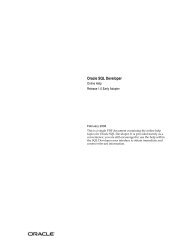
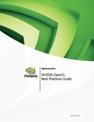
26 CHAPTER 2: OPTIMIZING BANDWIDTHAggregated LinksAggregated links are connections that allow devices to communicateusing up to four member links in parallel. Aggregated links are supportedon the 10/100/1000BASE-T ports and GBIC or SFP ports. These parallellinks provide two benefits:■■They can potentially double, triple or quadruple the bandwidth of aconnection.They can provide redundancy — if one link is broken, the traffic loadcan be shared amongst the remaining link(s).Figure 1 shows two <strong>Switch</strong>es connected using an aggregated linkcontaining two member links. If all ports on both <strong>Switch</strong> units areconfigured as 1000BASE-T and they are operating in full duplex, thepotential maximum bandwidth of the connection is 2 Gbps.Figure 1 <strong>Switch</strong> units connected using an aggregated link.<strong>Switch</strong>Aggregated Link<strong>Switch</strong>How 802.3ad LinkAggregationOperatesYour <strong>Switch</strong> supports IEEE 802.3ad standard aggregated links which usesthe Link Aggregation Control Protocol (LACP). LACP provides automatic,point-to-point redundancy between two devices (switch-to-switch orswitch-to-server) that have full duplex connections operating at the samespeed.By default, LACP is disabled on the 10/100/1000BASE-T and GBIC or SFPports. If you enable LACP your <strong>Switch</strong> will detect if there is more than oneconnection to another device and will automatically create an aggregatedlink consisting of those links.If a member link in an aggregated link fails, the traffic using that link isdynamically reassigned to the remaining member links in the aggregatedlink. Figure 2 shows the simplest case: two member links, that is thephysical links, form an aggregated link. In this example, if link 1 fails, thedata flow between X and B is remapped to physical link 2. The
Aggregated Links 27re-mapping occurs as soon as the <strong>Switch</strong> detects that a member link hasfailed — almost instantaneously. As a result, aggregated linkconfigurations are extremely resilient and fault-tolerant.Figure 2 Dynamic Reassignment of Traffic FlowsAPhysical Link 2Y AYZXB1XX BX2Physical Link 1Aggregated LinkBThe key benefits of 802.3ad link aggregation are:■■■■Automatic configuration — network management does not need tobe used to manually aggregate links.Rapid configuration and reconfiguration.Compatibility — non-802.3ad devices can interoperate with a802.3ad enabled devices. However, you will need to manuallyconfigure the aggregated links as LACP will not be able toautomatically detect and form an aggregation.The operation of 802.3ad can be configured and managed vianetwork management.Implementing802.3ad AggregatedLinksLACP can be enabled or disabled on a per port basis. You can implement802.3ad aggregated links in three ways:■ Manual Aggregations — You can manually add and remove ports toand from an aggregated link via Web or CLI commands. However, if aport has LACP enabled, if a more appropriate or correct automaticmembership is detected by LACP, it will override the manualconfiguration.For example, in Figure 3, if a port on <strong>Switch</strong> C is physically connectedto <strong>Switch</strong> B, but you manually configure the port on <strong>Switch</strong> C to be amember of an aggregated link for <strong>Switch</strong> A in error, LACP (if it isenabled) will detect this and place the port in the aggregated link for<strong>Switch</strong> B, thus overriding the manual configuration.
28 CHAPTER 2: OPTIMIZING BANDWIDTHFigure 3 Aggregated — Link ExampleAggregated Link<strong>Switch</strong> A<strong>Switch</strong> C<strong>Switch</strong> BAggregated Link■■LACP Pre-Configured Aggregations — If you need to know whichaggregated link is associated with which device in your network youcan use a LACP pre-configured aggregation. This allows you tomanually configure the MAC address of a particular partner device(called the partner ID) against a specified aggregated link. LACP willthen automatically determine the port membership for thataggregated link.The aggregated link may be manually configured with appropriateconfiguration settings, such as VLAN membership, to match thepartner device.LACP Automatic Aggregations — If LACP detects at least two activeports sharing the same partner device, and if no matchingpre-configured aggregated links exist, LACP will automatically assign afree un-configured aggregated link to form an aggregated link withthe partner device. The aggregated link will inherit its configurationfrom the first port originally detected against the partner device.If you have an existing single port connection between two devices,this automatic behavior allows quick and easy addition of extrabandwidth by simply adding an extra physical link between the units.The Spanning Tree costs for a port running LACP is the cost assigned foran aggregated link running at that speed. As required by the IEEE802.3ad standard, no changes in cost are made according to the numberof member links in the aggregated link.By default LACP is disabled on all 10/100/1000BASE-T and GBIC or SFP<strong>Switch</strong> ports.
30 CHAPTER 2: OPTIMIZING BANDWIDTH■■The member link ports can have different port configurations withinthe same aggregated link, that is, auto-negotiation, port speed, andduplex mode. However, please note the following:■■To be an active participant in an aggregated link the member linkports must operate in full duplex mode. (If a member link port doesnot operate in full duplex mode it can still be a member of anaggregated link but it will never be activated.)If ports of a different speed are aggregated together, the higherspeed links carry the traffic. The lower speed links only carry thetraffic if the higher speed links fail.Member links must retain the same groupings at both ends of anaggregated link. For example, the configuration in Figure 4 will notwork as <strong>Switch</strong> A has one aggregated link defined whose memberlinks are then split between two aggregated links defined on <strong>Switch</strong>esB and C. Note that this illegal configuration could not occur if LACP isenabled.Figure 4 An illegal aggregated link configuration<strong>Switch</strong> AAL 1<strong>Switch</strong> BAL 2<strong>Switch</strong> CAL 3To make this configuration work you need to have two aggregated linksdefined on <strong>Switch</strong> A, one containing the member links for <strong>Switch</strong> B andthe other containing those for <strong>Switch</strong> C.When using an aggregated link, note that:■ To gather statistics about an aggregated link, you must add togetherthe statistics for each port in the aggregated link.■If you wish to disable a single member link of an aggregated link, youmust first physically remove the connection to ensure that you do notlose any traffic, before you disable both ends of the member link
Aggregated Links 31■separately. If you do this, the traffic destined for that link is distributedto the other links in the aggregated link.If you do not remove the connection and only disable one end of themember link port, traffic is still forwarded to that port by theaggregated link port at the other end. This means that a significantamount of traffic may be lost.Before removing all member links from an aggregated link, you mustdisable all the aggregated link member ports or disconnect all thelinks, except one — if you do not, a loop may be created.Traffic Distribution and Link Failure on Aggregated LinksTo maximize throughput, all traffic is distributed across the individual linksthat make up an aggregated link. Therefore, when a packet is madeavailable for transmission down an aggregated link, a hardware-basedtraffic distribution mechanism determines which particular port in the linkshould be used; this mechanism uses the MAC address. The traffic isdistributed among the member links as efficiently as possible.To avoid the potential problem of out-of-sequence packets (or "packetre-ordering"), the <strong>Switch</strong> ensures that all the conversations between agiven pair of endstations will pass through the same port in theaggregated link. Single-to-multiple endstation conversations, on theother hand, may still take place over different ports.If the link state on any of the ports in an aggregated link becomesinactive due to link failure, then the <strong>Switch</strong> will automatically redirect theaggregated link traffic to the remaining ports. Aggregated links thereforeprovide built-in resilience for your network.
32 CHAPTER 2: OPTIMIZING BANDWIDTHAggregated LinkExampleThe example shown in Figure 5 illustrates an 4 Gbps aggregated linkbetween two <strong>Switch</strong> units.Figure 5 A 4 Gbps aggregated link between two <strong>Switch</strong> units<strong>Switch</strong> <strong>4200</strong> 28-Port4 Gbps Aggregated Link<strong>Switch</strong> <strong>4200</strong> 28-PortTo set up this configuration:1 Add the 1000BASE-T ports on the upper unit to the aggregated link.2 Add the 1000BASE-T ports on the lower unit to the aggregated link.3 Add the SFP ports on the upper unit to the aggregated link.4 Add the SFP ports on the lower unit to the aggregated link.5 Connect the 1000BASE-T port marked ‘Up’ on the upper <strong>Switch</strong> to the1000BASE-T port marked ‘Up’ on the lower <strong>Switch</strong>.6 Connect the 1000BASE-T port marked ‘Down’ on the upper <strong>Switch</strong> tothe 1000BASE-T port marked ‘Down’ on the lower <strong>Switch</strong>.7 Connect the SFP port marked ‘27’ on the upper <strong>Switch</strong> to the SFP portmarked ‘27’ on the lower <strong>Switch</strong>.8 Connect the SFP port marked ‘28’ on the upper <strong>Switch</strong> to the SFP portmarked ‘28’ on the lower <strong>Switch</strong>.
3USING MULTICAST FILTERINGMulticast filtering improves the performance of networks that carrymulticast traffic.This chapter explains multicasts, multicast filtering, and how multicastfiltering can be implemented on your <strong>Switch</strong>. It covers the followingtopics:■■■What is an IP Multicast?Multicast FilteringIGMP Multicast FilteringFor detailed descriptions of the web interface operations and thecommand line interface (CLI) commands that you require to manage the<strong>Switch</strong> please refer to the Management Interface Reference <strong>Guide</strong>supplied in HTML format on the CD-ROM that accompanies your <strong>Switch</strong>.What is an IPMulticast?A multicast is a packet that is intended for “one-to-many” and “manyto-many”communication. Users explicitly request to participate in thecommunication by joining an endstation to a specific multicast group. Ifthe network is set up correctly, a multicast can only be sent to anendstation or a subset of endstations in a LAN, or VLAN, that belong tothe relevant multicast group.Multicast group members can be distributed across multiplesubnetworks; thus, multicast transmissions can occur within a campusLAN or over a WAN. In addition, networks that support IP multicast sendonly one copy of the desired information across the network until thedelivery path that reaches group members diverges. It is only at thesepoints that multicast packets are replicated and forwarded, which makesefficient use of network bandwidth.
34 CHAPTER 3: USING MULTICAST FILTERINGA multicast packet is identified by the presence of a multicast groupaddress in the destination address field of the packet’s IP header.Benefits of MulticastThe benefits of using IP multicast are that it:■■■■Enables the simultaneous delivery of information to many receivers inthe most efficient, logical way.Reduces the load on the source (for example, a server) because it doesnot have to produce multiple copies of the same data.Makes efficient use of network bandwidth and scales well as thenumber of participants or collaborators expands.Works with other IP protocols and services, such as Quality of Service(QoS).There are situations where a multicast approach is more logical andefficient than a unicast approach. Application examples include distancelearning, transmitting stock quotes to brokers, and collaborativecomputing.A typical use of multicasts is in video-conferencing, where high volumesof traffic need to be sent to several endstations simultaneously, but wherebroadcasting that traffic to all endstations would seriously reducenetwork performance.Multicast FilteringMulticast filtering is the process that ensures that endstations only receivemulticast traffic if they register to join specific multicast groups. Withmulticast filtering, network devices only forward multicast traffic to theports that are connected to registered endstations.Figure 6 shows how a network behaves without multicast filtering andwith multicast filtering.
Multicast Filtering 35Figure 6 The effect of multicast filteringMulticast Filteringand Your <strong>Switch</strong>Your <strong>Switch</strong> provides automatic multicast filtering support using IGMP(Internet Group Management Protocol) Snooping. It also supports IGMPquery mode.Snooping ModeSnooping Mode allows your <strong>Switch</strong> to forward multicast packets only tothe appropriate ports. The <strong>Switch</strong> “snoops” on exchanges betweenendstations and an IGMP device, typically a router, to find out the portsthat wish to join a multicast group and then sets its filters accordinglyQuery ModeQuery mode allows the <strong>Switch</strong> to function as the Querier if it has thelowest IP address in the subnetwork to which it belongs.IGMP querying is disabled by default on the <strong>Switch</strong> <strong>4200</strong> <strong>Family</strong>. Thishelps prevent interoperability issues with core products that may notfollow the lowest IP address election method.You can enable or disable IGMP query mode for all <strong>Switch</strong> units in thestack using the queryMode command on the command line interfaceIGMP menu.You would enable query mode if you wish to run multicast sessions in anetwork that does not contain any IGMP routers (or queriers). This
36 CHAPTER 3: USING MULTICAST FILTERINGcommand will configure the <strong>Switch</strong> <strong>4200</strong> Series to automaticallynegotiate with compatible devices on VLAN 1 to become the querier.The <strong>Switch</strong> <strong>4200</strong> <strong>Family</strong> is compatible with any device that conforms tothe IGMP v2 protocol.IGMP MulticastFilteringIGMP is the system that all IP-supporting network devices use to registerendstations with multicast groups. It can be used on all LANs and VLANsthat contain a multicast capable IP router and on other network devicesthat support IP.IGMP multicast filtering works as follows:1 The IP router (or querier) periodically sends query packets to all theendstations in the LANs or VLANs that are connected to it.If your network has more than one IP router, then the one with thelowest IP address becomes the querier. The <strong>Switch</strong> can be the IGMPquerier and will become so if its own IP address is lower than that of anyother IGMP queriers connected to the LAN or VLAN. However, as the<strong>Switch</strong> only has an IP address on its default VLAN, the <strong>Switch</strong> will onlyever query on the default VLAN (VLAN1). Therefore, if there are no otherqueriers on other VLANs, the IP multicast traffic will not be forwarded onthem.2 When an IP endstation receives a query packet, it sends a report packetback that identifies the multicast group that the endstation would like tojoin.3 When the report packet arrives at a port on a <strong>Switch</strong> with IGMP multicastlearning enabled, the <strong>Switch</strong> learns that the port is to forward traffic forthe multicast group and then forwards the packet to the router.4 When the router receives the report packet, it registers that the LAN orVLAN requires traffic for the multicast groups.5 When the router forwards traffic for the multicast group to the LAN orVLAN, the <strong>Switch</strong> units only forward the traffic to ports that received areport packet.Enabling IGMP Multicast LearningYou can enable or disable multicast learning and IGMP querying using thesnoopMode command on the CLI or the web interface. For moreinformation about enabling IGMP multicast learning, please refer to the
IGMP Multicast Filtering 37Management Interface Reference <strong>Guide</strong> supplied on your <strong>Switch</strong>CD-ROM.If IGMP multicast learning is not enabled then IP multicast traffic is alwaysforwarded, that is, it floods the network.For information about configuring IGMP functionality on an endstation,refer to the user documentation supplied with your endstation or theendstation’s Network Interface Card (NIC).
38 CHAPTER 3: USING MULTICAST FILTERING
4USING RESILIENCE FEATURESSetting up resilience on your network helps protect critical links againstfailure, protects against network loops, and reduces network downtimeto a minimum.This chapter explains the features supported by the <strong>Switch</strong> that provideresilience for your network. It covers the following topics:■■Spanning Tree Protocol (STP)Rapid Spanning Tree Protocol (RSTP) — an enhanced version of theSTP feature.For detailed descriptions of the web interface operations and thecommand line interface (CLI) commands that you require to manage the<strong>Switch</strong> please refer to the Management Interface Reference <strong>Guide</strong>supplied in HTML format on the CD-ROM that accompanies your <strong>Switch</strong>.Spanning TreeProtocol (STP)The Spanning Tree Protocol (STP) makes your network more resilient tolink failure and also provides a protection from loops — one of the majorcauses of broadcast storms. STP is enabled by default on your <strong>Switch</strong>.To be fully effective, STP must be enabled on all <strong>Switch</strong>es in yournetwork.RSTP provides the same functionality as STP. For details on how the twosystems differ, see “How RSTP Differs to STP” on page 45.The following sections explain more about STP and the protocol featuressupported by your <strong>Switch</strong>. They cover the following topics:■■■What is STP?How STP WorksUsing STP on a Network with Multiple VLANs
40 CHAPTER 4: USING RESILIENCE FEATURESThe protocol is a part of the IEEE 802.1D bridge specification. To explainSTP more effectively, your <strong>Switch</strong> will be referred to as a bridge.Rapid Spanning TreeProtocol (RSTP)The Rapid Spanning Tree (RSTP) is an enhanced Spanning Tree feature.RSTP implements the Spanning Tree Algorithm and Protocol, as defined inthe IEEE 802.1w standard. RSTP is enabled by default.3Com recommends that you use the Rapid Spanning Tree Protocolfeature (enabled by default) to provide optimum performance for yournetwork and ease of use.Some of the benefits of RSTP are:■■■■Faster determination of the Active Spanning Tree topology throughouta bridged network.Support for bridges with more than 256 ports.Support for Fast-Forwarding configuration of edge ports provided bythe 'Fast Start' feature. Fast Start allows a port that is connected to anendstation to begin forwarding traffic after only four seconds; this“Auto” setting is default for front panel ports. During these fourseconds RSTP (or STP) will detect any misconfiguration that may causea temporary loop and react accordingly.If you have Fast Start disabled on a port, the <strong>Switch</strong> will wait for 30seconds before RSTP (or STP) lets the port forward traffic. If you setFast Start to “Enable” mode, ports enter the forwarding modeimmediately after becoming active. This mode should be used forports connected to edge devices in an AppleTalk network.Easy deployment throughout a legacy network, through backwardcompatibility:■■it will default to sending 802.1D style BPDU's on a port if it receivespackets of this format.it is possible for some ports on a <strong>Switch</strong> to operate in RSTP(802.1w) mode, and other ports, for example those connected to alegacy <strong>Switch</strong>, to operate in STP (802.1D) mode.■ you have an option to force your <strong>Switch</strong> to use the legacy 802.1Dversion of Spanning Tree, if required.
What is STP? 41What is STP?STP is a bridge-based system that allows you to implement parallel pathsfor network traffic and uses a loop-detection process to:■■Find and disable the less efficient paths (that is, the paths that have alower bandwidth).Enable one of the less efficient paths if the most efficient path fails.RSTP provides the same functionality as STP. For details on how the twosystems differ, see “How RSTP Differs to STP” on page 45.As an example, Figure 7 shows a network containing three LAN segmentsseparated by three bridges. With this configuration, each segment cancommunicate with the others using two paths. Without STP enabled, thisconfiguration creates loops that cause the network to overload.Figure 7 A network configuration that creates loopsFigure 8 shows the result of enabling STP on the bridges in theconfiguration. STP detects the duplicate paths and prevents, or blocks,one of them from forwarding traffic, so this configuration will worksatisfactorily. STP has determined that traffic from LAN segment 2 to LANsegment 1 can only flow through Bridges C and A, because, for example,this path has a greater bandwidth and is therefore more efficient.
42 CHAPTER 4: USING RESILIENCE FEATURESFigure 8 Traffic flowing through Bridges C and AIf a link failure is detected, as shown in Figure 9, the STP processreconfigures the network so that traffic from LAN segment 2 flowsthrough Bridge B.Figure 9 Traffic flowing through Bridge BSTP determines which is the most efficient path between each bridgedsegment and a specifically assigned reference point on the network. Oncethe most efficient path has been determined, all other paths are blocked.Therefore, in Figure 7, Figure 8, and Figure 9, STP initially determined thatthe path through Bridge C was the most efficient, and so blocked thepath through Bridge B. After the failure of Bridge C, STP re-evaluated thesituation and opened the path through Bridge B.
How STP Works 43How STP WorksSTP RequirementsWhen enabled, STP determines the most appropriate path for trafficthrough a network. It does this as outlined in the sections below.Before it can configure the network, the STP system requires:■■■Communication between all the bridges. This communication iscarried out using Bridge Protocol Data Units (BPDUs), which aretransmitted in packets with a known multicast address.Each bridge to have a Bridge Identifier. This specifies which bridge actsas the central reference point, or Root Bridge, for the STP system —the lower the Bridge Identifier, the more likely the bridge is to becomethe Root Bridge. The Bridge Identifier is calculated using the MACaddress of the bridge and a priority defined for the bridge. The defaultpriority of your <strong>Switch</strong> is 32768.Each port to have a cost. This specifies the efficiency of each link,usually determined by the bandwidth of the link — the higher thecost, the less efficient the link. Table 3 shows the default port costs fora <strong>Switch</strong>.Table 3 Default port costsPort Speed Link Type10 Mbps Half DuplexFull DuplexAggregated Link100 Mbps Half DuplexFull DuplexAggregated Link1000 Mbps Full DuplexAggregated LinkPath Cost802.1D-1998100959019181543Path Cost802.1w2,000,0001,999,9991,000,000 *200,000199,999100,000*20,00010,000** This path cost is correct where there are two ports in an aggregated link. However, if there aremore ports in the aggregated link, the path cost will be proportionately lower. For example, ifthere are four ports in the aggregated link, the 802.1w path costs will be: 500,000 for10 Mbps, 50,000 for 100 Mbps, and 5,000 for 1000 Mbps. The 802.1D-1998 path cost valuesare not affected by the number of ports in an aggregated link.STP CalculationThe first stage in the STP process is the calculation stage. During thisstage, each bridge on the network transmits BPDUs that allow the systemto work out:
44 CHAPTER 4: USING RESILIENCE FEATURES■■■■The identity of the bridge that is to be the Root Bridge. The RootBridge is the central reference point from which the network isconfigured.The Root Path Costs for each bridge — that is, the cost of the pathsfrom each bridge to the Root Bridge.The identity of the port on each bridge that is to be the Root Port.The Root Port is the one that is connected to the Root Bridge usingthe most efficient path, that is, the one that has the lowest RootPath Cost. Note that the Root Bridge does not have a Root Port.The identity of the bridge that is to be the Designated Bridge ofeach LAN segment. The Designated Bridge is the one that has thelowest Root Path Cost from that segment. Note that if severalbridges have the same Root Path Cost, the one with the lowestBridge Identifier becomes the Designated Bridge.All traffic destined to pass in the direction of the Root Bridge flowsthrough the Designated Bridge. The port on this bridge that connectsto the segment is called the Designated Bridge Port.STP ConfigurationSTP ReconfigurationAfter all the bridges on the network have agreed on the identity of theRoot Bridge, and have established the other relevant parameters, eachbridge is configured to forward traffic only between its Root Port and theDesignated Bridge Ports for the respective network segments. All otherports are blocked, which means that they are prevented from receiving orforwarding traffic.Once the network topology is stable, all the bridges listen for Hello BPDUstransmitted from the Root Bridge at regular intervals. If a bridge does notreceive a Hello BPDU after a certain interval (the Max Age time), thebridge assumes that the Root Bridge, or a link between itself and theRoot Bridge, has gone down. The bridge then reconfigures the networkto cater for the change. If you have configured an SNMP trap destination,when the topology of your network changes, the first bridge to detectthe change sends out an SNMP trap.CAUTION: Network loops can occur if aggregated links are manuallyconfigured incorrectly, that is, the physical connections do not match theassignment of ports to an aggregated link. RSTP and STP may not detectthese loops. So that RSTP and STP can detect all network loops you mustensure that all aggregated links are configured correctly.
How STP Works 45How RSTP Differs toSTPRSTP works in a similar way to STP, but it includes additional informationin the BPDUs. This information allows each bridge to confirm that it hastaken action to prevent loops from forming when it wants to enable alink to a neighbouring bridge. This allows adjacent bridges connected viapoint-to-point links to enable a link without having to wait to ensure allother bridges in the network have had time to react to the change.So the main benefit of RSTP is that the configuration decision is madelocally rather than network-wide which is why RSTP can carry outautomatic configuration and restore a link faster than STP.STP ExampleFigure 10 shows a LAN that has STP enabled. The LAN has threesegments, and each segment is connected using two possible links.Figure 10 Port costs in a network■Bridge A has the lowest Bridge Identifier in the network, and hastherefore been selected as the Root Bridge.
46 CHAPTER 4: USING RESILIENCE FEATURES■■Because Bridge A is the Root Bridge, it is also the Designated Bridgefor LAN segment 1. Port 1 on Bridge A is therefore selected as theDesignated Bridge Port for LAN Segment 1.Port 1 of Bridges B, C, X and Y have been defined as Root Portsbecause they are the nearest to the Root Bridge and therefore havethe most efficient path.■ Bridges B and X offer the same Root Path Cost for LAN segment 2,however, Bridge B has been selected as the Designated Bridge for thesegment because it has a lower Bridge Identifier. Port 2 on Bridge B istherefore selected as the Designated Bridge Port for LAN Segment 2.■Bridge C has been selected as the Designated Bridge for LAN segment3, because it offers the lowest Root Path Cost for LAN Segment 3:■the route through Bridges C and B costs 200 (C to B=100, B toA=100)■ the route through Bridges Y and B costs 300 (Y to B=200, B toA=100).Port 2 on Bridge C is therefore selected as the Designated Bridge Portfor LAN Segment 3.STP Configurations Figure 11 shows three possible STP configurations using SuperStack 3<strong>Switch</strong> units.■■■Configuration 1 — Redundancy for Backbone LinkIn this configuration, the <strong>Switch</strong>es both have STP enabled and areconnected by two links. STP discovers a duplicate path and blocks oneof the links. If the enabled link breaks, the disabled link becomesre-enabled, therefore maintaining connectivity.Configuration 2 — Redundancy through Meshed BackboneIn this configuration, four <strong>Switch</strong> units are connected in a way thatcreates multiple paths between each one. STP discovers the duplicatepaths and blocks two of the links. If an enabled link breaks, one of thedisabled links becomes re-enabled, therefore maintaining connectivity.Configuration 3 — Redundancy for Cabling ErrorIn this configuration, a <strong>Switch</strong> has STP enabled and is accidentallyconnected to a hub using two links. STP discovers a duplicate pathand blocks one of the links, therefore avoiding a loop.
Figure 11 STP configurationsHow STP Works 47
48 CHAPTER 4: USING RESILIENCE FEATURESUsing STP on aNetwork withMultiple VLANsThe IEEE 802.1D standard does not take into account VLANs when itcalculates STP information — the calculations are only performed on thebasis of physical connections. For this reason, some networkconfigurations can result in VLANs being subdivided into a number ofisolated sections by the STP system. Therefore, you must ensure that anyVLAN configuration on your network takes into account the expected STPtopology and alternative topologies that may result from link failures.For example, Figure 12 shows a network containing VLANs 1 and 2. Theyare connected using the 802.1Q-tagged link between <strong>Switch</strong> B and<strong>Switch</strong> C. By default, this link has a path cost of 100 and is automaticallyblocked because the other <strong>Switch</strong>-to-<strong>Switch</strong> connections have a path costof 36 (18+18). This means that both VLANs are now subdivided — VLAN1 on <strong>Switch</strong> units A and B cannot communicate with VLAN 1 on <strong>Switch</strong>C, and VLAN 2 on <strong>Switch</strong> units A and C cannot communicate withVLAN 2 on <strong>Switch</strong> B.Figure 12 Configuration that separates VLANsTo avoid any VLAN subdivision, it is recommended that all inter-<strong>Switch</strong>connections are made members of all available 802.1Q VLANs to ensureconnectivity at all times. For example, the connections between <strong>Switch</strong>esA and B, and between <strong>Switch</strong>es A and C should be 802.1Q tagged andcarrying VLANs 1 and 2 to ensure connectivity.For more information about VLAN Tagging, see Chapter 8 “Setting UpVirtual LANs”.
5USING THE SWITCH DATABASEWhat is the <strong>Switch</strong>Database?The <strong>Switch</strong> Database is used by the <strong>Switch</strong> to determine where a packetshould be forwarded to, and which port should transmit the packet if it isto be forwarded.The database contains a list of entries — each entry contains three items:■■■MAC (Ethernet) address information of the endstation that sendspackets to the <strong>Switch</strong>.Port identifier, that is the port attached to the endstation that issending the packet.VLAN ID of the VLAN to which the endstation belongs.For details of the number of addresses supported by your <strong>Switch</strong>database, please refer to Chapter 1 of the Getting Started <strong>Guide</strong> thataccompanies your <strong>Switch</strong>.For detailed descriptions of the web interface operations and thecommand line interface (CLI) commands that you require to manage the<strong>Switch</strong> please refer to the Management Interface Reference <strong>Guide</strong>supplied in HTML format on the CD-ROM that accompanies your <strong>Switch</strong>.How <strong>Switch</strong>Database EntriesGet AddedEntries are added to the <strong>Switch</strong> Database in one of two ways:■■The <strong>Switch</strong> can learn entries. The <strong>Switch</strong> updates its database with thesource MAC address of the endstation that sent the packet, the VLANID, and the port identifier on which the packet is received.You can enter and update entries using the bridge addressDatabaseCLI command, the Bridge > Address Database Web Interfaceoperation, or an SNMP Network Manager, for example 3ComNetwork Supervisor.
50 CHAPTER 5: USING THE SWITCH DATABASE<strong>Switch</strong> DatabaseEntry StatesDatabases entries can have three states:■■■Learned — The <strong>Switch</strong> has placed the entry into the <strong>Switch</strong> Databasewhen a packet was received from an endstation. Note that:■■Learned entries are removed (aged out) from the <strong>Switch</strong> Databaseif the <strong>Switch</strong> does not receive further packets from that endstationwithin a certain period of time (the aging time). This prevents the<strong>Switch</strong> Database from becoming full with obsolete entries byensuring that when an endstation is removed from the network, itsentry is also removed from the database.Learned entries are removed from the <strong>Switch</strong> Database if the<strong>Switch</strong> is reset or powered-down.Non-aging learned — If the aging time is set to 0 seconds, all learnedentries in the <strong>Switch</strong> Database become non-aging learned entries. Thismeans that they are not aged out, but they are still removed from thedatabase if the <strong>Switch</strong> is reset or powered-down.Permanent — The entry has been placed into the <strong>Switch</strong> Databaseusing the management interface. Permanent entries are not removedfrom the <strong>Switch</strong> Database unless they are removed using the bridgeaddressDatabase remove CLI command or the <strong>Switch</strong> is initialized.
6USING TRAFFIC PRIORITIZATIONUsing the traffic prioritization capabilities of your <strong>Switch</strong> allows yournetwork traffic to be prioritized to ensure that high priority data istransmitted with minimum delay.For a list of the features supported by your <strong>Switch</strong>, please refer to theManagement Quick Reference <strong>Guide</strong> supplied in PDF format on theCD-ROM that accompanies your <strong>Switch</strong>.For detailed descriptions of the web interface operations and thecommand line interface (CLI) commands that you require to manage the<strong>Switch</strong> please refer to the Management Interface Reference <strong>Guide</strong>supplied in HTML format on the CD-ROM that accompanies your <strong>Switch</strong>.The SuperStack 3 <strong>Switch</strong> <strong>4200</strong> <strong>Family</strong> has two traffic queues per portgiving it a basic capability to prioritize traffic. For more granularprioritization and an enhanced Quality of Service support, other productsare available in the 3Com range of stackable <strong>Switch</strong>es.What is TrafficPrioritization?Traffic prioritization allows high priority data, such as time-sensitive andsystem-critical data to be transferred smoothly and with minimal delayover a network.Traffic prioritization is most useful for critical applications that require ahigh level of service from the network. These could include:■Converged network applications — Used by organizations with aconverged network, that is, a network that uses the sameinfrastructure for voice and video data and traditional data.Organizations that require high quality voice and video datatransmission at all times can ensure this by maximising bandwidth andproviding low latency.
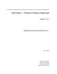
52 CHAPTER 6: USING TRAFFIC PRIORITIZATION■■■Resource planning applications — Used by organizations thatrequire predictable and reliable access to enterprise resource planningapplications such as SAP.Financial applications — Used by Accounts departments that needimmediate access to large files and spreadsheets.CAD/CAM design applications — Used by design departments thatneed priority connections to server farms and other devices fortransferring large files.How TrafficPrioritization WorksTraffic prioritization ensures that high priority data is forwarded throughthe <strong>Switch</strong> without being delayed by lower priority data. Trafficprioritization uses the two traffic queues that are present in the hardwareof the <strong>Switch</strong> to ensure that high priority traffic is forwarded on adifferent queue from lower priority traffic. High priority traffic is givenpreference over low priority traffic to ensure that the most critical trafficgets the highest level of service.The <strong>Switch</strong> employs two methods of classifying traffic for prioritization.Traffic classification is the means of identifying which applicationgenerated the traffic, so that a service level can be applied to it.The two supported methods for classifying traffic are:■■802.1D (classification is done at layer 2 of the OSI model).DiffServ code point (classification is done at layer 3 of the OSI model).802.1D trafficclassificationAt layer 2, a traffic service class is defined in 802.1Q frame, which is ableto carry VLAN identification and user priority information. Theinformation is carried in a header field immediately following thedestination MAC address, and Source MAC address.802.1D Priority LevelsThe traffic prioritization feature supported by the <strong>Switch</strong> at layer 2 iscompatible with the relevant sections of the IEEE 802.1D/D17 standard(incorporating IEEE 802.1p). Once a packet has been classified, the levelof service relevant to that type of packet is applied to it.The 802.1D standard specifies eight distinct levels of priority (0 to 7),each of which relates to a particular type of traffic. The priority levels andtheir traffic types are shown in Figure 13 in order of increasing priority.
How Traffic Prioritization Works 53You cannot alter the mapping of priority levels 0 - 7 to the traffic queues.These priority levels are fixed to the traffic queues as shown in Figure 13.Figure 13 IEEE 802.1D traffic types802.1pService levelsClassificationBest effortBackgroundSpare012Strict PriorityQueue SchedulingLow Priority QueueIngress Port802.1DBusiness Critical 3Multimedia 4Egress PortVideoVoice56High Priority QueueNetwork Control 7Figure 13 illustrates IEEE 802.1D traffic types as well as associated prioritylevels and how they are mapped to the two supported traffic queues.The 802.1D service level of the packet is not altered by the <strong>Switch</strong> <strong>4200</strong>Series.DiffServ trafficclassificationDiffServ is an alternative method of classifying traffic so that differentlevels of service can be applied to it on a network. DiffServ is a layer 3function; and the service to be applied is contained within the DSCP field,which is in the IP header of a packet.
54 CHAPTER 6: USING TRAFFIC PRIORITIZATIONFigure 14 DSCP Service Level MappingDSCPService levelsClassificationService Level 2Best EffortService Level 3Business CriticalStrict PriorityQueue SchedulingLow Priority QueueIngress PortDSCPService Level 4Video ApplicationsService Level 5Voice ApplicationsAllEgress PortsService Level 6Internetwork ControlService Level 7Network ControlHigh Priority QueueFigure 14 illustrates how DiffServ code point (DSCP) service levels aremapped to the two Traffic Queues.The DSCP service level of the packet is not altered by the <strong>Switch</strong> <strong>4200</strong><strong>Family</strong>.Traffic Prioritizationand your <strong>Switch</strong>The traffic should be marked as it enters the network; the marking can beachieved in two ways:■■The original device can apply the DSCP or 802.1p markings to thepacket before transmission.The edge port on the <strong>Switch</strong> connecting the originating device canclassify and mark or re-mark the packets before sending them to thenetwork. This is not done by the <strong>Switch</strong> <strong>4200</strong> <strong>Family</strong>, an intermediatedevice in the network is required to do this.Received packets in the <strong>Switch</strong> <strong>4200</strong> <strong>Family</strong> are checked for DSCPclassification and IEEE 802.1D priority. The <strong>Switch</strong> <strong>4200</strong> <strong>Family</strong> does notset or modify priority levels within the packet.The transmitting endstation sets the priority of each packet. When thepacket is received, the <strong>Switch</strong> places the packet into the appropriatequeue, depending on its priority level, for onward transmission across thenetwork. The <strong>Switch</strong> determines which queue to service next through itsStrict Priority queuing mechanism. This method services both trafficqueues, giving priority to the high priority queue.
Traffic Prioritization and your <strong>Switch</strong> 55How traffic is processed to provide Quality of ServiceA received packet at the ingress port is checked for its DSCP and IEEE802.1D attributes to determine the level of service that the packet shouldreceive.802.1D packets are categorized into the 8 traffic classes defined by IEEE802.1D; the higher the class the higher the priority given the packet ontransmission.DSCP packets are categorized into the six service levels as shown inFigure 14 and mapped to the appropriate queue.The priority defined in the service level directs the packet to theappropriate egress queue. When a packet comes in with both 802.1Dand DSCP priority markings, the higher of the priorities will be used.Received packets in the <strong>Switch</strong> <strong>4200</strong> <strong>Family</strong> are only checked for DSCPand 802.1D attributes. No other attributes are supported.Traffic queues are preset on a per-unit basis on the <strong>Switch</strong> <strong>4200</strong> <strong>Family</strong>.Configuring traffic prioritization for QoS on a <strong>4200</strong> <strong>Family</strong>QoS can be configured on your <strong>Switch</strong> using the 3Com NetworkSupervisor or via the Command Line Interface (CLI).You can also configure QoS via the command line interface (CLI). For adetailed description of the commands that you require, refer to theManagement Interface Reference <strong>Guide</strong> supplied in HTML format on theCD-ROM that accompanies your <strong>Switch</strong>.Configure Quality of service in the <strong>Switch</strong> <strong>4200</strong> <strong>Family</strong> in the followingway:1 Apply Traffic classification First identify the types of traffic requiringspecial treatment. These types are defined in the QoS feature through thecreation of classifiers. The <strong>Switch</strong> <strong>4200</strong> <strong>Family</strong> supports two types ofpacket attributes on which to classify incoming traffic, DifferentiatedServices Code Point (DSCP) and IEEE 802.1D.2 Identify Service Levels You must then identify the level of service eachclassifier should receive. Note that DSCP service levels will be setsomewhere else in the network and not in the <strong>Switch</strong> <strong>4200</strong> <strong>Family</strong>. Notealso that 802.1D service levels are fixed and cannot be altered.
56 CHAPTER 6: USING TRAFFIC PRIORITIZATION3 Create Profiles The next step is to create a profile, which associatesclassifiers with service levels.4 Apply QoS profile After a QoS profile has been created, it can beassigned to the Port(s). When the profile is assigned to the port(s), theQoS configuration defined in the profile will immediately become active.Head of Line Blocking (HOL)You can adjust the Head of Line Blocking settings for Fast Ethernet portsto one of the following:■■■QoS — This is the default setting. Using this setting, the <strong>Switch</strong> uses amaximum of 12 packets of egress buffering per port (potentially 18kilobytes) for normal priority traffic. This gives the flexibility to ensurethat high priority traffic can be provided with sufficient extrabuffering. Ingress flow control is not normally required with thissetting. Data protocols operating window sizes greater that 18kilobytes will not work efficiently with this setting.Data — This setting increases the maximum egress buffer per port to32 kilobytes or 27 packets. This setting is suitable if data applicationsrequire a window size of up to 32 kilobytes. Under thesecircumstances, high priority traffic may not always be able to accesssufficient <strong>Switch</strong> buffers to guarantee the expected QoS.Advanced — You should only use this setting if you are anexperienced network administrator. It allows you to set HOL to suitcertain specialist applications. It has two modes:■■Disable — This mode disables HOL completely. All egress andingress buffers will be used on demand and QoS settings will belargely ineffective in buffer-overload situations. When ingressbuffers are exhausted, flow control will operate.Enable HOL with specific HOL values — This allows you to set avalue between 10 and 50 kilobytes of egress buffering.
7STATUS MONITORING ANDSTATISTICSThis chapter contains details of the features that assist you with statusmonitoring and statistics.For detailed descriptions of the web interface operations and thecommand line interface (CLI) commands that you require to manage the<strong>Switch</strong> please refer to the Management Interface Reference <strong>Guide</strong>supplied in HTML format on the CD-ROM that accompanies your <strong>Switch</strong>.RMONUsing the RMON capabilities of a <strong>Switch</strong> allows you to improve yournetwork efficiency and reduce the load on your network.This section explains more about RMON. It covers the following topics:■■■What is RMON?Benefits of RMONRMON and the <strong>Switch</strong>What is RMON?RMON is a system defined by the IETF (Internet Engineering Task Force)that allows you to monitor the traffic of LANs or VLANs.RMON is an integrated part of the <strong>Switch</strong> software agent and continuallycollects statistics about a LAN segment or VLAN, and transfers theinformation to a management workstation on request or when apre-defined threshold is crossed. The workstation does not have to be onthe same network as the <strong>Switch</strong> and can manage the <strong>Switch</strong> by in-bandor out-of-band connections.The RMON GroupsThe IETF define groups of Ethernet RMON statistics. This section describesthe four groups supported by the <strong>Switch</strong> <strong>4200</strong> <strong>Family</strong>, and details howyou can use them.
58 CHAPTER 7: STATUS MONITORING AND STATISTICSStatisticsThe Statistics group provides traffic and error statistics showing packets,bytes, broadcasts, multicasts and errors on a LAN segment.Information from the Statistics group is used to detect changes in trafficand error patterns in critical areas of your network.HistoryThe History group provides historical views of network performance bytaking periodic samples of the counters supplied by the Statistics group.The group is useful for analyzing the traffic patterns and trends on a LANsegment, and for establishing the normal operating parameters of yournetwork.AlarmsThe Alarms group provides a mechanism for setting thresholds andsampling intervals to generate events on any RMON variable.Alarms are used to inform you of network performance problems andthey can trigger automated responses through the Events group.EventsThe Events group provides you with the ability to create entries in anevent log and send SNMP traps to the management workstation. Eventsare the action that can result from an RMON alarm. In addition to thestandard five traps required by SNMP (link up, link down, warm start, coldstart, and authentication failure), RMON adds two more: rising thresholdand falling threshold.Effective use of the Events group saves you time; rather than having towatch real-time graphs for important occurrences, you can depend onthe Event group for notification. Through the SNMP traps, events cantrigger other actions, therefore providing a way to automatically respondto certain occurrences.Certain Events can also generate automatic emails. See “EmailNotification of Events” on page 62.
Benefits of RMON 59Benefits of RMONUsing the RMON features of your <strong>Switch</strong> has three main advantages:■■■It improves your efficiencyUsing RMON allows you to remain at one workstation and collectinformation from widely dispersed LAN segments or VLANs. Thismeans that the time taken to reach a problem site, set up equipment,and begin collecting information is largely eliminated.It allows you to manage your network in a more proactivemannerIf configured correctly, RMON can deliver information before problemsoccur. This means that you can take action before they affect users. Inaddition, probes record the behavior of your network, so that you cananalyze the causes of problems.It reduces the load on the network and the managementworkstationTraditional network management involves a management workstationpolling network devices at regular intervals to gather statistics andidentify problems or trends. As network sizes and traffic levels grow,this approach places a strain on the management workstation andalso generates large amounts of traffic.RMON, however, autonomously looks at the network on behalf of themanagement workstation without affecting the characteristics andperformance of the network. RMON reports by exception, whichmeans that it only informs the management workstation when thenetwork has entered an abnormal state.RMON and the<strong>Switch</strong>The RMON support provided by your <strong>Switch</strong> is detailed in Table 4.
60 CHAPTER 7: STATUS MONITORING AND STATISTICSTable 4 RMON support supplied by the <strong>Switch</strong>RMON groupStatisticsHistoryAlarmsEventsSupport supplied by the <strong>Switch</strong>A new or initialized <strong>Switch</strong> has one Statistics session per port.A new or initialized <strong>Switch</strong> has two History sessions per port.These sessions provide the data for the Web interface historydisplays:■ 30 second intervals, 120 historical samples stored■ 2 hour intervals, 96 historical samples storedA new or initialized <strong>Switch</strong> has the following alarm(s) defined foreach port:■ Broadcast bandwidth used■ Percentage of errors over one minuteYou can modify these alarms using an RMON managementapplication, but you cannot create or delete them.You can define up to 200 alarms for the <strong>Switch</strong>.For more information about the alarms setup on the <strong>Switch</strong>, see“Alarm Events” on page 60 and “The Default AlarmSettings” on page 61.A new or initialized <strong>Switch</strong> has Events defined for use with thedefault alarm system. See “The Default Alarm Settings” onpage 61 for more information.When using the RMON features of the <strong>Switch</strong>, note the following:■■After the default sessions are created, they have no special status. Youcan delete or change them as required.The greater the number of RMON sessions, the greater the burden onthe management resources of the <strong>Switch</strong>. If you have many RMONsessions, the forwarding performance of the <strong>Switch</strong> is not affected butyou may experience slow response times from the web interface.Alarm EventsYou can define up to 200 alarms for the <strong>Switch</strong>. The events that you candefine for each alarm and their resulting actions are listed in Table 5.Table 5 Alarm EventsEventNo actionNotify onlyActionSend Trap.
RMON and the <strong>Switch</strong> 61Table 5 Alarm EventsEventNotify and filter portNotify and disable portNotify and enable portDisable portEnable portNotify and unfilter portSystem startedSoftware Upgrade reportActionSend Trap. Block broadcast and multicasttraffic on the port. Recovers with the unfilterport event.Send Trap. Turn port off.Send Trap. Turn port on.Turn port off.Turn port on.Send Trap. Stop blocking broadcast andmulticast traffic on the port.The Default AlarmSettingsA new or initialized <strong>Switch</strong> has the following alarm(s) defined for eachport:■■Broadcast bandwidth usedPercentage of errors over one minuteThe default values and actions for each of these alarms are given inTable 6.Table 6 Values for the default alarm(s)StatisticHigh ThresholdLow ThresholdRecoveryPeriodBroadcastbandwidth usedValue: 20%Action: Notify and filterValue: 10%Action: Notify and unfilter30 secsNumber of errorsover 10 secondsValue: 8 errors per 10secondsValue: 8 errors per 10seconds10 secsAction: Smartauto-sensing will reduceport speedAction: None. (Speed canonly be increased uponlink loss, for example byremoving and replacingthe cable, or by triggeringthe port to performanother auto-negotiationon that link.)
62 CHAPTER 7: STATUS MONITORING AND STATISTICSThe Audit LogThe <strong>Switch</strong> keeps an audit log of all management user sessions, providinga record of a variety of changes, including ones relating to RMON. Thelog can only be read by users at the security access level using an SNMPNetwork Management application.Each entry in the log contains information in the following order:■ Entry number■ Timestamp■ User ID■ Item ID (including qualifier)■ New value of itemThe last 16 operations are stored in the audit log. The oldest records areoverwritten first.Email Notification ofEventsYour <strong>Switch</strong> allows you to receive email notification when certain RMONevents occur. You can receive notification via email, SMS (Short MessageService), or pager, of the event that has occurred.This feature uses an SMTP (Simple Mail Transfer Protocol) email client tosend the notification email. The Short Message Service (SMS) and pagermessages are constrained on message size so they are sent to a differentemail address which creates the message to be displayed and thenforwards it on to the SMS or pager gateway.You can configure the email address to which you wish the notificationsto be sent. However, you cannot change the factory default notificationmessages for event emails.RMON traps continue to be sent, in addition to any email notificationsyou may receive.The events that can generate email notification are:■ Unit powers up.■ Unit in the stack fails.■ Fan in the unit fails.
RMON and the <strong>Switch</strong> 63■■■■■■■■■■■■■A link fails or returns to service — you can select specific links that youwish to receive messages for, for example, a mission-critical link to aserver.A security violation occurs.A resilient link activatesSystem StartedSmart Autosensing ActivatedTemperature CriticalSecure address learnedExecution of intrusion actionAuthentication failurePOST Failed portsPort access authentication failurePort access logonPort access logoff
64 CHAPTER 7: STATUS MONITORING AND STATISTICS
8SETTING UP VIRTUAL LANSSetting up Virtual LANs (VLANs) on your <strong>Switch</strong> reduces the time andeffort required by many network administration tasks, and increases theefficiency of your network.This chapter explains more about the concept of VLANs and explains howthey can be implemented on your <strong>Switch</strong>. It covers the following topics:■■■■What are VLANs?Benefits of VLANsVLANs and Your <strong>Switch</strong>VLAN Configuration ExamplesFor detailed descriptions of the web interface operations and thecommand line interface (CLI) commands that you require to manage the<strong>Switch</strong> please refer to the Management Interface Reference <strong>Guide</strong>supplied in HTML format on the CD-ROM that accompanies your <strong>Switch</strong>.What are VLANs?A VLAN is a flexible group of devices that can be located anywhere in anetwork, but which communicate as if they are on the same physicalsegment. With VLANs, you can segment your network without beingrestricted by physical connections — a limitation of traditional networkdesign. As an example, with VLANs you can segment your networkaccording to:■■■Departmental groups — For example, you can have one VLAN forthe Marketing department, another for the Finance department, andanother for the Development department.Hierarchical groups — For example, you can have one VLAN fordirectors, another for managers, and another for general staff.Usage groups — For example, you can have one VLAN for users ofe-mail, and another for users of multimedia.
66 CHAPTER 8: SETTING UP VIRTUAL LANSFigure 15 A network setup showing three VLANsBenefits of VLANsThe main benefit of VLANs is that they provide a network segmentationsystem that is far more flexible than any traditional network. Using VLANsalso provides you with three other benefits:■■VLANs ease the movement of devices on networksWith traditional networks, network administrators spend much oftheir time dealing with moves and changes. If users move to adifferent subnetwork, the addresses of each endstation must beupdated manually.With a VLAN setup, if an endstation in VLAN Marketing for example ismoved to a port in another part of the network, and retains its originalsubnet membership, you only need to specify that the new port is inVLAN Marketing. You do not need to carry out any re-cabling.VLANs provide extra securityDevices within each VLAN can only communicate with other devices inthe same VLAN. If a device in VLAN Marketing needs to communicatewith devices in VLAN Finance, the traffic must pass through a routingdevice or Layer 3 switch.
VLANs and Your <strong>Switch</strong> 67■VLANs help to control trafficWith traditional networks, congestion can be caused by broadcasttraffic that is directed to all network devices whether they require it ornot. VLANs increase the efficiency of your network because eachVLAN can be set up to contain only those devices that need tocommunicate with each other.VLANs and Your<strong>Switch</strong>Your <strong>Switch</strong> provides support for VLANs using the IEEE 802.1Q standard.This standard allows traffic from multiple VLANs to be carried across onephysical link.The IEEE 802.1Q standard allows each port on your <strong>Switch</strong> to be placedin:■■Any one VLAN defined on the <strong>Switch</strong>.Several VLANs at the same time using 802.1Q tagging.The standard requires that you define the following information abouteach VLAN on your <strong>Switch</strong> before the <strong>Switch</strong> can use it to forward traffic:■■VLAN Name — This is a descriptive name for the VLAN (for example,Marketing or Management).802.1Q VLAN ID — This is used to identify the VLAN if you use802.1Q tagging across your network.The Default VLANA new or initialized <strong>Switch</strong> contains a single VLAN, the Default VLAN.This VLAN has the following definition:■■VLAN Name — Default VLAN802.1Q VLAN ID — 1 (if tagging is required)All the ports are initially placed in this VLAN, and it is the only VLAN thatallows you to access the management software of the <strong>Switch</strong> over thenetwork.CommunicationBetween VLANsIf the devices placed in a VLAN need to communicate to devices in adifferent LAN, each VLAN requires a connection to a router or Layer 3switching device. Communication between VLANs can only take place ifthey are all connected to a routing or Layer 3 switching device.
68 CHAPTER 8: SETTING UP VIRTUAL LANSFigure 16 Two VLANS connected via a routerCreating New VLANsVLANs: Tagged andUntaggedMembershipIf you want to move a port from the Default VLAN to another VLAN, youmust first define information about the new VLAN on your <strong>Switch</strong>.Your <strong>Switch</strong> supports 802.1Q VLAN tagging, a system that allows trafficfor multiple VLANs to be carried on a single physical (backbone) link.When setting up VLANs you need to understand when to use untaggedand tagged membership of VLANs. Quite simply, if a port is in a singleVLAN it can be an untagged member but if the port needs to be amember of multiple VLANs tagged membership must be defined.Typically endstations (for example, clients or servers) will be untaggedmembers of one VLAN, while inter-<strong>Switch</strong> connections will be taggedmembers of all VLANs.The IEEE 802.1Q standard defines how VLANs operate within an openpacket-switched network. An 802.1Q compliant packet carries additionalinformation that allows a switch to determine to which VLAN the portbelongs. If a frame is carrying the additional information, it is known astagged.To carry multiple VLANs across a single physical (backbone) link, eachpacket must be tagged with a VLAN identifier so that the <strong>Switch</strong>es can
VLANs and Your <strong>Switch</strong> 69identify which packets belong in which VLANs. To communicate betweenVLANs a router must be used.Placing a Port in aSingle VLANOnce the information for a new VLAN has been defined, you can place aport in that VLAN.Creating an IEEE 802.1Q Tagged LinkThis method of tagging is defined in the IEEE 802.1Q standard, andallows a link to carry traffic for any of the VLANs defined on your <strong>Switch</strong>.802.1Q tagging can only be used if the devices at both ends of a linksupport IEEE 802.1Q.To create an 802.1Q tagged link:1 Ensure that the device at the other end of the link uses the same 802.1Qtags as your <strong>Switch</strong>, that is, the same VLAN IDs are configured (note thatVLAN IDs are global across the network).2 Place the <strong>Switch</strong> ports in the required VLANs as tagged members.3 Place the port at the other end of the link as a tagged member of thesame VLANs as the port on your <strong>Switch</strong>.
70 CHAPTER 8: SETTING UP VIRTUAL LANSVLANConfigurationExamplesUsing UntaggedConnectionsThis section contains examples of simple VLAN configurations. Itdescribes how to set up your switch to support simple untagged andtagged connections.The simplest VLAN operates in a small network using a single switch. Inthis network there is no requirement to pass traffic for multiple VLANsacross a link. All traffic is handled by the single <strong>Switch</strong> and thereforeuntagged connections can be used.The example shown in Figure 17 illustrates a single <strong>Switch</strong> connected toendstations and servers using untagged connections. Ports 1, 2 and 3 ofthe <strong>Switch</strong> belong to VLAN 1, ports 10, 11 and 12 belong to VLAN 2.VLANs 1 and 2 are completely separate and cannot communicate witheach other. This provides additional security for your network.Figure 17 VLAN configuration example: Using untagged connectionsTo set up the configuration shown in Figure 17:1 Configure the VLANsCreate VLAN 2 on the <strong>Switch</strong>. VLAN 1 is the default VLAN and alreadyexists.
VLAN Configuration Examples 712 Add ports to the VLANsAdd ports 10, 11 and 12 of the <strong>Switch</strong> as untagged members to VLAN 2.Using 802.1Q TaggedConnectionsIn a network where the VLANs are distributed amongst more than one<strong>Switch</strong>, you must use 802.1Q tagged connections so that all VLAN trafficcan be passed along the links between the <strong>Switch</strong>es. 802.1Q tagging canonly be used if the devices at both ends of a link support IEEE 802.1Q.The example shown in Figure 18 illustrates two <strong>Switch</strong> units. Each switchhas endstations and a server in VLAN 1 and VLAN 2. All endstations inVLAN 1 need to be able to connect to the server in VLAN1 which isattached to <strong>Switch</strong> 1 and all endstations in VLAN 2 need to connect tothe server in VLAN2 which is attached to <strong>Switch</strong> 2.Figure 18 VLAN configuration example: 802.1Q tagged connectionsTo set up the configuration shown in Figure 18:1 Configure the VLANs on <strong>Switch</strong> 1Define VLAN 2. VLAN 1 is the default VLAN and already exists.2 Add endstation ports on <strong>Switch</strong> 1 to the VLANsPlace the endstation ports in the appropriate VLANs as untaggedmembers.
72 CHAPTER 8: SETTING UP VIRTUAL LANS3 Add port 12 on <strong>Switch</strong> 1 to the VLANsAdd port 12 on <strong>Switch</strong> 1 as a tagged member of both VLANs 1 and 2 sothat all VLAN traffic is passed over the link to <strong>Switch</strong> 2.4 Configure the VLANs on <strong>Switch</strong> 2Define VLAN 2. VLAN 1 is the default VLAN and already exists.5 Add endstation ports on <strong>Switch</strong> 2 to the VLANsPlace the endstation ports in the appropriate VLANs as untaggedmembers.6 Add port 11 on <strong>Switch</strong> 2 to the VLANsAdd port 11 on <strong>Switch</strong> 2 as a tagged member of both VLANs 1 and 2 sothat all VLAN traffic is passed over the link to <strong>Switch</strong> 1.7 Check the VLAN membership for both switchesThe relevant ports should be listed in the VLAN members summary.8 Connect the switchesConnect port 12 on <strong>Switch</strong> 1 to port 11 on <strong>Switch</strong> 2.The VLANs are now configured and operational and the endstations inboth VLANs can communicate with their relevant servers.
9USING AUTOMATIC IPCONFIGURATIONThis chapter explains more about IP addresses and how the automaticconfiguration option works. It covers the following topics:■■■How Your <strong>Switch</strong> Obtains IP InformationHow Automatic IP Configuration WorksImportant ConsiderationsFor detailed information on setting up your <strong>Switch</strong> for management, seethe Getting Started <strong>Guide</strong> that accompanies your <strong>Switch</strong>.For detailed descriptions of the web interface operations and thecommand line interface (CLI) commands that you require to manage the<strong>Switch</strong> please refer to the Management Interface Reference <strong>Guide</strong>supplied in HTML format on the CD-ROM that accompanies your <strong>Switch</strong>.For background information on IP addressing, see Appendix C “IPAddressing”.
74 CHAPTER 9: USING AUTOMATIC IP CONFIGURATIONHow Your <strong>Switch</strong>Obtains IPInformationYou can use one of the following methods to allocate IP information toyour <strong>Switch</strong> (essential if you wish to manage your <strong>Switch</strong> across thenetwork):■■Automatic IP Configuration (default) — the <strong>Switch</strong> tries toconfigure itself with IP information. It uses the following industrystandard methods to automatically allocate the <strong>Switch</strong> IP information:■■Dynamic Host Configuration Protocol (DHCP)Auto-IP — the <strong>Switch</strong> will configure itself with its default IP address169.254.100.100 if it is operating in a standalone mode, and/or noother <strong>Switch</strong>es on the network have this IP address. If this defaultIP address is already in use on the network then the <strong>Switch</strong> detectsthis and configures itself with an IP address in the range169.254.1.0 to 169.254.254.255.■ Bootstrap Protocol (BOOTP)For ease of use, you do not have to choose between these threeautomatic configuration methods. The <strong>Switch</strong> tries each method in aspecified order as described in “Automatic Process” on page 75.Manual IP Configuration — you can manually input the IPinformation (IP address, subnet mask, and default gateway).If you select an option for no IP configuration the <strong>Switch</strong> will not beaccessible from a remote management workstation on the LAN. Inaddition, the <strong>Switch</strong> will not be able to respond to SNMP requests.How Automatic IPConfigurationWorksWhen your <strong>Switch</strong> is powered up for the first time the IP configurationsetting is set to automatic — this is the default setting.If your <strong>Switch</strong> has been powered up before, whichever of the threeoptions for IP configuration (manual, automatic, none) was lastconfigured is activated when the <strong>Switch</strong> powers up again.You can switch to manual IP configuration at any time using a serial portconnection to set up the IP information. For more information see theGetting Started <strong>Guide</strong> that accompanies your <strong>Switch</strong>.
How Automatic IP Configuration Works 75Automatic ProcessTo detect its IP information using the automatic configuration process,the <strong>Switch</strong> goes through the following sequence of steps:1 The DHCP client that resides in the <strong>Switch</strong> makes up to four attempts tocontact a DHCP server on the network requesting IP information from theserver. The attempts are at 0, 4, 12, 28 second intervals.■ If a DHCP server is on the network and working correctly it respondsto the clients request with an IP address (allocated from a pool ofavailable addresses) and other parameters such as a subnet mask,default gateway, lease time, and any other options configured in theDHCP server.The way a DCHP server responds is dependant on the DHCP serversettings. Therefore the way your DHCP server responds may be differentto the process outlined.■ If the DHCP process fails after 30 seconds on all four attempts, thenthe <strong>Switch</strong> activates its Auto-IP configuration feature.2 The Auto-IP feature starts with an IP address of 169.254.100.100. It usesthe Address Resolution Protocol (ARP) to check to make sure this addressis not already in use on the network. If not, it will allocate this defaultaddress to the <strong>Switch</strong>.If this IP address is already in use, Auto-IP will check once every second forthree seconds for an IP address on the 169.254.x.y subnet (where x =1-254 and y = 0-255) (Auto-IP only uses addresses in the range169.254.1.0 through to 169.254.254.255 as valid addresses.) OnceAuto-IP has ensured that an IP address is not already in use on thenetwork, it assigns it to the <strong>Switch</strong> with a subnet mask of 255.255.0.0and a default gateway of 0.0.0.0.3 While the Auto-IP assigned address is in use:■■The Auto-IP client continues to check every 30 seconds (using ARP) toensure that any other Auto-IP hosts have not mistakenly configuredthemselves using the same Auto-IP address.DHCP and BOOTP requests also continue in the background. Therequests begin 3 minutes after either the Auto-IP address is assigned,or 125 attempts to establish a valid Auto-IP address, whichever occursfirst. The requests proceed with DHCP requests for 1 minute; a 3minute pause; DHCP requests for another minute; a 3 minute pause;BOOTP requests for one minute; a 3 minute pause; then the processrepeats until a DHCP or BOOTP server answers the requests.
76 CHAPTER 9: USING AUTOMATIC IP CONFIGURATIONImportantConsiderationsThis section contains some important points to note when using theautomatic IP configuration feature.The dynamic nature of automatically configured IP information meansthat a <strong>Switch</strong> may change its IP address whilst in use.Event Log Entriesand TrapsAn event log will be generated and an SNMP trap will be sent if any ofthe following changes occur in the IP configuration:■■■■IP address configuration is changed manuallyIP address changes from Auto-IP to DHCP IP configurationDHCP negotiates a change in the IP configuration from Auto-IPBOOTP negotiates a change in the IP configuration
10MAKING YOUR NETWORK SECUREThis chapter explains the security features of the <strong>Switch</strong> and givesexamples of how and why you would use them in your network. It coversthe following topics:■■■■■■Port SecurityWhat is Network Login?What is Rada?Auto VLAN AssignmentWhat is Disconnect Unauthorized Device (DUD)?What is RADIUS?For detailed descriptions of the Web interface operations and theCommand Line Interface (CLI) commands that you require to manage the<strong>Switch</strong> please refer to the Management Interface Reference <strong>Guide</strong>supplied in HTML format on the CD-ROM that accompanies your <strong>Switch</strong>.
78 CHAPTER 10: MAKING YOUR NETWORK SECUREPort SecurityThe <strong>Switch</strong> supports the following port security modes, which you can setfor an individual port or a range of ports:■■■■■■No SecurityPort security is disabled and all network traffic is forwarded throughthe port without any restrictions.Continuous LearningMAC addresses are learned continuously by the port until the numberof authorized addresses specified is reached. When this number isexceeded the first address that was learned by the port is deleted,allowing a new address to be learned.Automatic LearningMAC addresses are learned continuously by the port until the numberof authorized addresses specified is reached. When this number isexceeded the port automatically stops learning addresses andDisconnect Unauthorized Device (DUD) is enabled on the port. Forfurther information see “What is Disconnect Unauthorized Device(DUD)?” on page 85.Learning OffOnly traffic received from an authorized address (either configured bymanagement or learned while the port was prevously operating in the"Automatic Learning" mode) is forwarded. While in this mode theDUD operation is enabled. When a port in this mode has learned themaximum number of authorized addresses configured for the portthen it will transition to the "Learning Off" mode.Network LoginWhen a 802.1X client has been successfully authorized, all networktraffic is forwarded through the port without any restrictions. Forfurther information see “What is Network Login?” on page 80.Network Login (Secure)When a 802.1X client has been successfully authorized, only networktraffic that is received from the authorized client device is forwardedthrough the port. The source MAC address in received packets is usedto determine this; all traffic from other network devices is filtered.Disconnect Unauthorized Device (DUD) is enabled on the port.
Port Security 79■ Rada (Radius Authenticated Device Access)Rada (Radius Authenticated Device Access) provides a means ofdisabling access and where necessary the VLAN assignment basedpurely on central authentication of an End Station's MAC address. Inpractice this can be used to provide RADIUS-based security fornetwork administrators who do not have 802.1X clients installed.Another application would be to isolate individual PCs that have beenidentified to contain viruses.This mode should not be considered a totally secure mode, as it can bebypassed by MAC-address spoofing.Rada can authenticate multiple MAC addresses on a single port, NetworkLogin authentication is limited to a single device on each port.■■Rada Else Network Login (Secure Network Login with RadaOverride)This mode provides the secure login capability of 802.1X, and alsooffers an override capability based on MAC address. This mode isintended for use where 802.1X Network Login is the normal accessmechanism, but a means of isolating hosts is still required – forexample client virus isolation.This mode is intended to complement 802.1X network login, and canbe used to authorise host access to any network resource. It can onlybe considered secure if the MAC-based authentication is configuredto deny access to all secure network resources. It is intended toprevent access to secure network resources if a particular edge deviceis authorized by Rada (for example, if a PC is known to be infected bya virus) and placed on a seperate ‘safe’ VLAN.Rada Or Network Login (Mixed Secure Network Login andRada-based Network Access)This mode provides for both 802.1X and Rada authentication to beoperated in parallel. It provides a migration path where a single portmay be used by a number of devices at different times, only some ofwhich support 802.1X. It also allows a single port configuration to beused throughout a switch, regardless of the type of device that is to beconnected. For example this mode could be used in education, wherea large and varied range of “student” PCs and devices can use Radaauthentication, but permanent staff require a secure log-in toenhanced services.
80 CHAPTER 10: MAKING YOUR NETWORK SECUREThis mode can only be considered totally secure if the Rada basedauthentication is configured to deny access to secure networkresources, and where 802.1X Network Login does not share a port(that is not via a hub).What is NetworkLogin?Network Login controls user access at the network edge by blocking orunblocking access on a per-port basis.When a client device attempts to connect to a <strong>Switch</strong> port, the user ischallenged to provide their identity and authentication credentials in theform of a user name and password. The user information is then sent to aremote RADIUS server in the network for authentication. This informationmust be successfully authenticated and authorized before the clientdevice is granted access to the network.For further information about RADIUS, see “What is RADIUS?” onpage 85.The client device must be directly connected to the <strong>Switch</strong> port (nointervening switch or hub) as the <strong>Switch</strong> uses the link status to determineif an authorized client device is connected. Network Login will notoperate correctly if there is a “bridge” device between the client deviceand the <strong>Switch</strong> port, or if there are multiple client devices attached via ahub to the <strong>Switch</strong> port.In addition to providing protection against unauthorized network access,Network Login also allows the user of a port to be identified. This useridentification information can be used for service accounting or billing, orto help network administrators resolve problems.Network Login is a feature that is particularly relevant in publiclyaccessible networks, such as education campuses or conference facilities,which often have limited control over physical access to areas with livenetwork connections.Network Login is based on the IEEE Std 802.1X-2001, which defines amechanism for user authentication for port-based network accesscontrol.For further information about Network Login, see “Auto VLANAssignment” on page 83.
What is Network Login? 81How Network LoginWorksWhen Network Login is enabled the <strong>Switch</strong> acts as a relay agent betweenthe client device that is requesting access to the network and the RADIUSserver. The authentication information that is exchanged between theclient device and the RADIUS server is received and transmitted by the<strong>Switch</strong>, as shown in Figure 19. The <strong>Switch</strong> does not interpret or store thisinformation.If the RADIUS server is unavailable, the switch may be configured toprovide default access on each port that has switch-configured VLAN andQoS parameters. If default access has not been configured the switchwill maintain port security settings.Figure 19 Network Login OperationNetwork Access Client(Client Device)Network Access Server(<strong>Switch</strong> <strong>4200</strong>)AuthenticationInformationAuthenticationInformationRADIUS ServerWhen the client device and RADIUS server have exchangedauthentication information, the <strong>Switch</strong> receives either an authenticationsucceeded or failed message from the server, and then configures theport to forward or filter traffic as appropriate. If access is granted, theSpanning Tree Protocol places the port into the forwarding state and theclient device can obtain an IP address.If possible, when a port is configured for Network Login, it should also beconfigured to ‘Auto’ or ‘Enable’ Spanning Tree Protocol (STP) FastStart.STP Faststart minimizes the delay before STP places the port into theforwarding state.
82 CHAPTER 10: MAKING YOUR NETWORK SECUREFor Network Login, the <strong>Switch</strong> uses EAP (Extensible AuthenticationProtocol).For further information about RADIUS, see “What is RADIUS?” onpage 85.What is Rada?How Rada WorksThe Radius Authenticated Device Access feature complements theexisting 802.1X support of the <strong>Switch</strong>. Instead of needing an 802.1Xclient on every end station, the switch can use the MAC address of theend station to query the RADIUS server.The Rada feature controls the network access of a host based onauthenticating its MAC address. A host is allowed access to the entirenetwork, to a restricted network or no access at all. The switch obtainsthe network access authorisation from a centrally located RADIUS serverby supplying the MAC address of the host as shown in Figure 20Figure 20 Network Login Operation via MAC AddressNetwork Access Client without 802.1x(Client Device)Network Access Server(<strong>Switch</strong> <strong>4200</strong>)MAC addressAuthenticationvia MAC AddressRADIUS ServerFor Rada, the <strong>Switch</strong> uses PAP (Password Authentication Protocol).Rada has an ‘Unauthorized Device action’ of allowDefaultAccess orblockMacAddress, which control the action on authentication refusal.
Auto VLAN Assignment 83■■allowDefaultAccess grants a device access based on the port’sconfigured VLAN and QoS parameters.blockMacAddress blocks (filters) any traffic to or from the device.Rada is similar to DUD (Disconnect Unauthorized Device), only Radaaffects a single device where as DUD affects the whole port.Rada can also be used in conjunction with the existing 802.1X SecureNetwork Login to provide the capability to support a variety of host andnetwork configurations.RADIUS Server settings for RadaWhen setting up Rada on a RADIUS server the following attributes shouldbe taken into consideration.■■Users must be set up on the RADIUS Server for each device that is tobe authenticated, using the MAC address for username and the sameMAC address for the password.The username should be set as the MAC address of the device. Thismust be of the form of Hex digits separated by hyphens, for example‘08-05-54-AB-CD-EF’.Table 7 Setting Rada attributesAttributeFramed-ProtocolService-TypeValuePPPFramedAuto VLANAssignmentAuto VLAN assignment complements the basic Network Login and Radafeatures. It allows an appropriate VLAN configuration to be obtainedfrom a RADIUS server when a user or device authenticates on a port. Theconfiguration obtained will be specific to the user or device authenticatedon the port.The RADIUS Server may be configured with VLAN parameters for eachuser or device. One or more VLANs may be configured for each user, toallow multiple VLANs to be communicated to the device requesting theuser authentication.ImportantConsiderationsThis section contains some important considerations when using NetworkLogin or Rada on the <strong>Switch</strong> .
84 CHAPTER 10: MAKING YOUR NETWORK SECURE■■■■■Before you enable Network Login or Rada you must ensure that:■■RADIUS has been configured on the <strong>Switch</strong>.The RADIUS server in your network is operational.If the RADIUS server fails or is unavailable, client devices will be unableto access the network or be restricted to the default access.Network Login and Rada are not supported on ports configured tooperate as members of an aggregated link.Some client devices that are connected to the <strong>Switch</strong> port may notsupport network login, for example printers. You should configure the<strong>Switch</strong> port to operate in Automatic Learning mode, so that networktraffic that does not match the MAC address for the client device isfiltered, or use the basic Rada mode.You should enable Network Login or Rada on all relevant <strong>Switch</strong> ports.Failure to enable authentication on a single port could compromisethe security of the entire network.RADIUS Server settings for Auto VLANWhen setting up Auto VLAN on a RADIUS server the following attributesmust be set to supply VLAN data to the <strong>Switch</strong>:Table 8 Setting Auto VLAN attributesAttributeValueTunnel-TypeVLANTunnel-Medium-Type 802Tunnel-Private-Group-ID The Tunnel-Private-Group-ID attribute specifies the VLAN to be assigned.This can take various forms to indicate if the port is untagged or taggedmember, for example ‘2u 3t' means that the port is an untagged memberof VLAN 2 and a tagged member of VLAN 3.The switch will assign the first VLAN number with no suffix, or with a ‘U’or ‘u’ suffix, as an untagged VLAN for the port. Any further VLANnumbers with no suffix, or with the ‘U’ or ‘u’ suffix, will be assigned as atagged VLAN on the same port. For example; all the following strings areidentical after processing: “23 7T 88T”, “7T 88t 23u”, “88T 23 7t “,”23 7 88”, “7T 23u 88u”.
What is Disconnect Unauthorized Device (DUD)? 85What is DisconnectUnauthorizedDevice (DUD)?How DUD WorksThe port security feature Disconnect Unauthorized Device (DUD), disablesa port if an unauthorized client device transmits data on it.DUD may be automatically enabled when a port is set to one of thefollowing port security modes:■■■Automatic LearningNetwork Login (Secure)Learning offDisconnect Unauthorized Device (DUD) protects the network by checkingthe source MAC address of each packet received on a port against theauthorized addresses for that port.You can configure DUD to perform one of the following actions if anunauthorized client device transmits data on the port:■■■Permanently disable the port — The port is disabled and data from theunauthorized client device is not transmitted.Temporarily disable the port — The port is disabled for 20 seconds.When the time period has expired the port is re-enabled; if the port isset to one of the Network Login security modes, the client device isauthenticated again.Do not disable the port — The port is not disabled and data fromauthorized client devices will continue to be transmitted, whilst datafrom unauthorized client devices will be filtered.What is RADIUS?Remote Authentication Dial-In User Service (RADIUS) is an industrystandard protocol for carrying authentication, authorization andconfiguration information between a network device and a sharedauthentication server. Transactions between each network device and theserver are authenticated by the use of a shared secret. Additional securityis provided by encryption of passwords to prevent interception by anetwork snooper.RADIUS is defined in the RFCs 2865 and 2866, “Remote AuthenticationDial-in User Service (RADIUS)” and “RADIUS Accounting”.Network Login and Rada both utilize the RADIUS protocol.
86 CHAPTER 10: MAKING YOUR NETWORK SECURE
11USING SWITCH CONFIGURATIONFEATURESThis chapter explains the configuration features supported by the <strong>Switch</strong>that aid ease of use and configuration of your network. It covers thefollowing topics:■■Configuration Save and RestoreUpgrading Management SoftwareFor detailed descriptions of the web interface operations and thecommand line interface (CLI) commands that you require to manage the<strong>Switch</strong> please refer to the Management Interface Reference <strong>Guide</strong>supplied in HTML format on the CD-ROM supplied with your <strong>Switch</strong> or onthe 3Com Web site.Configuration Saveand RestoreThe Configuration Save and Restore feature allows the configuration ofyour <strong>Switch</strong> to be saved as a file on a remote server, or to be restoredonto the <strong>Switch</strong> from a remote file. The configuration information isstored in an editable ASCII text file as a set of Command Line Interface(CLI) commands.All configuration information that can be set using the <strong>Switch</strong>’sCommand Line Interface is saved and restored. Sensitive information suchas user passwords and the IP address configuration is not saved. You canedit the text file and add this information if you wish before restoring theconfiguration.If the <strong>Switch</strong> is part of a stack, it is the configuration of the stack that issaved and restored. You cannot restore the configuration of a single unitin the stack from the saved file; you must restore the configuration of theentire stack.You must have either the manager or security management access levelto be able to save and restore the <strong>Switch</strong> configuration. If a manager level
88 CHAPTER 11: USING SWITCH CONFIGURATION FEATURESuser attempts to restore a configuration that was saved by a security leveluser, the restore operation will fail because the security level commandsare not available to the manager. A manager level user can only save aconfiguration that contains the commands that are available to that userlevel.Important Considerations■ The <strong>Switch</strong> unit must be reset to its factory default settings before youcan restore a configuration onto it. You can reset the <strong>Switch</strong> using thesystem control initialize CLI command or the System > Control> Initialize Web interface operation.■■■The configuration can only be restored onto a device or stack whichhas the same physical connections and configuration, includingexpansion modules, as when the configuration was initially saved. Therestore operation will be unsuccessful if the physical configuration ofthe device or stack is different.The configuration of the <strong>Switch</strong> must only be restored or saved by asingle user at a time. The system summary CLI command displays theprogress of restore and save operations to all other users.When using the Configuration Save and Restore feature, 3Comrecommends that aggregated links are configured as either:■ Manual aggregations with Link Aggregation ConfigurationProtocol (LACP) disabled on the ports that are to be manuallyplaced in the aggregated link.or■ LACP automatic aggregations — that is, LACP enabled on all portsand the aggregated links created automatically. The aggregatedlink should be enabled and Spanning Tree Protocol enabled.Parameters such as VLANs and Fast Start may be set up as required.Other combinations of port settings, however, are not recommendedas Configuration Restore will only perform a “best effort” restore ofthe configuration. For example, LACP automatic aggregations withmanually defined ports are restored as manual aggregations withmanual ports. LACP automatic aggregations with automatic portswhere the aggregated link is disabled and Spanning Tree Protocol isdisabled are restored as manual aggregations with the aggregated linkdisabled.
Upgrading Management Software 89For further information about LACP, see Chapter 2“OptimizingBandwidth”.■When restoring a configuration onto a unit over an aggregated link,communication with that unit may be lost because the restoreoperation disables the aggregated link ports. Communication over theaggregated links is re-established when the restore operation hasbeen completed.■ When RADIUS is set as the authentication system mode for the <strong>Switch</strong>and the configuration is saved, the shared secret (password) is notsaved and the system mode is saved as local. You must either edit thesaved configuration text file prior to restoring it, or reconfigure thevalues using the CLI or Web interface after the Configuration Restorehas been completed.For detailed descriptions of the Configuration Save and Restore Webinterface operations and Command Line Interface (CLI) commands, pleaserefer to the Management Interface Reference <strong>Guide</strong> supplied in HTMLformat on the CD-ROM that accompanies your <strong>Switch</strong>.UpgradingManagementSoftwareYour <strong>Switch</strong> has an image of the <strong>Switch</strong>ing software residing in Flashmemory. During the software upgrade process the loading softwareimage will always over-write the existing software image. In the event ofa software upgrade failing you must completely reinstall the image toavoid potential complications. You will not be able to run a corrupted ormissing software image.The CD-ROM supplied with your <strong>Switch</strong> includes a Software UpdateUtility that can be used to update the management software of the<strong>Switch</strong>. The Utility should only be used if a previous upgrade has failed,and you are unable to communicate with the <strong>Switch</strong> using the webinterface or command line interface. You can find the Utility in the Utilitydirectory on the CD-ROM.For a detailed description of how to upgrade the software on your <strong>Switch</strong>please refer to the Management Interface Reference <strong>Guide</strong> supplied inHTML format on the CD-ROM supplied with your <strong>Switch</strong> or on the 3ComWeb site.CAUTION: 3Com strongly recommends that you use the TFTP Server asthe primary means of upgrading your <strong>Switch</strong>. The Software Update Utilityshould only be used if a TFTP software upgrade has failed and the <strong>Switch</strong>
90 CHAPTER 11: USING SWITCH CONFIGURATION FEATUREShas subsequently failed to power up correctly. The symptoms of a failedTFTP software upgrade are: the PowerOn Self Test (POST) has failed, thePower/Self Test LED is yellow, all of the Port Status LEDs are Off, youcannot access the <strong>Switch</strong> via Telnet.
IIAPPENDICES AND INDEXAppendix AAppendix BAppendix CAppendix DConfiguration RulesNetwork Configuration ExamplesIP AddressingStandards SupportedGlossaryIndex
ACONFIGURATION RULESConfiguration Rulesfor GigabitEthernetGigabit Ethernet is designed to run over several media:■■■Single-mode fiber optic cable, with connections up to 5 km(3.1 miles). Support for distances over 5 km is supported dependingon the module specification.Multimode fiber optic cable, with connections up to 550 m (1804 ft).Category 5 cabling, with connections up to 100 m (328 ft).The different types of Gigabit Ethernet media and their specifications aredetailed in Table 9.Table 9 Gigabit Ethernet cablingGigabit EthernetTransceiversFiber TypeModalBandwidth(MHz/km)Lengths SupportedSpecified by IEEE(meters)1000BASE-LX62.5 µm MM50 µm MM50 µm MM10 µm SM500400500N/A2–5502–5502–5502–50001000BASE-SX62.5 µm MM62.5 µm MM50 µm MM50 µm MM1601204005002–2202–2752–5002–5501000BASE-TN/AN/A100MM = MultimodeSM = Single-mode
94 APPENDIX A: CONFIGURATION RULESConfiguration Rulesfor Fast EthernetThe topology rules for 100 Mbps Fast Ethernet are slightly different tothose for 10 Mbps Ethernet. Figure 21 illustrates the key topology rulesand provides examples of how they allow for large-scale Fast Ethernetnetworks.Figure 21 Fast Ethernet configuration rulesThe key topology rules are:■■■Maximum UTP cable length is 100 m (328 ft) over Category 5 cable.A 412 m (1352 ft) fiber link is allowed for connectingswitch-to-switch, or endstation-to-switch, using half-duplex100BASE-FX.A total network span of 325 m (1066 ft) is allowed in single-repeatertopologies (one hub stack per wiring closet with a fiber link to the
Configuration Rules for Fast Ethernet 95collapsed backbone). For example, a 225 m (738 ft) fiber link from arepeater to a router or switch, plus a 100 m (328 ft) UTP link from arepeater out to the endstations.Configuration Ruleswith Full DuplexThe <strong>Switch</strong> provides full duplex support for all its ports, includingExpansion Module ports. Full duplex allows packets to be transmitted andreceived simultaneously and, in effect, doubles the potential throughputof a link.With full duplex, the Ethernet topology rules are the same, but the FastEthernet rules are:■■Maximum UTP cable length is 100 m (328 ft) over Category 5 cable.A 2 km (6562 ft) fiber link is allowed for connecting switch-to-switch,or endstation-to-switch.
96 APPENDIX A: CONFIGURATION RULES
BNETWORK CONFIGURATIONEXAMPLESThis chapter contains the following sections:■■Simple Network Configuration Examples■Desktop <strong>Switch</strong> ExampleAdvanced Network Configuration Examples■Improving the Performance and Resilience of Your Network
98 APPENDIX B: NETWORK CONFIGURATION EXAMPLESSimple NetworkConfigurationExamplesThe following illustrations show some simple examples of how the <strong>Switch</strong><strong>4200</strong> <strong>Family</strong> can be used in your network.Desktop <strong>Switch</strong>ExampleThe example in Figure 22 shows how the <strong>Switch</strong> <strong>4200</strong> <strong>Family</strong> can be usedfor a group of users that require dedicated 10 Mbps or 100 Mbpsconnections to the desktop. The <strong>Switch</strong> <strong>4200</strong> <strong>Family</strong> stack uses one of itsbuilt-in 1000BASE-T ports to provide a Gigabit Ethernet link to a <strong>Switch</strong>3870 in the basement.Figure 22 Using the <strong>Switch</strong> <strong>4200</strong> <strong>Family</strong> in a desktop environment<strong>Switch</strong> <strong>4200</strong> <strong>Family</strong> stackEndstations on10 Mbps/100 Mbps connections1000 MbpsLocal server on a switched100 Mbps connection<strong>Switch</strong> 3870Servers on a1000 Mbpsconnection
Advanced Network Configuration Examples 99Advanced NetworkConfigurationExamplesImproving thePerformance andResilience of YourNetworkThis section shows some network examples that illustrate how you canset up your network for optimum performance using some of thefeatures supported by your <strong>Switch</strong>.Figure 23 shows how you can set up your network to improve itsresilience by using aggregated links; this increases the bandwidthavailable for the backbone connection and also provides extra resilience.Figure 23 Network set up to provide resilience<strong>Switch</strong> 3870Aggregated LinkStack of four <strong>Switch</strong> <strong>4200</strong><strong>Family</strong> unitsEndstations on10/100 Mbps connectionsServer on1000 Mbps connectionwith aggregated links<strong>Switch</strong> 3870Stack of four <strong>Switch</strong> <strong>4200</strong><strong>Family</strong> unitsEndstations on10/100 Mbps connectionsServer on1000 Mbps connectionwith aggregated linksAggregated Link1000 Mbps withaggregated linksset up100 MbpsCore <strong>Switch</strong>Servers on1000 Mbps connectionswith resilient links set up
100 APPENDIX B: NETWORK CONFIGURATION EXAMPLES
CIP ADDRESSINGThis chapter provides some background detail on the IP information thatneeds to be assigned to your <strong>Switch</strong> to enable you to manage it across anetwork. The topics covered are:■■■IP AddressesSubnets and Subnet MasksDefault GatewaysIP addressing is a vast topic and there are white papers on the WorldWide Web and publications available if you wish to learn more about IPaddressing.IP AddressesSimple OverviewThis IP address section is divided into two parts:■■Simple Overview — Gives a brief overview of what an IP address is.Advanced Overview — Gives a more in depth explanation of IPaddresses and the way they are structured.To operate correctly, each device on your network must have a unique IPaddress. IP addresses have the format n.n.n.n where n is a decimalnumber between 0 and 255. An example IP address is ‘192.168.100.8’.The IP address can be split into two parts:■■The first part, called the network part, (‘192.168’ in the example)identifies the network on which the device resides.The second part, called the host part, (‘100.8’ in the example)identifies the device within the network.If your network is internal to your organization only, you may use anyarbitrary IP address. 3Com suggests you use addresses in the series
102 APPENDIX C: IP ADDRESSING192.168.100.X (where X is a number between 1 and 254) with a subnetmask 255.255.255.0. If you are using SLIP, use the default SLIP address of192.168.101.1 with a subnet mask of 255.255.255.0.These suggested IP addresses are part of a group of IP addresses thathave been set aside specially for use “in house” only.CAUTION: If your network has a connection to the external IP network,you must apply for a registered IP address. This registration systemensures that every IP address used is unique; if you do not have aregistered IP address, you may be using an identical address to someoneelse and your network will not operate correctly.Obtaining a Registered IP AddressInterNIC Registration Services is the organization responsible forsupplying registered IP addresses. The following contact information iscorrect at time of publication:World Wide Web site: http://www.internic.netAdvanced OverviewIP addresses are 32-bit addresses that consist of a network part (theaddress of the network where the host is located) and a host part (theaddress of the host on that network).Figure 24 IP Address: Network Part and Host PartIP Addressnetworkhost32 bitsThe boundary between networkand host parts depends on theclass of IP network.IP addresses differ from Ethernet MAC addresses, which are uniquehardware-configured 48-bit addresses. A central agency, such as theInterNIC Registration Services mentioned above, assigns the network partof the IP address, and you assign the host part. All devices that areconnected to the same network share the same network part (also calledthe prefix).
IP Addresses 103Dotted Decimal NotationThe actual IP address is a 32-bit number that is stored in binary format.These 32 bits are segmented into 4 groups of 8 bits — each group isreferred to as a field or an octet. Decimal notation converts the value ofeach field into a decimal number, and the fields are separated by dots.Figure 25 Dotted Decimal Notation for IP Addresses10011110.01100101.00001010.00100000 = Binary notation158.101.10.32= Decimal notationThe decimal value of an octet whose bits are all 1s is 255.Network PortionThe location of the boundary between the network part and the hostpart depends on the class that the central agency assigns to yournetwork. The three primary classes of IP addresses are as follows:■■■Class A address — Uses 8 bits for the network part and 24 bits forthe host part. Although only a few Class A networks can be created,each can contain a very large number of hosts.Class B address — Uses 16 bits for the network part and 16 bits forthe host part.Class C address — Uses 24 bits for the network part and 8 bits forthe host part. Each Class C network can contain only 254 hosts, butmany such networks can be created.The high-order bits of the network part of the address designate the IPnetwork class. See Table 10.Table 10 How Address Class Corresponds to the Address NumberAddress Class High-order BitsAddress Number(Decimal)A 0nnnnnnn 0-127B 10nnnnnn 128-191C 11nnnnnn 192-254
104 APPENDIX C: IP ADDRESSINGSubnets and SubnetMasksYou can divide your IP network into sub-networks also known as subnets.Support for subnets is important because the number of bits assigned tothe device part of an IP address limits the number of devices that may beaddressed on any given network. For example, a Class C address isrestricted to 254 devices.The IP address can also contain a subnetwork part at the beginning of thehost part of the IP address. Thus, you can divide a single Class A, B, or Cnetwork internally, allowing the network to appear as a single network toother external networks. The subnetwork part of the IP address is visibleonly to hosts and gateways on the subnetwork.When an IP address contains a subnetwork part, a subnet mask identifiesthe bits that constitute the subnetwork address and the bits thatconstitute the host address. A subnet mask is a 32-bit number in the IPaddress format. The 1 bits in the subnet mask indicate the network andsubnetwork part of the address. The 0 bits in the subnet mask indicatethe host part of the IP address, as shown in Figure 26.Figure 26 Subnet MaskingTake the IP addressIP address Network Subnet and HostApply the subnet maskSubnet mask1 1111111111111111111111100 0 0 0 0 00Result = subnet/host boundaryNetwork networSubnet subnHostFigure 27 shows an example of an IP address that includes network,subnetwork, and host parts. Suppose the IP address is 158.101.230.52with a subnet mask of 255.255.255.0. Since this is a Class B address, thisaddress is divided as follows:■■■158.101 is the network part230 is the subnetwork part52 is the host part
Subnets and Subnet Masks 105As shown in this example, the 32 bits of an IP address and subnet maskare usually written using an integer shorthand. This notation translatesfour consecutive 8-bit groups (octets) into four integers that range from 0through 255. The subnet mask in the example is written as255.255.255.0.Traditionally, subnet masks were applied to octets in their entirety.However, one octet in the subnet mask can be further subdivided so thatpart of the octet indicates an extension of the network number, and therest of the same octet indicates the host number, as shown in Figure 27.Figure 27 Extending the Network PrefixTake the IP addressIP address Network Subnet and HostApply the subnet maskSubnet mask1 11111111111111111111111111100 00Result = subnet/host boundaryNetwork networSubnet subnHostUsing the Class B IP address from Figure 26 (158.101.230.52), the subnetmask is 255.255.255.240.The number that includes both the Class B natural network mask(255.255) and the subnet mask (255.240) is sometimes called theextended network prefix.Continuing with the previous example, the subnetwork part of the maskuses 12 bits, and the host part uses the remaining 4 bits. Because theoctets are actually binary numbers, the number of subnetworks that arepossible with this mask is 4,096 (2 12 ), and the number of hosts that arepossible in each subnetwork is 16 (2 4 ).Subnet Mask NumberingAn alternate method to represent the subnet mask numbers is based onthe number of bits that signify the network portion of the mask. ManyInternet Service Providers (ISPs) now use this notation to denote thesubnet mask. See Table 11.
106 APPENDIX C: IP ADDRESSINGTable 11 Subnet Mask NotationStandard Mask NotationNetwork Prefix Notation100.100.100.100 (255.0.0.0) 100.100.100.100/8100.100.100.100 (255.255.0.0) 100.100.100.100/16100.100.100.100 (255.255.255.0) 100.100.100.100/24The subnet mask 255.255.255.255 is reserved as the default broadcastaddress.Default GatewaysA gateway is a device on your network which is used to forward IPpackets to a remote destination. An alternative name for a gateway is aRouter. “Remote” refers to a destination device that is not directlyattached to the same network segment as the source device.The source device cannot send IP packets directly to the destinationdevice because it is in a different network segment. Instead you configureit to send the packets to a gateway which is attached to multiplesegments.When it receives the IP packets, the gateway determines the nextnetwork hop on the path to the remote destination, and sends thepackets to that hop. This could either be the remote destination oranother gateway closer towards the destination.This hop-by-hop process continues until the IP packets reach the remotedestination.If manually configuring IP information for the <strong>Switch</strong>, enter the IP addressof the default gateway on the local subnet in which the <strong>Switch</strong> is located.If no default gateway exists on your network, enter the IP address0.0.0.0 or leave the field blank.
DSTANDARDS SUPPORTEDThis Appendix lists the industry standards supported by this version ofGigabit Multilayer <strong>Switch</strong>ing SoftwareTable 12 Standards Supported.SNMP:SNMP Protocol (RFC 1157)MIB-II (RFC 1213)Bridge MIB (RFC 1493)RMON MIB II (RFC2021)Remote Monitoring MIB (RFC 1757)MAU MIB (RFC 2239)Administration:UDP (RFC 768)IP (RFC 791)ICMP (RFC 792)TCP (RFC 793)ARP (RFC 826)TFTP (RFC 783)DHCP (RFC 2131, RFC 2132, RFC 1534)BOOTP (RFC 951, RFC 1497)Terminal Emulation:TELNET (RFC 854)Network Login:Network Login (IEEE 802.1X)RADIUS (RFC 2618, 2620)
108 APPENDIX D: STANDARDS SUPPORTED
GLOSSARY3Com NetworkSupervisorThe 3Com network management application used to manage 3Com’snetworking solutions.10BASE-T The IEEE specification for 10 Mbps Ethernet over Category 3, 4 or 5twisted pair cable.100BASE-FXThe IEEE specification for 100 Mbps Fast Ethernet over multimodefiber-optic cable.100BASE-TX The IEEE specification for 100 Mbps Fast Ethernet over Category 5twisted-pair cable.1000BASE-T1000BASE-SXagingAggregated Linksauto-negotiationbackbonebandwidthThe IEEE specification for 1000 Mbps Gigabit Ethernet over four-pairCategory 5 twisted-pair cable.The IEEE specification for 1000 Mbps Gigabit Ethernet over fiber-opticcable.The automatic removal of dynamic entries from the <strong>Switch</strong> Databasewhich have timed-out and are no longer valid.Aggregated links allow a user to increase the bandwidth and resiliencebetween switches by using a group of ports to carry traffic betweenthe switches.A feature on twisted pair ports that allows them to advertise theircapabilities for speed, duplex and flow control. When connected to aport that also supports auto-negotiation, the link can automaticallyconfigure itself to the optimum setup.The part of a network used as a primary path for transporting trafficbetween network segments.The information capacity, measured in bits per second, that a channelcan transmit. The bandwidth of Ethernet is 10 Mbps, the bandwidth of
110 GLOSSARYFast Ethernet is 100 Mbps, and the bandwidth of Gigabit Ethernet is1000 Mbps.baudBOOTPbridgebroadcastbroadcast stormcacheClassifiercollisionCSMA/CDThe signalling rate of a line, that is, the number of transitions (voltageor frequency changes) made per second. Also known as line speed.The BOOTP protocol allows you to automatically map an IP address to agiven MAC address each time a device is started. In addition, theprotocol can assign the subnet mask and default gateway to a device.A device that interconnects two LANs of a different type to form asingle logical network that comprises of two network segments.Bridges learn which endstations are on which network segment byexamining the source addresses of packets. They then use thisinformation to forward packets based on their destination address. Thisprocess is known as filtering.A packet sent to all devices on a network.Multiple simultaneous broadcasts that typically absorb all the availablenetwork bandwidth and can cause a network to fail. Broadcast stormscan be due to faulty network devices.Stores copies of frequently accessed objects locally to users and servesthem to users when requested.Classifies the traffic on the network. Traffic classifications aredetermined by protocol, application, source, destination, and so on.You can create and modify classifications. The <strong>Switch</strong> then groupsclassified traffic in order to schedule them with the appropriate servicelevel.A term used to describe two colliding packets in an Ethernet network.Collisions are a part of normal Ethernet operation, but a suddenprolonged increase in the number of collisions can indicate a problemwith a device, particularly if it is not accompanied by a general increasein traffic.Carrier-sense Multiple Access with Collision Detection. The protocoldefined in Ethernet and IEEE 802.3 standards in which devices transmitonly after finding a data channel clear for a period of time. When twodevices transmit simultaneously, a collision occurs and the collidingdevices delay their retransmissions for a random length of time.
111DHCPDNSDSCPDUDendstationEthernetEthernet addressFast EthernetforwardingForwarding Databasefilteringflow controlFTPDynamic Host Control Protocol. A protocol that lets you centrallymanage and automate the assignment of Internet Protocol (IP)addresses in an organization's network.Domain Name System. This system maps a numerical Internet Protocol(IP) address to a more meaningful and easy-to-remember name. Whenyou need to access another device on your network, you enter thename of the device, instead of its IP address.DiffServ Code Point (DSCP) — is the traffic prioritization bits within anIP header that are encoded by certain applications and/or devices toindicate the level of service required by the packet across a network.Disconnect Unauthorized Device. A port security feature that disables aport if an unauthorized client device transmits data on it.A computer, printer or server that is connected to a network.A LAN specification developed jointly by Xerox, Intel and DigitalEquipment Corporation. Ethernet networks use CSMA/CD to transmitpackets at a rate of 10 Mbps over a variety of cables.See MAC address.An Ethernet system that is designed to operate at 100Mbps.The process of sending a packet toward its destination using anetworking device.See <strong>Switch</strong> Database.The process of screening a packet for certain characteristics, such assource address, destination address, or protocol. Filtering is used todetermine whether traffic is to be forwarded, and can also preventunauthorized access to a network or network devices.A mechanism that prevents packet loss during periods of congestion onthe network. Packet loss is caused when devices send traffic to analready overloaded port on a <strong>Switch</strong>. Flow control prevents packet lossby inhibiting devices from generating more traffic until the period ofcongestion ends.File Transfer Protocol. A protocol based on TCP/IP for reliable filetransfer.
112 GLOSSARYfull duplexgatewayGBICGigabit Ethernethalf duplexhubHTTPIEEEIEEE 802.1DIEEE 802.1pIEEE 802.1QIEEE 802.3xIEEE 802.1wIETFA system that allows packets to be transmitted and received at thesame time and, in effect, doubles the potential throughput of a link.See router.Gigabit Interface Converter.IEEE standard 802.3z for 1000 Mbps Ethernet; it is compatible withexisting 10/100 Mbps Ethernet standards.A system that allows packets to transmitted and received, but not atthe same time. Contrast with full duplex.A device that regenerates LAN traffic so that the transmission distanceof that signal can be extended. Hubs are similar to repeaters, in thatthey connect LANs of the same type; however they connect more LANsthan a repeater and are generally more sophisticated.Hypertext Transfer Protocol. This is a set of rules for exchanging files(text, graphic images, sound, video, and other multimedia files) on theWorld Wide Web.Institute of Electrical and Electronics Engineers. This Americanorganization was founded in 1963 and sets standards for computersand communications.A standard that defines the behavior of bridges in an Ethernet network.A standard that defines traffic prioritization. 802.1p is nowincorporated into the relevant sections of the IEEE 802.1D/D17standard.A standard that defines VLAN tagging.A standard that defines a system of flow control for ports that operatein full duplex.A standard that defines Rapid Spanning Tree Protocol (RSTP) behavior.Internet Engineering Task Force. An organization responsible forproviding engineering solutions for TCP/IP networks. In the networkmanagement area, this group is responsible for the development of theSNMP protocol.
113IGMP snooping A mechanism performed by an intermediate device, such as a Layer 2<strong>Switch</strong>, that optimizes the flow of multicast traffic. The device listensfor IGMP messages and build mapping tables and associatedforwarding filters, in addition to reducing the IGMP protocol traffic.Internet GroupManagementProtocolIntranetIPIPXIP addressJitterLANLLCInternet Group Management Protocol (IGMP) is a protocol that runsbetween hosts and their immediate neighboring multicast routers. Theprotocol allows a host to inform its local router that it wishes to receivetransmissions addressed to a specific multicast group. Based on groupmembership information learned from the IGMP, a router is able todetermine which if any multicast traffic needs to be forwarded to eachof its subnetworks.An Intranet is an organisation wide network using Internet protocolssuch as web services, TCP/IP, HTTP and HTML. An Intranet is normallyused for internal communication and information, and is not accessibleto computers on the wider Internet.Internet Protocol. IP is a layer 3 network protocol that is the standardfor sending data through a network. IP is part of the TCP/IP set ofprotocols that describe the routing of packets to addressed devices.Internetwork Packet Exchange. IPX is a layer 3 and 4 network protocoldesigned for networks that use Novell ® Netware ® .Internet Protocol address. A unique identifier for a device attached to anetwork using TCP/IP. The address is written as four octets separatedwith periods (full-stops), and is made up of a network section, anoptional subnet section and a host section.An expression often used to describe the end-to-end delay variationsduring the course of a transmission. See also latency.Local Area Network. A network of endstations (such as PCs, printers,servers) and network devices (hubs and switches) that cover a relativelysmall geographic area (usually not larger than a floor or building). LANsare characterized by high transmission speeds over short distances (upto 1000 m).Logical Link Control. A sublayer of the IEEE data link layer that islocated above the MAC sublayer. The LLC sublayer is responsible forMAC sublayer addressing, flow control, error control, and framing.
114 GLOSSARYlatencyline speedloopMACMAC addressmain portMDIMDI-XMIBmulticastmulticast filteringNetwork LoginNICThe delay between the time a device receives a packet and the time thepacket is forwarded out of the destination port.See baud.An event that occurs when two network devices are connected bymore than one path, thereby causing packets to repeatedly cyclearound the network and not reach their destination.Media Access Control. A protocol specified by the IEEE for determiningwhich devices have access to a network at any one time.Media Access Control address; also called hardware or physical address.A layer 2 address associated with a particular network device. Mostdevices that connect to a LAN have a MAC address assigned to themas they are used to identify other devices in a network. MAC addressesare 6 bytes long.The port in a resilient link that carries data traffic in normal operatingconditions.Medium Dependent Interface. An Ethernet port connection where thetransmitter of one device is connected to the receiver of anotherdevice.Medium Dependent Interface Cross-over. An Ethernet port connectionwhere the internal transmit and receive lines are crossed.Management Information Base. A collection of information about themanagement characteristics and parameters of a networking device.MIBs are used by the Simple Network Management Protocol (SNMP) togather information about the devices on a network. The <strong>Switch</strong>contains its own internal MIB.A packet sent to a specific group of endstations on a network.A system that allows a network device to only forward multicast trafficto an endstation if it has registered that it would like to receive thattraffic.A port security feature that controls user access at the network edge byblocking or unblocking access on a per-port basis.Network Interface Card. A circuit board installed in an endstation thatallows it to be connected to a network.
115PolicyPOSTQoS ProfileprotocolRadaRADIUSRapid Spanning TreeProtocolrepeaterresilient linkRMONrouterRPSRSTPComprises a set of “rules” that are applied to a network so that anetwork meets the needs of the business. That is, traffic can be prioritisedacross a network according to its importance to that particular businesstype.Power On Self Test. An internal test that a <strong>Switch</strong> carries out when it ispowered-up.Consists of multiple sets of rules (classifier plus service levelcombinations). The QoS profile is assigned to a port(s).A set of rules for communication between devices on a network. Therules dictate format, timing, sequencing and error control.Radius Authenticated Device Access. This feature uses a device MACaddress for authentication against a RADIUS server.Remote Authentication Dial-In User Service. An industry standardprotocol for carrying authentication, authorization and configurationinformation between a network device and a shared authenticationserver.An enhanced version of the Spanning Tree Protocol that allows fasterdetermination of Spanning Tree topology throughout the bridgednetwork.A simple device that regenerates LAN traffic so that the transmissiondistance of that signal can be extended. Repeaters are used to connecttwo LANs of the same network type.A pair of ports that can be configured so that one takes over datatransmission should the other fail. See also main port and standby port.IETF Remote Monitoring MIB. A MIB that allows you to remotelymonitor LANs by addressing up to nine different groups of information.A router is a device on your network which is used to forward IPpackets to a remote destination. An alternative name for a router is agateway.Redundant Power System. A device that provides a backup source ofpower when connected to a <strong>Switch</strong>.See Rapid Spanning Tree Protocol.
116 GLOSSARYSAPsegmentserverService LevelsSLIPSMTPSNMPSpanning TreeProtocol (STP)stackstandby portSTPsubnet maskswitchService Access Point. A well-defined location that identifies the user ofservices of a protocol entity.A section of a LAN that is connected to the rest of the network using aswitch or bridge.A computer in a network that is shared by multiple endstations. Serversprovide endstations with access to shared network services such ascomputer files and printer queues.Once traffic is classified, service levels can be applied to determine howthe <strong>Switch</strong> treats classified packets. The <strong>Switch</strong> offers some predefinedstandard service levels, for example, best effort, business critical, networkcontrol, and so on.Serial Line Internet Protocol. A protocol that allows IP to run over aserial line (console port) connection.Simple Mail Transfer Protocol. An IETF standard protocol used fortransferring mail across a network reliably and efficiently (as defined inRFC 821).Simple Network Management Protocol. The current IETF standardprotocol for managing devices on an TCP/IP network.A bridge-based system for providing fault tolerance on networks. STPworks by allowing you to implement parallel paths for network traffic,and ensure that redundant paths are disabled when the main paths areoperational and enabled if the main paths fail.A group of network devices that are integrated to form a single logicaldevice.The port in a resilient link that takes over data transmission if the mainport in the link fails.See Spanning Tree Protocol (STP).A subnet mask is used to divide the device part of the IP address into twofurther parts. The first part identifies the subnet number. The second partidentifies the device on that subnet.A device that interconnects several LANs to form a single logical LANthat comprises of several LAN segments. <strong>Switch</strong>es are similar to
117bridges, in that they connect LANs of a different type; however theyconnect more LANs than a bridge and are generally more sophisticated.<strong>Switch</strong> DatabaseTCP/IPTelnetTFTPtraffic classificationtraffic prioritizationunicastVLANVLAN taggingWANA database that is stored by a switch to determine if a packet shouldbe forwarded, and which port should forward the packet if it is to beforwarded. Also known as Forwarding Database.Transmission Control Protocol/Internet Protocol. This is the name fortwo of the most well-known protocols developed for theinterconnection of networks. Originally a UNIX standard, TCP/IP is nowsupported on almost all platforms, and is the protocol of the Internet.TCP relates to the content of the data travelling through a network —ensuring that the information sent arrives in one piece when it reachesits destination. IP relates to the address of the endstation to which datais being sent, as well as the address of the destination network.A TCP/IP application protocol that provides a virtual terminal service,letting a user log into another computer system and access a device asif the user were connected directly to the device.Trivial File Transfer Protocol. Allows you to transfer files (such assoftware upgrades) from a remote device using the local managementcapabilities of the <strong>Switch</strong>.Traffic can be classified using one or more of types of traffic classifiers. Aclassifier detects the packet attributes and classifies the trafficaccordingly.A system which allows data that has been assigned a high priority tobe forwarded through a switch without being obstructed by other data.A packet sent to a single endstation on a network.Virtual LAN. A group of location- and topology-independent devicesthat communicate as if they are on the same physical LAN.A system that allows traffic for multiple VLANs to be carried on a singlelink.Wide Area Network. A communications network that covers a widearea. A WAN can cover a large geographic area, and may containseveral LANs within it.
118 GLOSSARYWebcacheA device that is installed on the network to cache frequently accessedWeb pages from which they can be retrieved, thus reducing networktraffic over the WAN.
INDEXNumbers802.1Dpriority levels 52traffic classification 52802.1Q tagging 69Aaddressesclasses 103IP 101aggregated links 16, 26example 32aging time, definition 50alarm events 60alarm settings, default 61Alarms (RMON group) 58, 60audit log 62Auto VLAN and QoS Assignment 83auto-IP 16, 74automatic IP configuration 16, 74auto-negotiation 17, 24text, About This <strong>Guide</strong> 10Ddefault gateway 106Default VLAN 67Designated Bridge 44Designated Bridge Port 44DHCP 16, 74Disconnect Unauthorized Device (DUD) 16, 85Eevent notification 20, 62Events (RMON group) 58, 60extended network prefix 105FFast Ethernet configuration rules 94Filter (RMON group) 58, 60flow control 24full duplex configuration rules 95BBackup 20, 87bandwidth 23BOOTP 16, 74BPDUs. See Bridge Protocol Data UnitsBridge Identifier 43Bridge Protocol Data Units 43Broadcast Storm Control 20Ccablemaximum length 94, 95Capture (RMON group) 60ConfigurationRestore 20, 87Save 20, 87conventionsnotice icons, About This <strong>Guide</strong> 10GGigabit Ethernet configuration rules 93glossary 109HHello BPDUs 44History (RMON group) 58, 60Hosts (RMON group) 60Hosts Top N (RMON group) 60IIEEE 802.1Q 67IEEE 802.3x flow control 17IGMPdefault setting 35query mode 35snooping mode 35
120 INDEXIGMP multicast filtering 36Internetaddresses 101InterNIC 102IP (Internet Protocol)addresses 102IP address 16, 74, 101classes of 103defined 102derivation 102division of network and host 102example 104obtaining 102subnet mask 104subnetwork portion 104IP multicastaddressing 33IP routingaddress classes 103Llearned SDB entries 50MMAC (Media Access Control)addressesIP address 102manual configuration 74maskssubnet 104Matrix (RMON group) 60Max Age 44multicast filtering 33IGMP 36multicasts, description 33Nnetworkaddresses 101security 77network configuration examples 98, 99network login 16, 80non-aging learned SDB entries 50Oobtainingregistered IP address 102Ppath costs. See port costspermanent SDB entries 50port costs, default 43port security 16, 77, 78priority in STP 43priority levels802.1D 52QQoSapply QoS profile 56configuring traffic on a <strong>Switch</strong> <strong>4200</strong> 55creating profiles 56How traffic is processed to provide QoS 55service levels 55traffic classification 55Quality of Service 19RRADA 16, 82RADIUS 85Rapid Spanning Tree Protocol (RSTP) 18, 40registered IP address, obtaining 102Remote Monitoring. See RMONRestore 20, 87RMON 20, 62alarm events 60benefits 59default alarm settings 61groups 57Root Bridge 43Root Path Cost 44Root Port 44SSave 20, 87SDB. See <strong>Switch</strong> Databasesecuritynetwork 77segment, maximum length 94smart auto-sensing 25Spanning Tree Protocol (STP) 18Spanning Tree Protocol, see STP 39Statistics (RMON group) 58, 60STP 39avoiding the subdivision of VLANs 48Bridge Identifier 43Bridge Protocol Data Units 43
INDEX 121default port costs 43default priority 43Designated Bridge 44Designated Bridge Port 44example 45Hello BPDUs 44Max Age 44priority 43Root Bridge 43Root Path Cost 44Root Port 44using on a network with multiple VLANs 48subnet mask 104defined 104example 104numbering 105subnets 104subnetworkingdefined 104subnet mask 104sub-networks. See subnets<strong>Switch</strong> Database 49switch management login 77Ttopology rules for Fast Ethernet 94topology rules with full duplex 95traffic classification802.1D 52traffic prioritization 51802.1D 52Trusted IP 85Uupgrade software 89Upgrading Flash Images 89Upgrading Management Software 89Upgrading the <strong>Switch</strong> 4400 SE 89VVLANs 65802.1Q tagging 69benefits 66communication between 67Default 67defining the information for 68IEEE 802.1Q 67placing ports in multiple 69
122 INDEX