

Operating Manual - Webshop, Gas Analysis Technology
Operating Manual - Webshop, Gas Analysis Technology
Operating Manual - Webshop, Gas Analysis Technology

You also want an ePaper? Increase the reach of your titles
YUMPU automatically turns print PDFs into web optimized ePapers that Google loves.
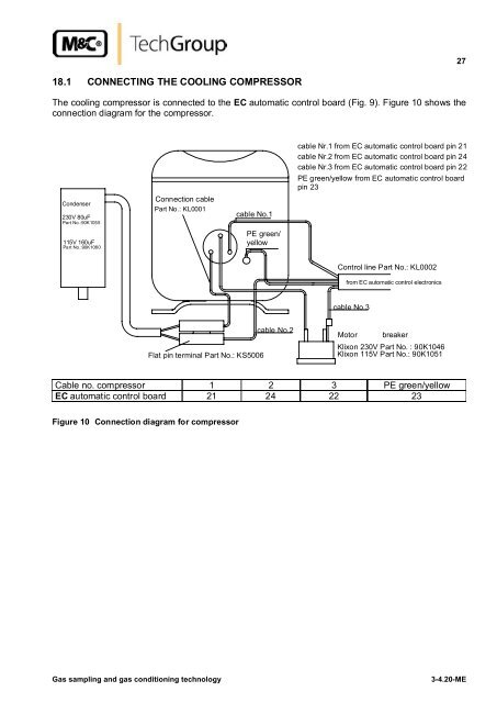
2718.1 CONNECTING THE COOLING COMPRESSORThe cooling compressor is connected to the EC automatic control board (Fig. 9). Figure 10 shows theconnection diagram for the compressor.Condenser230V 80uFPart No.:90K1055115V 160uFPart No.:90K1060Connection cablePart No.: KL0001cable No.1PE green/yellowcable Nr.1 from EC automatic control board pin 21cable Nr.2 from EC automatic control board pin 24cable Nr.3 from EC automatic control board pin 22PE green/yellow from EC automatic control boardpin 23Control line Part No.: KL0002from EC automatic control electronicscable No.3Flat pin terminal Part No.: KS5006cable No.2MotorbreakerKlixon 230V Part No. : 90K1046Klixon 115V Part No.: 90K1051Cable no. compressor 1 2 3 PE green/yellowEC automatic control board 21 24 22 23Figure 10 Connection diagram for compressor<strong>Gas</strong> sampling and gas conditioning technology3-4.20-ME


