High Voltage Cables - Prysmian Group - Elektroskandia
High Voltage Cables - Prysmian Group - Elektroskandia
High Voltage Cables - Prysmian Group - Elektroskandia

You also want an ePaper? Increase the reach of your titles
YUMPU automatically turns print PDFs into web optimized ePapers that Google loves.
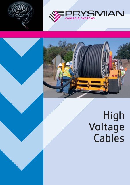
<strong>High</strong><strong>Voltage</strong><strong>Cables</strong>
<strong>High</strong> <strong>Voltage</strong> <strong>Cables</strong>The history of cablesWith long experience since 1912 <strong>Prysmian</strong> <strong>Cables</strong>and Systems Oy is today one of the leading cablemanufacturers in the world.TodayThe <strong>Prysmian</strong> <strong>Group</strong> has more than 50 productionplants in several countries on all continents.In addition to this the company has a worldwidenetwork of sales and representative offices.<strong>Prysmian</strong> <strong>Cables</strong> and Systems Oy, located in Pikkala,Finland, produces energy cables - from extra high(400 kV ) to low voltage, for land, submarine andoverhead applications - along with a wide range ofaccessories. All our products can be tailored tomeet the customer’s requirements.Our company has been the forerunner in high voltagecable technology for several decades. We haveexperience in supplying all types of high voltagecable systems throughout the world with full turnkey capability.2
<strong>High</strong> <strong>Voltage</strong> <strong>Cables</strong>Environmental andreliability aspectsWhen planning a new supply route, considerationof the environment is becoming more and moreimportant due to regulation and public opinion.The XLPE cables are environmentally friendlyand safe.The cable system is invisible. The required right ofway is very small and normally after the installationthe land can be used again for its original purpose.This can result in considerable savings.Reducing the electrical and magneticfields is also becoming moreimportant. The cable systemcan be designed accordingto different magnetic fieldrequirements, and theexternal electrical fieldsare zero.Cable systems offerbetter safety to bothworkers and general public,with fewer dangeroussituations due to accidentalcontacts or flashovers.Reliability of the network is an importantfactor because the loss of supply has high costconsequences. Cable systems are less vulnerablefor failures compared to overhead lines.<strong>Prysmian</strong> sets <strong>High</strong> StandardsPartial discharges in the cable's insulation areregarded as one of the main reasons for electricalbreakdown. Most recognized national and internationalstandards permit discharges of 5 pC.However, our policy is not to allow deliveries ofcables with any detectable discharges. Our newtest set-up allows testing of up to 400 kV cablesat a measuring sensitivity which is considerablybetter than the above requirement.We are certified according to ISO 9001 Qualityand ISO 14001 Environmental Management Systemstandards for our activities.3
<strong>High</strong> <strong>Voltage</strong> <strong>Cables</strong>123456712345678HXLMK / AHXLMKSingle core XLPE insulatedpower cable with lead sheathConductorLongitudinally watertight segmental strandedand compacted copper or aluminiumBinder tapesSemiconducting waterblocking tapes and bindertapesConductor screenExtruded semiconducting copolymer compoundInsulationExtruded superclean XLPE compoundInsulation screenExtruded semiconducting copolymer compoundBeddingSemiconducting waterblocking tapesMetallic sheathExtruded lead, alloy EOuter sheathExtruded PE, PVC or HFFR87
<strong>High</strong> <strong>Voltage</strong> <strong>Cables</strong>Sample ConstructionsRated voltagesU o /U = 64/110 kVU m = 123 kVU p = 550 kVRated temperatures• Maximum permissible temp. ofconductor in continuous use 90°C• Maximum permissible temp. ofconductor in short-circuit 250°C(for durations up to 5 sec. )Standard IEC 60840123 kV <strong>Cables</strong> 64/110 kVSingle core, XLPE-insulatedhigh voltage power cablesNominal cross-sectional area of conductormm 230050080012001600Constructional dataOuter diameterWith aluminium conductorWith copper conductorNet weightWith aluminium conductorwith Pb sheathWith copper conductorRecommended minimum bending radius during layingmmmmkg/kmkg/kmm67678100100501.2747410100135001.3828313000185001.5929416500245001.79910219000300001.8Electrical properties at 110 kV and 50 HzAluminiumconductorCopperconductorMaximum DC-resistanceEffectiveresistance,screensbonded atboth endsMaximum DC-resistanceEffectiveresistance,screensbonded atboth endsFlatformationTrefoilformationFlatformationTrefoilformationDC-resistance of metallic screen at 20°C approx.InductanceOperating capacitanceCharging currentFlat formationTrefoil formationConductortemperatureConductortemperatureConductortemperatureConductortemperatureat 20°C20°C65°C90°C20°C65°C90°Cat 20°C20°C65°C90°C20°C65°C90°CΩ/kmΩ/kmΩ/kmΩ/kmΩ/kmΩ/kmΩ/kmΩ/kmΩ/kmΩ/kmΩ/kmΩ/kmΩ/kmΩ/kmΩ/kmmH/kmmH/kmµF/kmA/km0.10000.1230.1390.1480.1070.1250.1340.06010.0840.0920.0960.0680.0770.0830.620.610.420.153.30.06050.0880.0960.1010.0690.0790.0850.03660.0650.0680.0700.0460.0510.0540.510.580.390.203.80.03670.0700.0720.0740.0480.0530.0560.02210.0560.0560.0570.0340.0370.0380.420.550.360.254.60.02470.0640.0640.0640.0380.0410.0430.01510.0520.0500.0500.0250.0270.0280.340.530.350.305.60.01860.0610.0600.0600.0340.0360.0370.01130.0520.0490.0480.0230.0240.0240.300.520.330.306.2Continuous current-carrying capacitiesConductorAluminiumCopper<strong>Cables</strong>laidIngroundof 15°CIn airof 25°CIngroundof 15°CIn airof 25°CConductortemperature65°C90°C90°C65°C90°C90°CLayingformationFlatTrefoilFlatTrefoilFlatTrefoilFlatTrefoilFlatTrefoilFlatTrefoilScreencircuitOpenClosedOpenClosedOpenClosedOpenClosedOpenClosedOpenClosedOpenClosedOpenClosedOpenClosedOpenClosedOpenClosedOpenClosedAAAAAAAAAAAAAAAAAAAAAAAA43541041541051049049048567564560560056051053052066061063062087081577577057551554553067561564063091585081580573062568566586075081079011651035103510207506257006758857508308001235107510851070935720860815111087510259751555127013501330905690830785107584099094015201230132513001190790108598514109701295119019951450174516551035730930860123089511101035177513501525149013808251230108016401015147513102360156520401900Maximum permissible short-circuit currents for short-circuit duration of one secondAluminium conductorCopper conductorkAkA28.342.847.271.475.6114.2113.4171.4151.2228.59
<strong>High</strong> <strong>Voltage</strong> <strong>Cables</strong>Sample ConstructionsRated voltagesU o /U = 76/132 kVU m = 145 kVU p = 650 kVRated temperatures• Maximum permissible temp. ofconductor in continuous use 90°C• Maximum permissible temp. ofconductor in short-circuit 250°C( for durations up to 5 sec. )Standard IEC 60840145 kV <strong>Cables</strong> 76/132 kVSingle core, XLPE-insulatedhigh voltage power cablesNominal cross-sectional area of conductormm 2500800120016002000Constructional dataOuter diameterWith aluminium conductorWith copper conductorNet weightWith aluminium conductorwith Pb sheathWith copper conductorRecommended minimum bending radius during layingmmmmkg/kmkg/kmm747410100135001.3828313000185001.5929416500245001.79910219000300001.810510922000355001.9Electrical properties at 132 kV and 50 HzAluminiumconductorCopperconductorMaximum DC-resistanceEffectiveresistance,screensbonded atboth endsMaximum DC-resistanceEffectiveresistance,screensbonded atboth endsFlatformationTrefoilformationFlatformationTrefoilformationDC-resistance of metallic screen at 20°C approx.InductanceOperating capacitanceCharging currentFlat formationTrefoil formationConductortemperatureConductortemperatureConductortemperatureConductortemperatureat 20°C20°C65°C90°C20°C65°C90°Cat 20°C20°C65°C90°C20°C65°C90°CΩ/kmΩ/kmΩ/kmΩ/kmΩ/kmΩ/kmΩ/kmΩ/kmΩ/kmΩ/kmΩ/kmΩ/kmΩ/kmΩ/kmΩ/kmmH/kmmH/kmµF/kmA/km0.06050.0890.0970.1010.0700.0800.0850.03660.0650.0680.0700.0460.0520.0550.510.580.390.204.60.03670.0700.0730.0740.0480.0530.0560.02210.0570.0570.0570.0350.0370.0390.420.550.360.255.50.02470.0640.0640.0640.0390.0420.0430.01510.0520.0510.0500.0250.0270.0280.340.530.350.306.70.01860.0610.0600.0600.0340.0360.0370.01130.0520.0500.0480.0230.0240.0240.300.520.330.307.50.01490.0620.0600.0590.0320.0340.0340.00900.0540.0510.0490.0220.0220.0220.260.510.320.358.2Continuous current-carrying capacitiesConductorAluminiumCopper<strong>Cables</strong>laidIngroundof 15°CIn airof 25°CIngroundof 15°CIn airof 25°CConductortemperature65°C90°C90°C65°C90°C90°CLayingformationFlatTrefoilFlatTrefoilFlatTrefoilFlatTrefoilFlatTrefoilFlatTrefoilScreencircuitOpenClosedOpenClosedOpenClosedOpenClosedOpenClosedOpenClosedOpenClosedOpenClosedOpenClosedOpenClosedOpenClosedOpenClosedAAAAAAAAAAAAAAAAAAAAAAAA5705155405306756156406309158458158057256206856608607508107901165103510301020745620695670885750825800123510751085107093572086081011108751025975155512651350132590568583078010758409909351520123013251300119079010859851410970129011851990145017451650103072592585512308951110103517701345152014901375820123010751635101514701310236015652035189511357451000905135592012001100198014151680163515308251330113018251030160013802655162022602075Maximum permissible short-circuit currents for short-circuit duration of one secondAluminium conductorCopper conductorkAkA47.271.475.6114.2113.4171.4151.2228.5189.1285.710
<strong>High</strong> <strong>Voltage</strong> <strong>Cables</strong>Sample ConstructionsRated voltagesU o /U = 89/154 kVU m = 170 kVU p = 750 kVRated temperatures• Maximum permissible temp. ofconductor in continuous use 90°C• Maximum permissible temp. ofconductor in short-circuit 250°C(for durations up to 5 sec.)Standard IEC 60840170 kV <strong>Cables</strong> 89/154 kVSingle core, XLPE-insulatedhigh voltage power cablesNominal cross-sectional area of conductorNominal cross-sectional area of screenmm 2mm 25009580095120095160095200095Constructional dataOuter diameterWith aluminium conductorWith copper conductorNet weightWith aluminium conductorwith Cu screenWith copper conductorRecommended minimum bending radius during layingmmmmkg/kmkg/kmm8080615093001.688897700135001.8971009600180002.010410711500220002.111011413000265002.3Electrical properties at 154 kV and 50 HzAluminiumconductorCopperconductorMaximum DC-resistanceEffectiveresistance,screensbonded atboth endsMaximum DC-resistanceEffectiveresistance,screensbonded atboth endsFlatformationTrefoilformationFlatformationTrefoilformationDC-resistance of metallic screen at 20°C approx.InductanceOperating capacitanceCharging currentFlat formationTrefoil formationConductortemperatureConductortemperatureConductortemperatureConductortemperatureat 20°C20°C65°C90°C20°C65°C90°Cat 20°C20°C65°C90°C20°C65°C90°CΩ/kmΩ/kmΩ/kmΩ/kmΩ/kmΩ/kmΩ/kmΩ/kmΩ/kmΩ/kmΩ/kmΩ/kmΩ/kmΩ/kmΩ/kmmH/kmmH/kmµF/kmA/km0.06050.1180.1260.1310.0810.0900.0950.03660.0940.0970.0990.0570.0610.0640.200.600.410.174.70.03670.0950.0980.1010.0580.0620.0650.02210.0810.0820.0830.0450.0460.0470.200.570.380.205.60.02470.0840.0850.0860.0480.0490.0510.01510.0720.0720.0720.0350.0350.0360.200.550.360.246.80.01860.0790.0790.0790.0430.0430.0440.01130.0680.0680.0670.0310.0310.0310.200.530.350.277.50.01490.0790.0790.0790.0430.0430.0440.00900.0660.0650.0650.0290.0290.0290.200.520.330.298.2Continuous current-carrying capacitiesConductorAluminiumCopper<strong>Cables</strong>laidIngroundof 15°CIn airof 25°CIngroundof 15°CIn airof 25°CConductortemperature65°C90°C90°C65°C90°C90°CLayingformationFlatTrefoilFlatTrefoilFlatTrefoilFlatTrefoilFlatTrefoilFlatTrefoilScreencircuitOpenClosedOpenClosedOpenClosedOpenClosedOpenClosedOpenClosedOpenClosedOpenClosedOpenClosedOpenClosedOpenClosedOpenClosedAAAAAAAAAAAAAAAAAAAAAAAA57546554051068056064060591579082079072553567062085565080074011459251020965750550690630885665820760123598010851025935610845745111575010109001550112013451240905610815730107574597588015151125132012251190680105588514108301265107519851295172515351035650910795123579510959701765123515151385137571511859601635880143011752340141020051735113567598584513608301185103519801325167515101530740129010201825915155512502640149522251890Maximum permissible short-circuit currents for short-circuit duration of one secondAluminium conductorCopper conductorkAkA47.271.475.6114.2113.4171.4151.2228.5189.1285.711
<strong>High</strong> <strong>Voltage</strong> <strong>Cables</strong>Sample ConstructionsRated voltagesU o /U = 127/220 kVU m = 245 kVU p = 1050 kVRated temperatures• Maximum permissible temp. ofconductor in continuous use 90°C• Maximum permissible temp. ofconductor in short-circuit 250°C(for durations up to 5 sec.)Standard IEC 62067245 kV <strong>Cables</strong> 127/ 220 kVSingle core, XLPE-insulatedhigh voltage power cablesNominal cross-sectional area of conductorNominal cross-sectional area of screenmm 2mm 25009580095120095160095200095Constructional dataOuter diameterWith aluminium conductorWith copper conductorNet weightWith aluminium conductorwith Cu screenWith copper conductorRecommended minimum bending radius during layingmmmmkg/kmkg/kmm91917500110001.8981009000150002.010610811000190002.211311513000235002.311912214500280002.4Electrical properties at 220 kV and 50 HzAluminiumconductorCopperconductorMaximum DC-resistanceEffectiveresistance,screensbonded atboth endsMaximum DC-resistanceEffectiveresistance,screensbonded atboth endsFlatformationTrefoilformationFlatformationTrefoilformationDC-resistance of metallic screen at 20°C approx.InductanceOperating capacitanceCharging currentFlat formationTrefoil formationConductortemperatureConductortemperatureConductortemperatureConductortemperatureat 20°C20°C65°C90°C20°C65°C90°Cat 20°C20°C65°C90°C20°C65°C90°CΩ/kmΩ/kmΩ/kmΩ/kmΩ/kmΩ/kmΩ/kmΩ/kmΩ/kmΩ/kmΩ/kmΩ/kmΩ/kmΩ/kmΩ/kmmH/kmmH/kmµF/kmA/km0.06050.1200.1270.1320.0830.0910.0960.03660.0960.0990.1010.0590.0620.0650.200.620.440.145.80.03670.0970.1000.1020.0600.0630.0660.02210.0790.0800.0810.0420.0430.0450.200.580.400.187.30.02470.0850.0860.0870.0490.0500.0520.01510.0730.0730.0730.0350.0360.0360.200.560.380.218.30.01860.0800.0800.0800.0430.0440.0450.01130.0690.0680.0680.0320.0310.0310.200.540.360.239.20.01490.0770.0760.0760.0400.0400.0410.00900.0670.0660.0650.0300.0290.0290.200.530.350.2510.0Continuous current-carrying capacitiesConductorAluminiumCopper<strong>Cables</strong>laidIngroundof 15°CIn airof 25°CIngroundof 15°CIn airof 25°CConductortemperature65°C90°C90°C65°C90°C90°CLayingformationFlatTrefoilFlatTrefoilFlatTrefoilFlatTrefoilFlatTrefoilFlatTrefoilScreencircuitOpenClosedOpenClosedOpenClosedOpenClosedOpenClosedOpenClosedOpenClosedOpenClosedOpenClosedOpenClosedOpenClosedOpenClosedAAAAAAAAAAAAAAAAAAAAAAAA5654605255006655556255958757607957707155356606108506457907301115905100595573054067061586565580074011609351040985955620865760113575510359201520110513551250890600800715106073596086514501085128511951170670103086513908251235105518951250167014951015640895780121578510809501690119014751350135070511609451610870140011602235135519401690111566596583013408201170101518901270162514701500730125510001795905152512302510143021501835Maximum permissible short-circuit currents for short-circuit duration of one secondAluminium conductorCopper conductorkAkA47.271.475.6114.2113.4171.4151.2228.5189.1285.712
<strong>High</strong> <strong>Voltage</strong> <strong>Cables</strong>Sample ConstructionsRated voltagesU o /U = 200/345 kVU m = 362 kVU p = 1175 kVRated temperatures• Maximum permissible temp. ofconductor in continuous use 90°C• Maximum permissible temp. ofconductor in short-circuit 250°C(for durations up to 5 sec.)Standard IEC 62067Nominal cross-sectional area of conductorNominal cross-sectional area of screenConstructional dataOuter diameterNet weightwith Cu screenWith aluminium conductorWith copper conductorWith aluminium conductorWith copper conductorRecommended minimum bending radius during laying362 kV <strong>Cables</strong> 200/345 kVSingle core, XLPE-insulatedhigh voltage power cablesmm 2mm 2mmmmkg/kmkg/kmm6309511111111000150002.28009511211211500165002.212009511511712500205002.316009512212414500250002.520009512813116000295002.6Electrical properties at 345 kV and 50 HzAluminiumconductorCopperconductorMaximum DC-resistanceEffectiveresistance,screensbonded atboth endsMaximum DC-resistanceEffectiveresistance,screensbonded atboth endsFlatformationTrefoilformationFlatformationTrefoilformationDC-resistance of metallic screen at 20°C approx.InductanceOperating capacitanceCharging currentFlat formationTrefoil formationConductortemperatureConductortemperatureConductortemperatureConductortemperatureat 20°C20°C65°C90°C20°C65°C90°Cat 20°C20°C65°C90°C20°C65°C90°CΩ/kmΩ/kmΩ/kmΩ/kmΩ/kmΩ/kmΩ/kmΩ/kmΩ/kmΩ/kmΩ/kmΩ/kmΩ/kmΩ/kmΩ/kmmH/kmmH/kmµF/kmA/km0.04690.1100.1140.1180.0720.0770.0810.02830.0910.0920.0930.0530.0550.0570.200.640.450.138.20.03670.1000.1020.1050.0620.0650.0680.02210.0830.0830.0840.0440.0450.0460.200.610.420.169.90.02470.0890.0890.0900.0510.0520.0530.01510.0760.0750.0750.0370.0370.0370.200.580.390.1811.60.01860.0830.0820.0830.0460.0450.0460.01130.0720.0700.0700.0340.0320.0330.200.560.380.2012.70.01490.0800.0790.0790.0420.0420.0420.00900.0700.0680.0680.0320.0300.0300.210.550.360.2213.9Continuous current-carrying capacitiesConductorAluminiumCopper<strong>Cables</strong>laidIngroundof 15°CIn airof 25°CIngroundof 15°CIn airof 25°CConductortemperature65°C90°C90°C65°C90°C90°CLayingformationFlatTrefoilFlatTrefoilFlatTrefoilFlatTrefoilFlatTrefoilFlatTrefoilScreencircuitOpenClosedOpenClosedOpenClosedOpenClosedOpenClosedOpenClosedOpenClosedOpenClosedOpenClosedOpenClosedOpenClosedOpenClosedAAAAAAAAAAAAAAAAAAAAAAAA635500590550760605705665990845905870805570735665960695880805125099511351070715535660605855655790735112592510209759356108457451120750102090514801100133512358705957857001045730945855142010801265118011406651005850137082012151045185512501645148099563087576511957801065940165011851455133513206951130925158586513751145218513601910167510906559458151320815115510051845126516051460146072012259751765895149512152455143521201825Maximum permissible short-circuit currents for short-circuit duration of one secondAluminium conductorCopper conductorkAkA59.590.075.6114.2113.4171.4151.2228.5189.1285.713
<strong>High</strong> <strong>Voltage</strong> <strong>Cables</strong>Sample ConstructionsRated voltagesU o /U = 220/400 kVU m = 420 kVU p = 1425 kVRated temperatures• Maximum permissible temp. ofconductor in continuous use 90°C• Maximum permissible temp. ofconductor in short-circuit 250°C(for durations up to 5 sec.)Standard IEC 62067Nominal cross-sectional area of conductorNominal cross-sectional area of screenConstructional dataOuter diameterWith aluminium conductorWith copper conductorNet weightWith aluminium conductorwith Cu screenWith copper conductorRecommended minimum bending radius during laying420 kV <strong>Cables</strong> 220/400 kVSingle core, XLPE-insulatedhigh voltage power cablesmm 2mm 2mmmmkg/kmkg/kmm8009512312213000185002.410009512412313500205002.512009512412514000220002.516009512712815500260002.6Electrical properties at 400 kV and 50 HzAluminiumconductorCopperconductorMaximum DC-resistanceEffectiveresistance,screensbonded atboth endsMaximum DC-resistanceEffectiveresistance,screensbonded atboth endsFlatformationTrefoilformationFlatformationTrefoilformationDC-resistance of metallic screen at 20°C approx.InductanceOperating capacitanceCharging currentFlat formationTrefoil formationConductortemperatureConductortemperatureConductortemperatureConductortemperatureat 20°C20°C65°C90°C20°C65°C90°Cat 20°C20°C65°C90°C20°C65°C90°CΩ/kmΩ/kmΩ/kmΩ/kmΩ/kmΩ/kmΩ/kmΩ/kmΩ/kmΩ/kmΩ/kmΩ/kmΩ/kmΩ/kmΩ/kmmH/kmmH/kmµF/kmA/km0.03670.1010.1030.1060.0630.0660.0690.02210.0840.0840.0840.0450.0460.0470.200.620.440.1410.30.02910.0940.0950.0960.0560.0570.0590.01760.0790.0780.0790.0400.0400.0410.200.600.420.1611.50.02470.0900.0900.0910.0520.0520.0540.01510.0770.0760.0760.0380.0380.0380.200.590.410.1712.30.01860.0850.0830.0840.0470.0460.0470.01130.0740.0710.0710.0350.0330.0330.210.570.380.1914.0Continuous current-carrying capacitiesConductorAluminiumCopper<strong>Cables</strong>laidIngroundof 15°CIn airof 25°CIngroundof 15°CIn airof 25°CConductortemperature65°C90°C90°C65°C90°C90°CLayingformationFlatTrefoilFlatTrefoilFlatTrefoilFlatTrefoilFlatTrefoilFlatTrefoilScreencircuitOpenClosedOpenClosedOpenClosedOpenClosedOpenClosedOpenClosedOpenClosedOpenClosedOpenClosedOpenClosedOpenClosedOpenClosedAAAAAAAAAAAAAAAAAAAAAAAA71554066060585565579073511259351025980930615840740111075510109051450110013201230800570725660960700875805126510151150109010456459308051255795113098516701195150013758655957757001040730940855139010801250117511306609958401360820121010351825125016301470980625865760118577510559351630118514401330130069011159101570860136511352160135518951665Maximum permissible short-circuit currents for short-circuit duration of one secondAluminium conductorCopper conductorkAkA75.6114.294.5142.8113.4171.4151.2228.514
<strong>High</strong> <strong>Voltage</strong> <strong>Cables</strong>Usingthe tablesThe electrical properties and continuous currentratings apply for lead sheathed cables with ournormal sheath thickness. The thickness of sheathand especially the cross-section of copper screencan be adjusted according to the required shortcircuit rating of sheath or screen.Where loading is cyclic, appreciable increase incurrent capacities may be justified. Refer to IECPublication 60853 for calculation of the cyclicratings.In cable circuits having no magnetic saturatingmaterials the positive and negative sequenceimpedances are equal and can be deduced fromthe tabulated effective resistance and inductancevalues corrected as required for frequencies otherthan 50Hz.Zero sequence impedance for solidly bondedsystems can be roughly estimated as the sumof the resistances of conductor and sheath anda reactance of 0.05 to 0.1 ohms /km dependingon the proportion of diameters of sheath andconductor at 50 to 60 Hz. For single point bondedsystems the zero sequence impedance dependson the ground wires and any other groundedmetallic objects along the cable route.Selectinga powercableDifferent kinds of power cable constructions arerequired to transport electrical energy fromthe power station to the consumer.The following factors are important when selectinga suitable cable construction:• Maximum operating voltage• Insulation level• Frequency• Load to be carried• Daily load curve• Magnitude and duration of possible overloadscurrents phase-to-phase and phase-to-earth• Connection between overhead and cable line(whether directly or via a transformator)• Insulation level of equipment(bareconductor insulators, arresters, etc.)• <strong>Voltage</strong> drop• Length of line• Profile of line• Mode of installation:- underground (whether directly or in ducts)- in air ( if in a tunnel, the dimensions andmode of ventilation of the tunnel )• Chemical and physical properties of the soil:- whether rocky, sandy, clay or boggy;moist or dry- chemical agents liable to cause corrosion etc.- the maximum thermal resistivity of the soil• Maximum and minimum ambient air andsoil temperatures, bearing in mind nearbyhotwater pipes and other factors liable toheat the cables• Specifications and requirements to be met• The cable should be economical to use;an optimum cross-sectional area can becalculated based on the capital costs ofthe cable and its running costs incurred bythe power losses in the cable15
<strong>High</strong> <strong>Voltage</strong> <strong>Cables</strong><strong>Voltage</strong>sCompleteSystemSupplyStandardsCustomdesignedcablesRated voltageThe voltage which forms the basis for certainoperating characteristics and test conditions iscalled the rated voltage and is denotedU o /U whereU o = the voltage between the conductor andearth or earthed metallic cover(concentric conductor, screen,armouring, metal sheath)U = the voltage between the phase conductorsOperating voltageU m= the maximum continuously permissibleoperating voltage of the network at any timeIt is essential that the accessories and cables aretype-tested together forming a complete system.We supply a full range of accessories and fittingsfor the splicing and terminating as well as toolsThe cables described in this catalogue are ourstandard types, and their performance has beenproven in operation.Power cables ranging from 72.5 kV to 420 kVcan be manufactured also according to otherstandards (eg. AEIC, VDE, BS, SEN ), regulationsor specifications in-line with the customers’requirements.or in any part of the network, excludingtemporary fluctuations such as those occuringduring switching or faults.Relationship between U o /U and U m in threephase systems are as follows according toIEC specifications:U o/U kV 36/66 64/110 76/132 127/220 190/345 220/400U mkV 72.5 123 145 245 362 420and according to USA Standard C-84: 1-1995U o/U kV 40/69 66/115 80/138 132/230 200/345U mkV 72.5 121 145 242 362and equipment, complete with instructions forinstallation. We also provide planning andsupervision of the complete system packages.Construction and tests are in accordance with IECpublications where applicable.CircularMilsIn American standards the cross section areais expressed in Circular Mils Ac.Cross-Sections in mm 2 converted into Circular MilsA =Ac1973.5 mm2mm 2 185 300 500 800 1200 1600 2000kcmil 365 590 990 1580 2370 3160 3950WeightsanddimensionsWeights, dimensions and characteristic dataare approximate. Deviations due todifferent constructions are reserved.16
<strong>High</strong> <strong>Voltage</strong> <strong>Cables</strong>Our standard embossed or surface printed outersheath marking on round cables consists of:• name of manufacturer• type designation, cross-sectional area of conductor,rated voltage and year of manufacture• continuous length marking every meter orevery few feet.Example:AHXLMK 1x 300 mm 2 132 kV 2006 1234 mSheathmarkingMinimum permissible bending radii during laying:• during pulling of power cables, the bendingradii should not be smaller than the valuesgiven on pages 8-14• in the case of single bends, the above valuesmay be reduced to a min. of 70 % if thecables are carefully and evenly bent onlyonce before a termination ( around a prefabricatedbow, if necessary).Max. permissible pulling tension during laying:• during laying of power cables particularattention must be paid to the permissibletensile forces• permissible tensile forces when pulling bycable pulling grip:F = A x 15 N/mm 2(cable with Al-conductor)F = A x 20 N/mm 2(cable with Cu-conductor)maximum value in both cases is 8500 NDirect Current resistanceThe maximum DC resistance values of conductorsat 20°C are shown in cable standards.The DC resistance at other conductor temperaturesmay be calculated using the equation:R=R 20[1+α 20(t - 20°C)]R= DC resistance at temperature t, Ω/kmR 20= DC resistance of cond. at 20°C, Ω/kmt = temperature of conductor, °Cα 20= temperature coefficient of the resistanceat 20°C, 1/°Cfor copper conductors α 20= 0.00393for Al. cond. and sheath α 20= 0.00403for lead alloy sheath α 20= 0.00400On pages 8-14 are given:• maximum DC resistance of conductors at20°C ( in accordance with IEC 60228)• calculated DC resistance of metallic sheathsand metallic screens at 20°C• maximum recommended tensile forces whenpulling eye is attached to the conductor:Al-conductors; ≤ 800 mm 2 , F = A x 70 N/mm 2> 800 mm 2 , F = A x 50 N/mm 2Cu-conductors; ≤ 800 mm 2 , F = A x 90 N/mm 2> 800 mm 2 , F = A x 70 N/mm 2A = cross-sectional area of conductor in mm 2(without screen and conc. conductor)Minimum permissible cable temperature duringlaying:• XLPE insulated cables U > 30 kV; -5°C forHFFR and PVC-sheath, -15°C for PE-sheath.At lower temperature the cables must beadequately warmed up beforehand.This can be done by storing the cables in aheated room for several days or by means ofspecial equipment.LayinginformationEffective resistanceResistancesThe effective resistance (= alternating currentresistance) is made up of the DC resistance andthe extra resistance, which takes into accountadditional losses caused by the currentdisplacement in the conductor ( skin effect,proximity effect), dielectrical losses in insulationcirculating currents in the metal sheath or screenand eddy currents as well as magnetic reversal inthe armour.On pages 8-14 are given effective resistanceof conductors at 20°C and at maximum conductortemperature. They are based on the followingpresumptions:• frequency 50 Hz• closed screen circuit• distance between single core cables- in case of flat formation = one cable diam.- in case of trefoil formation = cables touchingeach other.The values for the inductance of single core cableshave been calculated based on the followingpresumptions:• open screen circuit• distance between single core cables- in case of flat formation = one cable diam.- in case of trefoil formation = cables touchingeach other.InductanceThe values for the operating capacitance of thecables are average values based on measurementsand calculations.The values for the charging current are valid ata temperature of 20°C, at a frequency of 50 Hzand at a rated voltage of the cable.The values of capacitance, charging currentand earth fault current will not change whenusing XLPE insulated cables when the temperatureincreases from 20°C to the maximumpermissible continuous conductor temperature.Operatingcapacitance,chargingcurrent andearth faultcurrent17
<strong>High</strong> <strong>Voltage</strong> <strong>Cables</strong>ContinuouscurrentcarryingcapacityA separate group of three single core cables canbe continuously loaded according to the tableson pages 8 to 14 if the presumptions below arefulfilled. Correction factors for other installationsare given in tables 1-7.The current-carrying capacities are calculated inaccordance with the IEC Publication 60287 andunder the presumptions given below.Presumptions• One three-phase group of single core cables• Maximum permissible temperature of innerconductor in continuous use:• XLPE insulated cables 90°C• Ambient air temperature 25°C• Ground temperature 15°C• Depth of laying of cables 1. 0 m• Distance between single core cables:- in case of flat formation = one cable diam.- in case of trefoil formation = cables touchingeach other• Thermal resistivity of soil 1. 0 K m/W• Cable in air = heat dissipation conditionssame as if cables in free air.• Open screen circuit in single core cablegroup = circuit of metal sheaths, concentricconductors or metallic screens connectedto each other and earthed at one pointonly = screens bonded at a single point.In addition, screen circuit is considered openwhen cross-bonded at equal interval.• Closed screen circuit in single core cablegroup = circuit of metal sheaths, concentricconductors or metallic screens connectedto each other at both ends of the group andearthed at least at one end = screens bondedat both ends.XLPE-insulated cables buried directly in groundXLPE-insulated cables can continuously be loadedto a conductor temperature of 90°C.In underground installations, if a cable in theground is continuously operated at this highestrated conductor temperature, the thermal resistivityof the soil surrounding the cable may in the courseof time increase from its original value as a resultof the drying-out processes. As a consequence,the conductor temperature may greatly exceedthe highest rated value.Using single-point bonding or cross-bondinginstead of both-end bonding results in considerableincrease in current carrying capacity.ShortcircuitcurrentcapacityWhen planning cable installations, care has to betaken that the cables and fittings chosen arecapable of withstanding the expected dynamicand thermal short-circuit stresses.The dynamic stresses depend on the max.asymmetric short-circuit current and the thermalstresses on the mean short-circuit current.Dynamic stressesGenerally cables and their standard accessorieswill withstand the dynamic stresses under shortcircuitconditions, but near the power stations itis important to take into consideration the dynamicshort-circuit current capacity and to pay attentionto the technique of installation.Thermal stressesOn pages 8 to 14 are given the max. permissibleshort-circuit currents for short-circuit durationof one second and the values are based on thefollowing presumptions:• before short-circuit the temperature ofconductors = max. permissible temperatureof conductor in continuous use• max. permissible temperature of conductor inshort-circuit is 250°C for XLPE-insulated cables• the permissible short-circuit currents forshort-circuit duration of 0. 2 up to 5 secondsmay be calculated by multiplying the value ofmax. permissible short-circuit current for shortcircuitduration of one second by the figure1/ t, where t is the duration of short-circuitin seconds.Correctionfactors forthe currentcarryingcapacityThe following tables of correction factors are tobe applied to the current-carrying capacity wheninstallation conditions vary from the presumptionsabove.The rating for most conditions can be quicklyestimated by multiplying the continuous currentcarryingcapacity value by the correction factorsgiven in the appropriate tables 1-7.Table 1.Correctionfactors forgroups ofcables burieddirectlyin groundSpacing betweengroups of cables, mm0 (touching )7025020.790.850.87The values apply to groups of three single core cables ( in trefoil or flat formation)without or with spacing between the cable groups horizontally placed.Numbers of groups of single core cables beside each other30.690.750.7940.630.680.7550.580.640.7260.550.600.6980.500.560.66100.460.530.64Table 2.Correctionfactors fordifferentthermalresistivitiesof soilThermal resistivity of soil Km/WCorrection factorExamples of thermal resistivities of soil:• dry sand (moisture content 0% )• dry gravel and clay0.71.103.0 K m/W1.5 K m/W1.01.001.20.921.50.852.00.752.50.69• semi-dry gravel and sand (moisture content 10% )• semi-dry and moist gravel• moist clay and sand ( moisture content 25%)3.00.631.2 K m/W1.0 K m/W0.7 K m/W18
<strong>High</strong> <strong>Voltage</strong> <strong>Cables</strong>Table 3.Correctionfactors fordifferentinstallationdepths in groundDepth of laying, mRating factor0.50-0.701.050.71-0.901.020.91-1.101.001.11-1.300.971.31-1.500.95Table 4.Correctionfactors fordifferent groundtemperaturesConductor temperatureC°90807065-51.131.141.171.1801.101.111.131.1451.061.071.091.10101.031.041.041.05Ground temperature, C°151.001.001.001.00200.960.960.950.95250.930.920.900.89300.890.880.850.84350.860.830.800.77400.820.780.730.71450.770.730.670.63Table 5.Correctionfactors fordifferent cablesin unfilledplastic pipesSpacing betweenthe tubes, mm0 (touching)7025010.8020.750.750.7530.650.700.70Numbers of tubes beside each other40.600.650.7050.600.600.7060.550.600.6580.550.550.65100.500.550.65For parallel ducts with a group of three single core cables in each andwith the cables equally loaded the current-carrying capacity indicatedon pages 8 to 14 for cables buried directly in ground shall be reducedby correction factors given above.The reduction in current carrying capacity can be avoided if the pipesafter cable pulling are filled with material thermally equalto the ambient ground.If factors in table 5 are used, factors in table 1 are not applicable.Table 6.Correctionfactors fordifferent ambientair temperaturesConductor temperatureC°90807065101.121.141.181.20151.081.091.121.14201.041.051.061.07251.001.001.001.00Ambient air temperature, C°30 350.95 0.900.95 0.890.93 0.860.93 0.85400.850.840.790.77450.800.770.710.68500.740.690.620.57550.680.610.520.45Table 7.Correctionfactors fordifferent groupsof three singlecore cableslaid in the airType of layingNumber of groupsOn floor<strong>Cables</strong> laid in flat formationSpacing = One cable diameter (d).Distance from the wall not less than 20 mm.1 2 3Correction factor0.92 0.89 0.8820 mmdd<strong>Cables</strong> laid in trefoil formationSpacing = Two cable diameters (2d).Distance from the wall not less than 20 mm.1 2 3Correction factor0.95 0.90 0.8820 mm2d2dThis appliesonly whenthe cabletemperaturedoes notaffect theambient airtemperature.On metal trays(restricted aircirculation)On metal laddersNumberof trays1236Numberof ladders12360.920.870.840.821.000.970.960.940.890.840.820.800.970.940.930.910.880.830.810.790.960.930.920.9020 mm20 mmdddd0.3 m0.3 m0.950.900.880.861.001.001.001.000.900.850.830.810.980.950.940.930.880.830.810.790.960.930.920.9020 mm20 mm2d2d2d2d0.3 m0.3 mArrangements where reductionof current is not necessaryThe cooling of cables in flat formationby increased spacing will get better whilethe losses in metallic screens and sheathswill increase reducing the current-carryingcapacity. Each case must be calculatedseparately.20 mm4d2d0.3 mSystems placed on topof each other20 mmOn structures or on wall1 2 3Correction factor0.94 0.91 0.89dd1 2 3Correction factor0.89 0.86 0.842d19
PRYSMIAN CABLES AND SYSTEMS OYP.O.Box 13FI-02401 Kirkkonummi, FinlandPhone +358 10 77551Fax +358 9 682 1545www.prysmian.fiA. Leppälä Oy 11/2006 5.000