E & VE - Arten Freios e Embreagens Industriais
E & VE - Arten Freios e Embreagens Industriais
E & VE - Arten Freios e Embreagens Industriais
- No tags were found...

You also want an ePaper? Increase the reach of your titles
YUMPU automatically turns print PDFs into web optimized ePapers that Google loves.
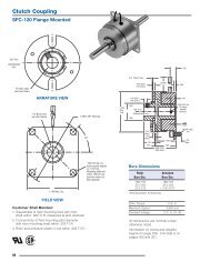
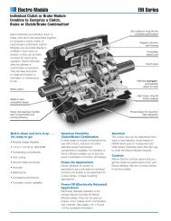
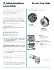
E and <strong>VE</strong> Component DescriptionsType <strong>VE</strong>Torque bar nutType E38165274SizeTorque RatingEnglishlb•in@75psi12E475 11300 128014E475 16000 181016E475 21500 243019E475 31500 356021.5E475 40500 458024E475 52000 588027E475 67000 7570SIN•m@ 5,2 bar30E600 106000 1200034E600 137000 1550040E700 225000 2540019<strong>VE</strong>475 25500 288024<strong>VE</strong>475 45200 511027<strong>VE</strong>475 58500 6610Item Component Description1 Housing half2 Housing half with valve hole3 Tube4 Torque bar (nuts required for <strong>VE</strong>)5 Friction shoe assembly6 Release spring7 Tube nut8 Friction block & rivet kit4,5,6 Torque bars, friction shoes & release springs kitCopyright Eaton Corporation, 1997, All rights reserved.C-4
Single E ElementsForm E 601 Technical Data Sizes 12 to 40Englishlb⋅in@75psirpm psi/rpm 2 lb⋅ft 2 lb in 2 in in in 3 in12E475 142314 11300 1800 1.0 E-06 5 25 151 0.18 0.06 50 12.0914E475 142213 16000 1500 1.2 E-06 8 32 139 0.37 0.18 55 14.0916E475 142214 21500 1300 1.3 E-06 14 42 167 0.37 0.18 70 16.0919E475 142215 31500 1100 2.1 E-06 26 53 202 0.37 0.18 85 19.1321.5E475 142395 40500 975 2.4 E-06 39 60 236 0.37 0.18 100 21.6324E475 142216 52000 875 2.2 E-06 56 67 257 0.37 0.18 110 24.1327E475 142334 67000 775 2.4 E-06 79 75 289 0.37 0.18 125 27.1830E600 142336 106000 700 4.1 E-06 160 125 434 0.37 0.18 175 30.1834E600 142335 137000 620 4.3 E-06 261 156 496 0.37 0.18 310 34.1840E700 142452 225000 525 9.1 E-06 520 174 864 1.25 1.06 315 40.18SizePartNumberM rTorqueRatingMaximumSpeedC sCentrifugalGainConstantWk 2JWeightMassFrictionAreaNewWornLining Thickness12E475 142314 1280 1800 0,1 E-06 0,21 11 974 5 2 0,82 30714E475 142213 1810 1500 0,1 E-06 0,34 14 897 9 5 0,90 35816E475 142214 2430 1300 0,1 E-06 0,59 19 1077 9 5 1,15 40919E475 142215 3560 1100 0,1 E-06 1,09 24 1303 9 5 1,39 48621.5E475 142395 4580 975 0,2 E-06 1,64 27 1522 9 5 1,64 54924E475 142216 5880 875 0,2 E-06 2,35 30 1658 9 5 1,80 61327E475 142334 7570 775 0,2 E-06 3,32 34 1864 9 5 2,05 69030E600 142336 12000 700 0,3 E-06 6,72 57 2799 9 5 2,87 76734E600 142335 15500 620 0,3 E-06 10,96 71 3199 9 5 5,08 86840E700 142452 25400 525 0,6 E-06 21,84 79 5573 32 27 5,17 1021SIN⋅m@ 5,2 barNewWornAirTubeCavityMaximumDrumDiameterrpm bar/rpm 2 kg⋅m 2 kg cm 2 mm mm dm 3 mmNotes: Refers to basic part number only. When ordering,the release spring force and type of friction liningsmust be specified. Dynamic torque shown, static torque approximately25% greater. Torque in each application isdependent upon release spring force, air pressureand speed. Tolerances for sizes:12 thru 27+0.010/-0.000 in (+0,25/-0,00 mm)30 thru 40+0.005/-0.000 in (+0,13/-0,00 mm) American National Pipe Thread Drum contact with worn shoes. Figures shown are with teflon or graphite slip linings.Multiply values by 1.5 for standard linings,and contact factory for possible need of reinforcedhousings. Refer to page C-42 for maximum idle RPM.C-5Copyright Eaton Corporation, 1997, All rights reserved.
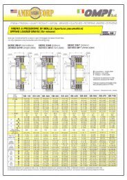
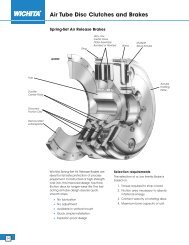
D 46D 25D 24H 6LSingle E ElementsForm E 601 Dimensional Data Sizes 12 to 40D 2WVQO 4H 2H 13GGEnglishlb⋅in@75psiDimensions in inches12E475 142314 11300 5.50 1.25 0.27 2.75 6.000 7.000 11.91 8.04 10 0.38 1/4-18 18.00 0.38 8 4.7514E475 142213 16000 5.50 1.25 0.27 2.75 7.625 8.750 13.91 9.73 12 0.38 1/4-18 15.00 0.38 10 4.7516E475 142214 21500 5.50 1.25 0.27 2.75 9.625 10.750 15.91 11.73 8 0.50 3/8-18 22.50 0.38 12 4.7519E475 142215 31500 5.50 1.25 0.27 2.75 12.125 13.750 18.91 14.73 10 0.50 3/8-18 18.00 0.38 12 4.7521.5E475 142395 40500 5.50 1.25 0.27 2.75 14.250 15.750 21.41 17.23 8 0.75 3/8-18 22.50 0.38 14 4.7524E475 142216 52000 5.50 1.25 0.27 2.75 16.750 18.250 23.91 19.73 10 0.75 3/8-18 18.00 0.38 16 4.7527E475 142334 67000 5.50 1.25 0.27 2.75 19.750 21.250 26.91 22.73 12 0.75 3/8-18 15.00 0.38 18 4.7530E600 142336 106000 7.00 1.63 0.31 3.50 21.000 23.000 29.91 24.94 14 0.75 1/2-14 12.86 0.50 14 6.0034E600 142335 137000 7.00 1.63 0.31 3.50 25.000 27.000 33.91 28.94 16 0.75 1/2-14 11.25 0.50 16 6.0040E700 142452 225000 8.13 1.75 0.31 4.06 30.000 32.000 39.91 34.63 18 0.75 1/2-14 10.00 0.56 18 7.00SizePartM rNo. Dia. No. WidthNumberTorque D 2 D 24 D 25 D 46 G H 2 H 6 H 13 LO Q4Rating(Deg.)VWNo. Dia. No. Width12E475 142314 1280 140 32 7 70 152,4 177,8 303 204 10 10 1/4-18 18,00 10 8 12114E475 142213 1810 140 32 7 70 193,7 222,3 353 247 12 10 1/4-18 15,00 10 10 12116E475 142214 2430 140 32 7 70 244,5 273,1 404 298 8 13 3/8-18 22,50 10 12 12119E475 142215 3560 140 32 7 70 308,0 349,3 480 374 10 13 3/8-18 18,00 10 12 12121.5E475 142395 4580 140 32 7 70 362,0 400,1 544 438 8 19 3/8-18 22,50 10 14 12124E475 142216 5880 140 32 7 70 425,5 463,6 607 501 10 19 3/8-18 18,00 10 16 12127E475 142334 7570 140 32 7 70 501,7 539,8 684 577 12 19 3/8-18 15,00 10 18 12130E600 142336 12000 178 41 8 89 533,4 584,2 760 633 14 19 1/2-14 12,86 13 14 15234E600 142335 15500 178 41 8 89 635,0 685,8 861 735 16 19 1/2-14 11,25 13 16 15240E700 142452 25400 206 44 8 103 762,0 812,8 1014 879 18 19 1/2-14 10,00 14 18 178SIN⋅m@ 5,2 barDimensions in millimetersCopyright Eaton Corporation, 1997, All rights reserved.C-6
Dual E ElementsForm E 603 Technical Data Sizes 12 to 34Englishlb⋅in@75psirpm psi/rpm 2 lb⋅ft 2 lb in 2 in in in 3 in12E475 22600 1800 1.0 E-06 12 88 302 0.18 0.06 100 12.0914E475 32000 1500 1.2 E-06 20 128 278 0.37 0.18 110 14.0916E475 43000 1300 1.3 E-06 38 156 334 0.37 0.18 140 16.0919E475 63000 1100 2.1 E-06 79 212 404 0.37 0.18 170 19.1321.5E475 81000 975 2.4 E-06 118 236 472 0.37 0.18 200 21.6324E475 104000 875 2.2 E-06 202 321 514 0.37 0.18 220 24.1327E475 134000 775 2.4 E-06 302 384 578 0.37 0.18 250 27.1830E600 212000 700 4.1 E-06 567 603 868 0.37 0.12 350 30.1834E600 274000 620 4.3 E-06 964 765 992 0.37 0.12 620 34.18SizeM rTorqueRatingMaximumSpeedC sCentrifugalGainConstantWk 2JWeightMassFrictionAreaNewLining Thickness12E475 2550 1800 0,1 E-06 0,50 40 1948 5 2 1,64 30714E475 3620 1500 0,1 E-06 0,84 58 1793 9 5 1,80 35816E475 4860 1300 0,1 E-06 1,60 71 2154 9 5 2,30 40919E475 7120 1100 0,1 E-06 3,32 96 2606 9 5 2,79 48621.5E475 9150 975 0,2 E-06 4,96 107 3044 9 5 3,28 54924E475 11800 875 0,2 E-06 8,48 145 3315 9 5 3,61 61327E475 15100 775 0,2 E-06 12,68 174 3728 9 5 4,10 69030E600 24000 700 0,3 E-06 23,81 273 5599 9 3 5,74 76734E600 31000 620 0,3 E-06 40,49 347 6398 9 3 10,2 868SI N⋅m@ 5,2 barNewWornWornAir TubeCavityrpm bar/rpm 2 kg⋅m 2 kg cm 2 mm mm dm 3 mmMaximumDrumDiameterNotes: Dynamic torque shown, static torque approximately25% greater. Torque in each application isdependent upon release spring force, air pressureand speed. Tolerance +0.005/-0.000 (+0,13/-0,00 mm) Refer to Form E613. Integral adapter hub usedwhich is bored and keyed for direct shaft mounting. Includes two elements and dual adapter. Drum contact with worn shoes. Figures shown are with teflon or graphite slip linings.Multiply values by 1.5 for standard linings,and contact factory for possible need of reinforcedhousings. American National Pipe Thread Size 40 has fourinlet valves Refer to page C-42 for maximum idle RPM.C-7Copyright Eaton Corporation, 1997, All rights reserved.
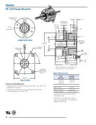
Dual E ElementsForm E 603 Dimensional Data Sizes 12 to 34Adapter hub for sizes12 and 14E475 only.VD 2WGO 4G H 5O 46.38 (162 mm)D 46LDualAdapterH 13D 42 D 46H 2Englishlb⋅in@75psiDimensions in inches12E475 22600 11.75 N/A N/A 11.91 8.40 N/A N/A 1/4-18 0.38 16 11.0014E475 32000 11.75 N/A N/A 13.91 9.73 N/A N/A 1/4-18 0.38 20 11.0016E475 43000 11.63 0.50 5.56 5.500 6.750 15.91 11.73 8 0.78 3/8-18 0.38 24 10.8819E475 63000 11.63 0.50 5.56 8.000 9.500 18.91 14.73 10 0.78 3/8-18 0.38 24 10.8821.5E475 81000 11.63 0.63 5.50 9.625 11.000 21.41 17.23 6 0.78 3/8-18 0.38 28 10.8824E475 104000 11.63 0.63 5.50 11.500 13.500 23.91 19.73 8 1.03 3/8-18 0.38 32 10.8827E475 134000 11.63 0.63 5.50 14.625 16.000 26.91 22.73 8 0.78 3/8-18 0.38 36 10.8830E600 212000 14.81 0.75 7.03 15.000 17.000 29.91 24.94 12 1.03 1/2-14 0.50 28 13.8134E600 274000 14.81 0.75 7.03 19.000 21.000 33.91 28.94 12 1.03 1/2-14 0.50 32 13.81SizeM rTorqueRatingNo. Dia.D 2 D 42 D 46 G H 2 H 6 H 13 LO 4VNo.WWidthNo. Dia. No. Width12E475 2550 298 N/A N/A 303 213 N/A N/A 1/4-18 10 16 27914E475 3620 298 N/A N/A 353 247 N/A N/A 1/4-18 10 20 27916E475 4860 295 13 141 139,7 171,5 404 298 8 20 3/8-18 10 24 27619E475 7120 295 13 141 203,2 241,3 480 374 10 20 3/8-18 10 24 27621.5E475 9150 295 16 140 244,5 279,4 544 438 6 20 3/8-18 10 28 27624E475 11800 295 16 140 292,1 342,9 607 501 8 26 3/8-18 10 32 27627E475 15100 295 16 140 371,5 406,4 684 577 8 20 3/8-18 10 36 27630E600 24000 376 19 179 381,0 431,8 760 633 12 26 1/2-14 13 28 35134E600 31000 376 19 179 482,6 533,4 861 735 12 26 1/2-14 13 32 351SIN⋅m@ 5,2 barDimensions in millimetersCopyright Eaton Corporation, 1997, All rights reserved.C-8
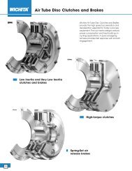
E Clutch ApplicationForm E 604 Coupling Arrangement – Dimensional Data Sizes 12 to 40DD 6 D 45ElementDrumElement HubRotorsealO 4DrumHubD 1 X D 7HRefer to component catalogpages for componentdetails.Shafts and keysby customerD 37 D 38Element & Hub C.G.C.G. Drum & HubEnglishlb⋅in@75psilbDimensions in inches12E475 11300 B3 150 1.50 2.50 1.50 2.75 10.25 3.75 8.00 3.75 3.20 4.12 1.25 18.00 1/4-18 2.7514E475 16000 B3 183 1.50 3.00 1.50 3.00 10.75 3.75 8.00 4.25 3.21 4.30 1.75 20.00 1/4-18 2.7516E475 21500 B3 237 1.75 3.50 1.75 3.25 12.00 4.25 8.00 5.00 3.72 4.70 3.50 22.00 3/8-18 2.7519E475 31500 B3 327 2.25 4.50 2.25 4.75 14.44 5.75 8.00 6.00 4.60 5.10 3.50 25.00 3/8-18 2.6821.5E475 40500 B3 383 2.25 4.50 2.75 4.75 14.44 5.75 8.00 6.00 4.75 5.20 3.50 29.50 3/8-18 2.6824E475 52000 B3 514 3.00 6.50 2.75 5.25 18.06 6.50 8.00 9.00 5.19 5.33 6.37 32.00 3/8-18 2.6827E475 67000 B3 580 2.75 5.25 2.75 5.50 16.56 6.50 8.00 7.50 5.30 6.21 4.87 35.00 3/8-18 2.5630E600 106000 C2 740 2.75 5.50 2.75 5.50 17.31 6.50 9.75 7.50 5.60 6.04 4.62 38.00 1/2-14 3.3134E600 137000 C2 947 3.00 6.00 3.00 6.00 20.31 8.00 9.75 9.00 6.90 7.07 6.12 42.00 1/2-14 3.3140E700 225000 C2 1592 3.75 7.00 3.75 7.00 22.75 9.00 10.75 10.00 8.13 7.50 7.12 48.00 1/2-14 3.75SizeM rTorqueRatingRotorsealSizeWeightMassMin. Max. Min. Max.Drum Hub BoreElement Hub BoreMin. Max. Min. Max.D D 1 D 6 D 7 D 37 D 38 D 45 H O 4 X12E475 1280 B3 68 38 64 38 70 260 95 203 95 81 105 32 457 1/4-18 7014E475 1810 B3 83 38 76 38 76 273 95 203 108 82 109 44 508 1/4-18 7016E475 2430 B3 107 44 89 44 83 305 108 203 127 94 119 89 559 3/8-18 7019E475 3560 B3 148 57 114 57 121 367 146 203 152 117 130 89 635 3/8-18 6821.5E475 4580 B3 173 57 114 70 121 367 146 203 152 121 132 89 749 3/8-18 6824E475 5880 B3 233 76 165 70 133 459 165 203 229 132 135 162 813 3/8-18 6827E475 7570 B3 263 70 133 70 140 421 165 203 191 135 158 124 889 3/8-18 6530E600 12000 C2 335 70 140 70 140 440 165 248 191 142 153 117 965 1/2-14 8434E600 15500 C2 429 76 152 76 152 516 203 248 229 175 180 155 1067 1/2-14 8440E700 25400 C2 721 95 178 95 178 578 229 273 254 207 191 181 1219 1/2-14 95SIN⋅m@ 5,2 barNotes: Refer to Rotorseal Section for mounting and dimensioninformation. Dynamic torque shown, static torque approximately25% greater. Torque in each application isdependent upon release spring force, air pressureand speed.kgDimensions in millimeters Total weight or mass with minimum hub bores.Rotorseal and hose not included. American National Pipe Thread Figures shown are with teflon or graphite slip linings.Multiply values by 1.5 for standard linings,and contact factory for possible need of reinforcedhousings.C-9Copyright Eaton Corporation, 1997, All rights reserved.
Form E 605E Clutch ApplicationCoupling Arrangement – Dimensional DataSizes Dual 12 to Dual 34DD 6 D 45DrumElementsRotorsealO 40 4DrumHub90 ° Adapter HubEnd view of shaft showingradial location of hole O 4 tokeyway.D 1 X D 7MHRefer to componentcatalog pages forcomponent detailsShafts and keys bycustomerD 37 D 38C.G.Element & Hub AdapterC.G.Drum & HubEnglishlb⋅in@75psilb Dimensions in inches12E475 22600 B3 253 1.50 2.50 2.50 3.75 15.25 6.38 14.00 3.75 3.20 6.31 1.25 18.00 1/4-18 2.5014E475 32000 B3 349 1.50 3.00 2.50 3.75 15.75 6.38 14.00 4.25 3.20 6.43 1.75 20.00 1/4-18 2.5016E475 43000 B3 457 1.75 3.50 1.50 3.00 16.50 4.25 14.00 5.00 3.88 7.25 2.50 22.00 5.25 3/8-18 4.8819E475 63000 C2 599 2.25 4.50 2.25 4.50 17.50 6.00 14.00 6.00 5.22 7.69 3.50 25.00 5.25 3/8-18 4.8121.5E475 81000 C2 670 2.25 4.50 2.25 4.50 17.50 6.00 14.00 6.00 5.40 7.50 3.50 29.50 5.25 3/8-18 4.8824E475 104000 C2 883 3.00 6.50 2.75 5.50 20.38 7.50 14.00 9.00 6.29 7.15 4.00 32.00 6.38 3/8-18 4.8827E475 134000 C2 1010 2.75 5.25 2.75 4.75 18.88 6.75 14.00 7.50 6.14 8.62 4.88 35.00 5.25 3/8-18 4.7530E600 212000 C2 1496 2.75 5.50 2.75 5.50 22.38 7.50 17.75 7.50 6.83 9.13 4.63 38.00 6.44 1/2-14 6.7234E600 274000 3/4 RH 1747 3.00 6.00 2.75 5.50 23.88 7.50 17.75 9.00 7.01 10.88 6.13 42.00 6.44 1/2-14 6.72Min. Max. Min. Max.SizeMrTorqueRotorsealWeightRating Size MassDrum Hub BoreAdapter HubBoreD D 1 D 6 D 7 D 37 D 38 D 45 H M O 4 XMin. Max. Min. Max.12E475 2550 B3 115 38 64 64 95 387 162 356 95 81 160 32 457 1/4-18 6414E475 3620 B3 158 38 76 64 95 400 162 356 108 81 163 44 508 1/4-18 6416E475 4860 B3 207 44 89 38 76 419 108 356 127 99 184 64 559 133 3/8-18 12419E475 7120 C2 271 57 114 57 114 445 152 356 152 133 195 89 635 133 3/8-18 12221.5E475 9150 C2 304 57 114 57 114 445 152 356 152 137 191 89 749 133 3/8-18 12424E475 11800 C2 400 76 165 70 140 518 191 356 229 160 182 102 813 162 3/8-18 12427E475 15100 C2 458 70 133 70 121 480 171 356 191 156 219 124 889 133 3/8-18 12130E600 24000 C2 678 70 140 70 140 568 191 451 191 173 232 118 965 164 1/2-14 17134E600 31000 3/4 RH 791 76 152 70 140 607 191 451 229 178 276 156 1067 164 1/2-14 171SIN⋅m5,2 barkg Dimensions in inchesNotes: Refer to Rotorseal Section for mounting and dimensioninformation. Dynamic torque shown, static torque approximately25% greater. Torque in each application isdependent upon release spring force, air pressureand speed. Total weight or mass with minimum hub bores.Rotorseal and hose not included. American National Pipe Thread Locate radial shaft hole just beyond element hub. Figures shown are with teflon or graphite slip linings.Multiply values by 1.5 for standard linings,and contact factory for possible need of reinforcedhousings.Copyright Eaton Corporation, 1997, All rights reserved.C-10
Form E 606E Clutch ApplicationBearing Mounted Arrangement – Dimensional DataSizes 12 to 40DD 6 D 45DrumElementEnd view of shaft showingradial location of hole O 4 tokeyway.Element HubRotorseal90 ° HO 4D 1O 4M0 4 DBearing Mounted Drum30HubJShafts and keys bycustomerEnglishlb⋅in@75psilbDimensions in inches11300 165 B3 1.50 2.19 10.81 4.75 8.00 1.25 2.63 18.00 3.875 1/4-1814E475 16000 210 B3 1.50 3.00 11.31 4.75 8.00 1.75 3.13 20.00 5.875 1/4-1816E475 21500 275 B3 1.75 3.50 12.44 5.25 8.00 2.50 3.88 22.00 5.875 3.16 3/8-1819E475 31500 390 B3 2.25 4.50 14.94 6.75 8.00 3.50 4.88 25.00 6.875 3.25 3/8-1821.5E475 40500 450 B3 2.25 4.50 14.94 6.75 8.00 3.50 4.88 29.50 6.875 3.19 3/8-1824E475 52000 650 B3 3.00 5.00 16.19 7.50 8.00 4.00 5.38 32.00 7.375 3.31 3/8-1827E475 67000 700 B3 2.75 5.25 17.19 7.50 8.00 4.88 6.38 35.00 8.375 3.31 3/8-1830E600 106000 900 C2 2.75 5.50 18.19 7.50 9.75 4.88 6.38 38.00 8.875 3.75 1/2-1434E600 137000 1160 C2 3.00 6.00 21.19 9.00 9.75 6.38 7.88 42.00 9.375 3.75 1/2-1440E700 225000 1920 C2 5.00 7.00 23.63 10.00 10.75 7.38 8.88 48.00 10.875 3.88 1/2-14SizeM rTorqueRatingWeightMassRotorsealSizeMin.Min.Bore RangeMax.Max.D D 1 D 6 D 30 D 45 H J MAX M O 412E475 1280 75 B3 38 56 275 121 203 32 67 457 98,4 1/4-1814E475 1810 95 B3 38 76 287 121 203 44 80 508 149,2 1/4-1816E475 2430 125 B3 44 89 316 133 203 64 99 559 149,2 80 3/8-1819E475 3560 177 B3 57 114 379 171 203 89 124 635 174,6 83 3/8-1821.5E475 4580 204 B3 57 114 379 171 203 89 124 749 174,6 81 3/8-1824E475 5880 294 B3 76 127 411 191 203 102 137 813 187,3 84 3/8-1827E475 7570 317 B3 70 133 437 191 203 124 162 889 212,7 84 3/8-1830E600 12000 408 C2 70 140 462 191 248 124 162 965 225,4 95 1/2-1434E600 15500 525 C2 76 152 538 229 248 162 200 1067 238,1 95 1/2-1440E700 25400 870 C2 127 178 600 254 273 187 226 1219 276,2 99 1/2-14SIN⋅m@ 5,2 barkgDimensions in millimetersNotes: Refer to Rotorseal Section for mounting and dimensioninformation. Dynamic torque shown, static torque approximately25% greater. Torque in each application isdependent upon release spring force, air pressureand speed. Total weight or mass with minimum hub bores.Rotorseal and hose not included. Locate radial shaft hole just beyond element hub. American National Pipe Thread Figures shown are with slip linings. Multiply valuesby 1.5 for standard linings, and contact factory forpossible need of reinforced housings.C-11Copyright Eaton Corporation, 1997, All rights reserved.
Form E 607E Clutch ApplicationBearing Mounted Arrangement – Dimensional DataSizes Dual 12 to Dual 34DD 6 D 45DrumElementDual AdapterRingRotorseal 90 °O 4D 24O 4O 4D 30Bearing Mounted DrumHubEnd view of shaft showingradial location of hole O 4 tokeyway.JHShaft and keys bycustomerEnglishlb⋅in@75psilbDimensions in inches12E475 22600 270 B3 1.50 2.19 16.63 14.00 1.47 1.25 2.63 18.00 3.875 1/4-1814E475 32000 450 B3 1.50 3.38 17.13 14.00 1.47 1.75 3.13 20.00 5.875 1/4-1816E475 43000 560 B3 1.75 3.50 17.88 14.00 1.47 2.50 3.88 22.00 5.875 3/8-1819E475 63000 690 C2 2.25 4.75 18.88 14.00 1.50 3.50 4.88 25.00 6.875 3/8-1821.5E475 81000 840 C2 2.75 4.75 18.88 14.00 1.50 3.50 4.88 29.50 6.875 3/8-1824E475 104000 1080 C2 2.75 5.00 19.38 14.00 1.50 4.00 5.38 32.00 7.375 3/8-1827E475 134000 1130 C2 2.75 6.00 20.38 14.00 1.50 4.88 6.38 35.00 8.375 3/8-1830E475 212000 1660 C2 2.75 7.00 24.13 17.75 1.88 4.88 6.38 38.00 8.875 1/2-1434E475 274000 1960 3/4 RH 3.00 7.00 25.63 17.75 1.88 6.38 7.88 42.00 9.375 1/2-14SizeM rTorqueRatingWeightMassRotorsealSizeMin.Min.Bore RangeMax.Max.D D 6 D 24 D 30 D 45 H J MAX O 412E475 2550 122 B3 38 56 422 356 37 32 67 457 98,4 1/4-1814E475 3620 204 B3 38 86 435 356 37 44 80 508 149,2 1/4-1816E475 4860 254 B3 44 89 454 356 37 64 99 559 149,2 3/8-1819E475 7120 313 C2 57 121 480 356 38 89 124 635 174,6 3/8-1821.5E475 9150 381 C2 70 121 480 356 38 89 124 749 174,6 3/8-1824E475 11800 489 C2 70 127 492 356 38 102 137 813 187,3 3/8-1827E475 15100 512 C2 70 152 518 356 38 124 162 889 212,7 3/8-1830E475 24000 752 C2 70 178 613 451 48 124 162 965 225,4 1/2-1434E475 31000 888 3/4 RH 76 178 651 451 48 162 200 1067 238,1 1/2-14SIN⋅m@ 5,2 barkgDimensions in millimetersNotes: Refer to Rotorseal Section for mounting and dimensioninformation. Dynamic torque shown, static torque approximately25% greater. Torque in each application isdependent upon release spring force, air pressureand speed.Copyright Eaton Corporation, 1997, All rights reserved. Total weight or mass with minimum hub bores.Rotorseal and hose not included. American National Pipe Thread Figures shown are with slip linings. Multiply valuesby 1.5 for standard linings, and contact factory forpossible need of reinforced housings.C-12
E Brake ApplicationForm E 608 Air-Cooled Arrangement – Dimensional Data Sizes 12 to 40DD 6DrumElementAdapter RingDrum HubO 4D 7H minP minD 36Refer to component catalogpages for componentdetailsShaft and key bycustomerC.G. Drum & HubReaction MemberEnglishlb⋅in@75psilbDimensions in inches12E475 11300 151 1.50 2.50 9.81 8.56 3.75 3.79 18.50 1/4-18 9.5014E475 16000 186 1.50 3.00 10.31 8.56 4.25 3.86 20.50 1/4-18 10.5016E475 21500 238 1.75 3.50 11.06 8.56 5.00 3.92 22.50 3/8-18 11.5019E475 31500 306 2.25 4.50 12.00 8.50 6.00 3.59 25.50 3/8-18 13.0021.5E475 40500 379 2.25 4.50 12.06 8.56 6.00 3.47 30.25 3/8-18 15.5024E475 52000 494 3.00 6.50 15.75 8.63 9.00 3.42 32.75 3/8-18 16.7527E475 67000 573 2.75 5.25 13.50 8.63 7.50 3.39 35.75 3/8-18 18.2530E600 106000 794 2.75 5.50 15.03 10.41 7.50 3.81 38.75 1/2-14 19.7534E600 137000 1010 3.00 6.00 16.53 10.41 9.00 3.83 42.75 1/2-14 21.7540E700 225000 1660 3.75 7.00 18.53 11.41 10.00 3.98 48.75 1/2-14 24.75SizeM rTorqueRatingWeightMassMin.Min.Bore RangeMax.Max.D D 6 D 7 D 38 H O 4 P12E475 1280 68 38 64 249 217 95 96 470 1/4-18 24114E475 1810 84 38 76 262 217 108 98 521 1/4-18 26716E475 2430 108 44 89 281 217 127 100 572 3/8-18 29219E475 3560 139 57 114 305 216 152 91 648 3/8-18 33021.5E475 4580 172 57 114 306 217 152 88 768 3/8-18 39424E475 5880 224 76 165 400 219 229 87 832 3/8-18 42527E475 7570 260 70 133 343 219 191 86 908 3/8-18 46430E600 12000 360 70 140 382 264 191 97 984 1/2-14 50234E600 15500 458 76 152 420 264 229 97 1086 1/2-14 55240E700 25400 752 95 178 471 290 254 101 1238 1/2-14 629SIN⋅m@ 5,2 barkgDimensions in millimetersNotes: Dynamic torque shown, static torque approximately25% greater. Torque in each application isdependent upon release spring force, air pressureand speed. Total weight or mass with minimum hub bores. Maximum length with drum hub reverse mounted. American National Pipe Thread Figures shown are with slip linings. Multiply valuesby 1.5 for standard linings, and contact factory forpossible need of reinforced housings.C-13Copyright Eaton Corporation, 1997, All rights reserved.
Form E 609E Brake ApplicationAir-Cooled Arrangement – Dimensional DataSizes Dual 12 to Dual 34DD 6DrumElementsDrum Hub O 4O 4D 7P minD 36HminDual AdapterRingRefer to component catalogpages for component detailsShaft and key bycustomerC.G. Drum & HubEnglishlb⋅in@75 psilbDimensions in inches12E475 22600 253 1.50 2.50 15.25 14.00 3.75 3.52 18.50 1/4-18 9.5014E475 32000 349 1.50 3.00 15.75 14.00 4.25 3.81 20.50 1/4-18 10.5016E475 43000 429 1.75 3.50 16.50 14.00 5.00 4.35 22.50 3/8-18 11.5019E475 63000 551 2.25 4.50 17.50 14.00 6.00 5.00 25.50 3/8-18 13.0021.5E475 81000 608 2.25 4.50 17.50 14.00 6.00 5.02 30.25 3/8-18 15.5024E475 104000 767 3.00 6.50 20.38 14.00 9.00 5.12 32.75 3/8-18 16.7527E475 134000 934 2.75 5.25 18.88 14.00 7.50 6.01 35.75 3/8-18 18.2530E600 212000 1363 2.75 5.50 22.38 17.75 7.50 6.35 38.75 1/2-14 19.7534E600 274000 1622 3.00 6.00 23.88 17.75 9.00 7.17 42.75 1/2-14 21.7540E700 450000 2788 3.75 7.00 27.13 20.00 10.00 7.71 48.75 1/2-14 24.75SizeMrTorqueRatingWeightMassMin.Min.Bore RangeMax.Max.D D 6 D 7 D 38 H O 4 P12E475 2550 115 38 64 387 356 95 89 470 1/4-18 24114E475 3620 158 38 76 400 356 108 97 521 1/4-18 26716E475 4860 194 44 89 419 356 127 110 572 3/8-18 29219E475 7120 250 57 114 445 356 152 127 648 3/8-18 33021.5E475 9150 275 57 114 445 356 152 128 768 3/8-18 39424E475 11800 347 76 165 518 356 229 130 832 3/8-18 42527E475 15100 423 70 133 479 356 191 153 908 3/8-18 46430E600 24000 617 70 140 568 451 191 161 984 1/2-14 50234E600 31000 735 76 152 606 451 229 182 1086 1/2-14 55240E700 50900 1263 95 178 689 508 254 196 1238 1/2-14 629SI N⋅m@ 5,2 barkgDimensions in millimetersNotes: Dynamic torque shown, static torque approximately25% greater. Torque in each application isdependent upon release spring force, air pressureand speed. Total weight or mass with minimum hub bores. Maximum length with drum hub reverse mounted. American National Pipe Thread Figures shown are with slip linings. Multiply valuesby 1.5 for standard linings, and contact factory forpossible need of reinforced housings.Copyright Eaton Corporation, 1997, All rights reserved.C-14
E Brake ApplicationForm E 610 Water cooled Arrangement – Dimensional Data – Sizes 12 to 34Water-cooledDrumElementD 6DElement HubRotorsealO 4MD 1HRefer to component catalogpages for component detailsPShaft and key bycustomerEnglishlb⋅in@75psilbDimensions in inches12E475 11300 B3 149 1.50 2.75 6.47 3.75 5.50 21.13 1.22 1/4-18 12.5014E475 16000 B3 165 1.50 3.00 6.47 3.75 5.50 23.13 1.22 1/4-18 13.5016E475 21500 B3 234 1.75 3.25 6.97 4.25 5.50 28.00 1.22 3/8-18 16.0019E475 31500 B3 280 2.25 4.75 8.94 5.75 5.50 28.13 1.19 3/8-18 16.0021.5E475 40500 B3 324 2.75 4.75 8.44 5.75 5.50 30.63 1.19 3/8-18 17.2524E475 52000 B3 391 2.75 5.25 9.19 6.50 5.50 33.13 1.19 3/8-18 18.5027E475 67000 B3 443 2.75 5.50 9.19 6.50 5.50 36.13 1.19 3/8-18 20.0030E600 106000 C2 552 2.75 5.50 9.94 6.50 7.00 39.13 1.56 1/2-14 21.5034E600 137000 C2 655 3.00 6.00 11.44 8.00 7.00 43.13 1.56 1/2-14 23.50SizeM rTorqueRatingRotosealSizeWeightMassMIn.Min.Bore RangeMax.Max.D D 1 D 6 H M O 4 P12E475 1280 B3 67 38 70 164 95 140 537 31 1/4-18 31814E475 1810 B3 75 38 76 164 95 140 587 31 1/4-18 34316E475 2430 B3 106 44 83 177 108 140 711 31 3/8-18 40619E475 3560 B3 127 57 121 227 146 140 714 30 3/8-18 40621.5E475 4580 B3 147 70 121 214 146 140 778 30 3/8-18 43824E475 5880 B3 177 70 133 233 165 140 841 30 3/8-18 47027E475 7570 B3 201 70 140 233 165 140 918 30 3/8-18 50830E600 12000 C2 250 70 140 252 165 178 994 40 1/2-14 54634E600 15500 C2 297 76 152 291 203 178 1095 40 1/2-14 597SIN⋅m@ 5,2 barkgDimensions in millimetersNotes: Refer to Rotorseal Section for mounting and dimensioninformation. Dynamic torque shown, static torque approximately25% greater. Torque in each application isdependent upon release spring force, air pressureand speed. Total weight or mass with minimum hub bores.Rotorseal and hose not included. American National Pipe Thread Figures shown are with teflon or graphite slip linings.Multiply values by 1.5 for standard linings,and contact factory for possible need of reinforcedhousings.C-15Copyright Eaton Corporation, 1997, All rights reserved.
<strong>VE</strong> ElementForm <strong>VE</strong> 602 Dimensional Data Sizes 19 to 27D 2WV<strong>VE</strong> Elements can be furnished in the clutch and brake applications shown forthe E elements.D 24D 25QO 4H 2D 46 H 13H 6LGEnglishlb⋅in@75psiDimensions in inches19<strong>VE</strong>475 143215 25500 5.69 1.25 0.19 2.72 9.625 10.750 18.91 11.81 8 0.50 3/8-18 22.50 0.44 12 4.6924<strong>VE</strong>475 143216 45200 5.69 1.25 0.25 2.75 14.250 15.750 23.91 17.25 8 0.75 3/8-18 22.50 0.44 14 4.6927<strong>VE</strong>475 143334 58500 5.69 1.25 0.27 2.75 16.750 18.250 26.91 19.73 10 0.75 3/8-18 18.00 0.44 16 4.75SizePartNumberM rTorqueRatingNo. Dia.D 2 D 24 D 25 D 46 G H 2 H 6 H 13 LQ 4 Q VNo.WidthNo. Dia. No. Width19<strong>VE</strong>475 143215 2880 145 32 5 69 244,5 273,1 480 300 8 13 3/8-18 22,50 11 12 11924<strong>VE</strong>475 143216 5110 145 32 6 70 362,0 400,1 607 438 8 19 3/8-18 22,50 11 14 11927<strong>VE</strong>475 143334 6610 145 32 7 70 425,5 463,6 684 501 10 19 3/8-18 18,00 11 16 121SIN⋅m@ 5,2 barDimensions in millimetersLEnglishlb⋅in@75psirpm psi/rpm 2 lb⋅ft 2 lb in 2 inches in 3 in19<strong>VE</strong>475 143215 25500 1100 3.3 E-06 20 58 230 0.43 0.25 70 19.1324<strong>VE</strong>475 143216 45200 875 5.6 E-06 61 77 295 0.37 0.18 100 24.1927<strong>VE</strong>475 143334 58500 775 5.9 E-06 75 90 333 0.37 0.25 110 27.25SizePartNumberM rTorqueRatingMaximumSpeedC sCentrifugalGainWk 2JWeightMassFrictionAreaNewWornLining Thickness19<strong>VE</strong>475 143215 2880 1100 0,2 E-06 0,84 26 1484 11 6 1,1 48624<strong>VE</strong>475 143216 5110 875 0,4 E-06 2,56 35 1903 9 5 1,6 61427<strong>VE</strong>475 143334 6610 775 0,4 E-06 3,15 41 2148 9 6 1,8 692SI N⋅m@ 5,2 barNewWornAirTubeCavityMaximumDrumDiameterrpm bar/rpm 2 kg⋅m 2 kg cm 2 millimeters dm 3 mmNotes: Refers to basic part number only. When ordering,the release spring force and type of friction liningsmust be specified. Dynamic torque shown, static torque approximately25% greater. Torque in each application isdependent upon release spring force, air pressureand speed. Tolerances for sizes:12 thru 27+0.010/-0.000 in (+0,25/-0,00 mm)30 thru 40+0.005/-0.000 in (+0,13/-0,00 mm) American National Pipe Thread Drum contact with worn shoes. Figures shown are with teflon or graphite slip linings.Multiply values by 1.5 for standard linings,and contact factory for possible need of reinforcedhousings. Refer to page C-42 for maximum idle RPM.Copyright Eaton Corporation, 1997, All rights reserved.C-16
E and <strong>VE</strong> Mounting ComponentsForm E 611 Element Hubs – Dimensional and Technical Data – Sizes 12 to 40H 14D 7D 29D 42H 11Through ortapped holesEnglishThruHolesTappedHoleslb lb⋅ft 2 Dimensions in inches12E475 402241 402242 20 0.8 4.75 1.13 0.63 7.75 4.3814E475 402244 402245 22 1 4.75 1.13 0.63 9.50 5.0016E475 402247 402248 36 3 5.25 1.13 0.75 11.63 5.5019E475 401476 401477 74 6 6.75 1.19 0.63 14.56 7.5021.5E475 401478 401479 86 12 6.75 1.19 0.63 17.00 7.5024E475 401480 401481 122 19 7.50 1.19 0.63 19.63 8.5027E475 401482 401483 145 34 7.50 1.19 0.63 22.63 9.0030E600 401484 401485 138 38 7.50 1.22 0.56 24.50 9.0034E600 401486 401487 183 58 9.00 1.22 0.56 28.50 9.5040E700 402250 402251 263 98 10.00 1.22 0.56 33.50 11.0019<strong>VE</strong>475 402247 402248 36 3 5.25 1.13 0.75 11.63 5.5024<strong>VE</strong>475 401478 401479 86 12 6.75 1.19 0.63 17.00 7.5027<strong>VE</strong>475 401480 401481 122 19 7.50 1.19 0.63 19.63 8.50SizePart NumberWeightWk 2 D 7 D 29 D 42 H 11 H 14MassJ12E475 402241 402242 9,1 0,03 121 29 16 197 11114E475 402244 402245 10 0,04 121 29 16 241 12716E475 402247 402248 16 0,12 133 29 19 295 14019E475 401476 401477 34 0,24 171 30 16 370 19121.5E475 401478 401479 39 0,48 171 30 16 432 19124E475 401480 401481 55 0,81 191 30 16 498 21627E475 401482 401483 66 1,42 191 30 16 575 22930E600 401484 401485 63 1,60 191 31 14 622 22934E600 401486 401487 83 2,45 229 31 14 724 24140E700 402250 402251 119 4,12 254 31 14 851 27919<strong>VE</strong>475 402247 402248 16 0,12 133 29 19 295 14024<strong>VE</strong>475 401478 401479 39 0,48 171 30 16 432 19127<strong>VE</strong>475 401480 401481 55 0,81 191 30 16 498 216SIThruHolesTappedHoleskg kg⋅m 2 Dimensions in millimetersNotes: Based upon minimum bores.C-17Copyright Eaton Corporation, 1997, All rights reserved.
E and <strong>VE</strong> Mounting ComponentsForm E 614 Drum Hubs – Dimensional and Technical Data – Size 12 to 40D 7Through ortapped holesD 42 D 29H H 11 14EnglishThruHolesTappedHoleslb lb⋅ft 2 Dimensions in inches12E475 404351 402262 13 0.3 3.75 1.125 0.63 6.25 4.0014E475 404352 402264 25 1.0 4.25 1.125 0.63 8.25 5.0016E475 404353 402266 38 1.5 5.00 1.125 0.63 9.25 6.0019E475 404354 402268 64 5 6.00 1.125 0.63 11.50 7.0021.5E475 404355 402270 71 6 6.00 1.125 0.63 13.50 7.0024E475 404638 133 18 9.00 1.125 0.63 15.00 9.5027E475 403194 402274 121 15 7.50 1.125 0.75 15.00 8.5030E600 404357 402276 162 35 7.50 1.125 0.75 20.00 9.0034E600 404358 402278 214 59 9.00 1.125 0.75 23.00 9.5040E700 404359 402280 330 139 10.00 1.125 0.75 28.50 11.0019<strong>VE</strong>475 404353 402266 38 1.5 5.00 1.125 0.63 9.25 6.0024<strong>VE</strong>475 404355 402270 71 6 6.00 1.125 0.63 13.50 7.0027<strong>VE</strong>475 404356 402272 72 9 6.50 1.125 0.63 15.00 7.50SizePart NumberWeightWk 2 D 7 D 29 D 42 H 11 H 14MassJ12E475 404351 402262 5,9 0,01 95 28,6 15,9 159 10214E475 404352 402264 11 0,04 108 28,6 15,9 210 12716E475 404353 402266 17 0,06 127 28,6 15,9 235 15219E475 404354 402268 29 0,19 152 28,6 15,9 292 17821.5E475 404355 402270 32 0,26 152 28,6 15,9 343 17824E475 404638 60 0,74 229 28,6 15,9 381 24127E475 403194 402274 55 0,62 191 28,6 19,1 381 21630E600 404357 402276 73 1,47 191 28,6 19,1 508 22934E600 404358 402278 97 2,48 229 28,6 19,1 584 24140E700 404359 402280 149 5,84 254 28,6 19,1 724 27919<strong>VE</strong>475 404353 402266 17 0,06 127 28,6 15,9 235 15224<strong>VE</strong>475 404355 402270 32 0,25 152 28,6 15,9 343 17827<strong>VE</strong>475 404356 402272 33 0,38 165 28,6 15,9 381 191SIThruHolesTappedHoleskg kg⋅m 2 Dimensions in millimetersNotes: Based upon minimum bores.Copyright Eaton Corporation, 1997, All rights reserved.C-18
Form E 618E and <strong>VE</strong> Mounting ComponentsDual Adapter Ring Hubs – Dimensional and Technical DataSizes 16 to 34H 14D 7D 29D 42H 11Through ortapped holesEnglishThruHolesTappedHoleslb lb⋅ft 2 Dimensions in inches16E475 402290 402291 28 1 4.25 1.13 0.63 8.25 5.0019E475 402292 402293 48 3 6.00 1.13 0.63 11.00 7.0021.5E475 402294 402295 62 5 6.00 1.13 0.63 12.50 7.0024E475 402296 402297 116 10 7.50 1.13 0.75 15.50 9.0027E475 401447 401448 72 16 6.75 1.13 0.75 17.50 7.5030E600 402298 402299 133 26 7.50 1.13 0.75 19.00 9.0034E600 402300 402301 125 51 7.50 1.13 0.75 22.88 9.0019<strong>VE</strong>475 402290 402291 28 1 4.25 1.13 0.63 8.25 5.0024<strong>VE</strong>475 402294 402297 62 5 6.00 1.13 0.63 12.50 7.0027<strong>VE</strong>475 402296 402297 116 10 7.50 1.13 0.75 17.50 7.50Weight WkSizePart NumberMassJD 7 D 29 D 42 H 11 H 1416E475 402290 402291 13 0,04 108 28,6 15,9 210 12719E475 402292 402293 22 0,11 152 28,6 15,9 279 17821.5E475 402294 402295 28 0,21 152 28,6 15,9 318 17824E475 402296 402297 53 0,41 191 28,6 19,1 394 22927E475 401447 401448 32 0,67 171 28,6 19,1 445 19130E600 402298 402299 60 1,09 191 28,6 19,1 483 22934E600 402300 402301 56 2,14 191 28,6 19,1 581 22919<strong>VE</strong>475 402290 402291 13 0,04 108 28,6 16,0 209,6 127,024<strong>VE</strong>475 402294 402295 28 0,21 152 28,6 16,0 317,5 177,827<strong>VE</strong>475 402296 402297 53 0,42 191 28,6 19,1 444,5 190,5SIThruHolesTappedHoleskg kg⋅m 2 Dimensions in millimetersNotes: Based upon minimum bores.C-19Copyright Eaton Corporation, 1997, All rights reserved.
E and <strong>VE</strong> Mounting ComponentsForm E 615 Ventilated Drums – Dimensional and Technical Data – Sizes 12 to 40LH 9HH 1D 6D 31J 1EnglishDimensions in inchesThruHolesTappedHoleslb lb⋅ft 2 inThruHolesTappedHoleslb lb⋅ft 2 in12E475 0.75 18.00 12.00 5.063 4.187 6 0.53 1/2-13 510363 510536 95 30 8.00 401313 N/A 155 45 14.0014E475 0.75 20.00 14.00 7.250 6.250 6 0.53 1/2-13 510079 510417 105 45 8.00 401315 402033 200 70 14.0016E475 0.75 22.00 16.00 7.750 6.250 6 0.78 3/4-10 510364 510453 120 60 8.00 401317 402034 235 155 14.0019E475 0.75 25.00 19.00 10.000 8.250 8 0.78 3/4-10 412715 413328 140 85 8.00 401319 402035 275 190 14.0021.5E475 0.75 29.50 21.50 12.000 10.750 6 0.78 3/4-10 510365 510537 170 140 8.00 401321 402036 300 285 14.0024E475 0.75 32.00 24.00 13.500 12.125 8 0.78 3/4-10 401303 401534 195 220 8.00 401323 402037 315 330 14.0027E475 0.75 35.00 27.00 13.500 12.125 8 0.78 3/4-10 510077 510418 240 275 8.00 401325 402038 430 570 14.0030E600 1.00 38.00 30.00 18.500 16.750 10 0.78 3/4-10 401307 401536 315 615 9.75 401327 402039 600 960 17.7534E600 1.00 42.00 34.00 21.500 19.500 14 0.78 3/4-10 401309 401537 395 730 9.75 401329 402040 645 1300 17.7540E700 1.00 48.00 40.00 27.000 25.000 18 0.78 3/4-10 401712 401538 480 1210 10.75 401331 402041 775 2170 20.0019<strong>VE</strong>475 0.75 25.00 19.00 10.000 8.250 8 0.78 3/4-10 412715 413328 140 85 8.00 401319 402035 275 190 14.0024<strong>VE</strong>475 0.75 32.00 24.00 13.500 12.125 8 0.78 3/4-10 401303 401534 195 220 8.00 401323 402037 315 330 14.002 227<strong>VE</strong>475 0.75 35.00 27.00 13.500 12.125 8 0.78 3/4-10 510077 510418 240 275 8.00 401325 402038 430 570 14.00 No. Thru Tapped Part Number Weight Wk D 6 Part Number Weight Wk D 6Size D 31 H H 1 H 9 J 9 L Single Element Drum Dual Element DrumNo. Thru Tapped Part Number Mass J D 6 Part Number Mass J D 612E475 19 457 305 128,6 106,3 6 13 1/2-13 510363 510536 43 1,26 203 401313 N/A 70 1,89 35614E475 19 508 356 184,2 158,8 6 13 1/2-13 510079 510417 48 1,89 203 401315 402033 91 2,94 35616E475 19 559 406 196,9 158,8 6 20 3/4-10 510364 510453 54 2,52 203 401317 402034 106 6,51 35619E475 19 635 483 254,0 209,6 8 20 3/4-10 412715 413328 63 3,57 203 401319 402035 125 7,98 35621.5E475 19 749 546 304,8 273,1 6 20 3/4-10 510365 510537 77 5,88 203 401321 402036 136 11,97 35624E475 19 813 610 342,9 308,0 8 20 3/4-10 401303 401534 88 9,24 203 401323 402037 143 13,86 35627E475 19 889 686 342,9 308,0 8 20 3/4-10 510077 510418 109 11,55 203 401325 402038 195 23,94 35630E600 25 965 762 469,9 425,5 10 20 3/4-10 401307 401536 143 25,83 248 401327 402039 272 40,32 45134E600 25 1067 864 546,1 495,3 14 20 3/4-10 401309 401537 179 30,66 248 401329 402040 292 54,60 45140E700 25 1219 1016 685,8 635,0 18 20 3/4-10 401712 401538 217 50,82 273 401331 402041 351 91,14 50819<strong>VE</strong>475 19 635 483 254,0 209,6 8 20 3/4-10 412715 413328 63 3,57 203 401319 402035 125 7,98 35624<strong>VE</strong>475 19 813 610 342,9 308,0 8 20 3/4-10 401303 401534 88 9,24 203 401323 402037 143 13,86 35627<strong>VE</strong>475 19 889 686 342,9 308,0 8 20 3/4-10 510077 510418 109 11,55 203 401325 402038 195 23,94 356SIDimensions in millimetersThruHolesTappedHoleskg kg⋅m 2 mmThruHolesTappedHoleskg kg⋅m 2 mmNotes: Tolerance +0.005/-0.000 in (0,13/-0,00 mm) American National Standard for Unified ScrewThreads.Copyright Eaton Corporation, 1997, All rights reserved.C-20
E and <strong>VE</strong> Mounting ComponentsForm E 612 Adapter Rings – Dimensional and Technical Data – Sizes 12 to 40D 9D 11LH 9H 5 H 11 JEnglish lb lb⋅ft 2 Dimensions in inches12E475 12117 21 2 3.38 .19 6.25 7.00 5.50 8.120 10 3/8-16 0.7514E475 12118 25 3 3.38 .19 8.00 8.75 7.13 9.745 12 3/8-16 0.6316E475 12119 37 6 3.38 .19 9.75 10.75 9.13 11.745 8 1/2-13 0.8819E475 12120 53 14 3.38 .25 12.75 13.75 11.63 14.745 10 1/2-13 1.0021.5E475 12121 82 28 3.44 .25 14.25 15.75 13.75 17.120 8 3/4-10 1.1224E475 12122 102 50 3.50 .25 16.75 18.25 16.00 19.745 10 3/4-10 1.1227E475 12123 138 80 3.50 .25 19.75 21.25 18.00 22.620 12 3/4-10 1.1230E600 12124 192 145 4.31 .31 21.50 23.00 20.00 24.870 14 3/4-10 1.1234E600 12125 246 240 4.31 .31 25.50 27.00 24.00 28.870 16 3/4-10 1.2540E700 12126 331 445 4.88 .31 30.50 32.00 29.00 33.745 18 3/4-10 1.5019<strong>VE</strong>475 12120 37 6 3.38 .25 9.75 10.75 9.13 11.745 8 1/2-13 0.8824<strong>VE</strong>475 12121 82 28 3.44 .25 14.25 15.75 13.75 17.120 8 3/4-10 1.1227<strong>VE</strong>475 12122 102 50 3.50 .25 16.75 18.25 16.00 19.475 10 3/4-10 1.12SizePartNumberWeightMassWk 2Notes: Tolerance +0.000/-0.005 in (+0,00/-0,13 mm)JD 9 D 11 H 5 H 9 H 11 JNo. Size DepthLNo. Size Depth12E475 12117 9,5 0,07 86 4,83 159 178 140 206,2 10 3/8-16 1914E475 12118 11 0,11 86 4,83 203 222 181 247,5 12 3/8-16 1616E475 12119 17 0,26 86 4,83 248 273 232 298,3 8 1/2-13 2219E475 12120 24 0,57 86 6,35 324 349 295 374,5 10 1/2-13 2521.5E475 12121 37 1,19 87 6,35 362 400 349 434,8 8 3/4-10 2824E475 12122 46 2,10 89 6,35 425 464 406 501,5 10 3/4-10 2827E475 12123 63 3,37 89 6,35 502 540 457 574,5 12 3/4-10 2830E600 12124 87 6,09 109 7,87 546 584 508 631,7 14 3/4-10 2834E600 12125 111 10,08 109 7,87 648 686 610 733,3 16 3/4-10 3240E700 12126 150 18,69 124 7,87 775 813 737 857,1 18 3/4-10 3819<strong>VE</strong>475 12120 17 0,26 86 6,35 248 273 232 298,3 8 1/2-13 2224<strong>VE</strong>475 12121 37 1,19 87 6,35 362 400 349 434,8 8 3/4-10 2827<strong>VE</strong>475 12122 46 2,10 89 6,35 425 464 406 494,7 10 3/4-10 28SI kg kg⋅m 2 Dimensions in millimeters American National Standard for Unified ScrewThreads.C-21Copyright Eaton Corporation, 1997, All rights reserved.
E and <strong>VE</strong> Mounting ComponentsForm E 613 Dual Adapter Rings – Dimensional and Technical Data – Sizes 12 to 34For sizes 12 and 14 onlyDDD 3J 1H 11J 1 H 11English lb lb⋅ft 2 Dimensions in inches12E475 400234 38 2 6.38 N/A N/A 7.88 N/A N/A14E475 400476 64 5 6.38 N/A N/A 9.50 N/A N/A16E475 012135 72 10 6.25 0.50 6.75 11.63 5.500 8 0.7819E475 012208 106 30 6.38 0.50 9.50 14.63 8.000 10 0.7821.5E475 012098 116 40 6.38 0.63 11.00 17.13 9.625 6 0.7824E475 012209 187 90 6.38 0.63 13.50 19.62 11.500 8 1.0327E475 012210 234 145 6.38 0.63 16.00 22.63 14.625 8 0.7830E600 012211 353 250 8.13 0.75 17.00 24.50 15.000 12 1.0334E600 012212 453 445 8.13 0.75 21.00 28.50 19.000 12 1.03SizePartNumberWeightMassWk 2JNo Dia.D D 31 H 9 H 11 J 1 L12E475 400234 17 0,91 162 N/A N/A 200 N/A N/A14E475 400476 29 2,27 162 N/A N/A 241 N/A N/A16E475 012135 33 4,53 159 13 171 295 140 8 2019E475 012208 48 13,59 162 13 241 372 203 10 2021.5E475 012098 53 18,12 162 16 279 435 244 6 2024E475 012209 85 40,77 162 16 343 498 292 8 2627E475 012210 106 65,69 162 16 406 575 371 8 2030E600 012211 160 113,3 207 19 432 622 381 12 2634E600 012212 205 201,6 206 19 533 724 483 12 26SI kg kg⋅m 2 Dimensions in millimetersNoDia.Notes: Based upon minimum bores. Tolerance +0.005/-0.000 in (+0,13/-0,00 mm) Adapter ring bored and keyseated for shaft mounting.Bore 2.75 in (70 mm) minimum, 3.75 in (95mm) maximum.Copyright Eaton Corporation, 1997, All rights reserved.C-22
E Mounting ComponentsForm E 617 Water-Cooled Drums – Dimensional and Technical Data – Sizes 12 to 24LDD 49D 48DPHH 4Water outlet portWater inletD 50 portD 52D 51English lb in 3 Dimensions in inches12E475 403111 104 210 5.50 1.00 3.50 6.125 4.00 15.75 21.13 17.25 4 0.66 12.5014E475 403113 111 240 5.50 1.00 3.50 7.125 4.00 17.75 23.13 19.25 4 0.66 13.5016E475 402456 156 650 5.50 1.00 3.50 9.500 4.00 22.50 28.00 24.00 4 0.66 16.0019E475 402593 153 320 5.50 1.00 3.50 9.125 5.00 22.75 28.13 24.25 4 0.78 16.0021.5E475 403115 178 350 5.50 1.00 3.50 9.875 6.00 25.25 30.63 26.75 4 0.78 17.2524E475 403117 202 390 5.50 1.00 3.50 11.125 6.00 27.75 33.13 29.25 4 0.78 18.5027E475 403119 223 430 5.50 1.00 3.50 12.625 6.00 30.75 36.13 32.25 4 0.78 20.0030E600 402876 289 730 7.00 1.25 4.50 13.625 7.00 33.75 39.13 35.25 4 1.06 21.5034E600 403121 316 820 7.00 1.25 4.50 15.625 7.00 37.75 43.13 39.25 4 1.06 23.50No.. DiaPartWeight WaterSize NumberCavity D D 48 D 49 D 50 D 51 D 52 H H 4 LPMass VolumeNo.. Dia12E475 403111 47 3,44 140 25 89 155,6 102 400 537 438 4 17 31814E475 403113 50 3,94 140 25 89 181,0 102 451 587 489 4 17 34316E475 402456 71 10,7 140 25 89 241,3 102 572 711 610 4 17 40619E475 402593 69 5,2 140 25 89 231,8 127 578 714 616 4 20 40621.5E475 403115 81 5,7 140 25 89 250,8 152 641 778 679 4 20 43824E475 403117 92 6,4 140 25 89 282,6 152 705 841 743 4 20 47027E475 403119 101 7,1 140 25 89 320,7 152 781 918 819 4 20 50830E600 402876 131 12,0 178 32 114 346,1 178 857 994 895 4 27 54634E600 403121 143 13,4 178 32 114 396,9 178 959 1095 997 4 27 597SI kg dm 3 Dimensions in millimetersNotes: 1 1/4 - 11 1/2 American National Pipe Thread. Toinsure a water-filled cavity, it is important that thewater inlet be located at 6 o’clock and the outlet at12 o’clock.C-23Copyright Eaton Corporation, 1997, All rights reserved.