W01-358-2132 Datasheet - MRO Stop
W01-358-2132 Datasheet - MRO Stop
W01-358-2132 Datasheet - MRO Stop

You also want an ePaper? Increase the reach of your titles
YUMPU automatically turns print PDFs into web optimized ePapers that Google loves.
CRIMPED BEAD PLATEMOUNTING HARDWARECRIMPED BEAD PLATE AIR SPRINGS Use the blindnuts for attachment. This is accomplished by bringing bolts(two or four depending upon air spring size) through the3/8-16 UNCBlind Nut,5/8" Deepcustomer supplied mountIng plate and tightening into theblind nut. If this bolt is too long, it may fracture the bottomout of the blind nut.To Air Supply5/8"5/8"Customer SuppliesMounting PlatesBolts & WashersTightening Torqueon the blind nut: 15 to 20 ft.-lbs.STUD ADAPTER1/2-13 UNC Thread1.35If a protruding bolt rather than a blind nut is preferred toattach the air spring, a STUD ADAPTER is available fromFirestone:3/8-16 UNC Thread1.35Customer SuppliesMounting PlatesNuts & WashersTANK VALVE One method for inflating air springs(primarily used in Airmount isolator applications) is witha tank valve: An air hose chuck is used (as inflating atire with an air line). Care must be taken to periodicallycheck the pressure within the air spring, because airwill slowly permeate through the rubber/fabric bellows(See page 25).7
END CLOSURE OPTIONSLARGE CONVOLUTED AIR SPRINGS(#203 is shown, with rolled plates instead of bead rings)LARGE PARTS WITH ROLLED PLATESThe convoluted parts, with 17, 20, and 22 inch diameter,are shown with bead rings as standard. We have developeda method for permanently attaching plates to theselarger sized Airstrokes (called rolled plate assembly).These parts may be an advantage over the bead ringparts in some cases, because installation is much easier(they attach the same way as the bead plate parts).When installing the rolled plate parts, a backup plate aslarge in diameter as the bead plate must be used. Thisplate should be a minimum of 1 /2 inch thick.Again, for the blind nut and air entrance locations of rolledplate parts (bead rings are shown as standard on thedata pages), please refer to the selection guide on page32. The static data chart on each individual part may beused for the rolled plate version; but, two modificationsmust be made:1. Increase the minimum height by .70 inch.2. Add .70 inch to the height (bottom axis) beforereading loads.AIR INLET 3 /4 NPT is standard. See the selection guideon page 32 for location (type 5). A centered 2" NPT airinlet is also available for some rolled plate parts. (ConsultFirestone).BLIND NUT 1 /2-13 UNC thread x 3 /4" deep (four eachplate). Used for mounting the part. A stud adapter for thissize blind nut is not available.UPPER BEAD PLATE (6 gauge carbon steel, .149").Permanently crimped to bellows to form an airtight assembly.Allows for leak testing before the unit leaves thefactory. Zinc/chromate plated for rust protection..35 in.CLAMP RING This ring is crimped up under the bellowsbead to permanently attach the bead plate to thebellows. It is also zinc/chromate plated for rustprotection.LOWER BEAD PLATE Usually the same as upperbead plate, except without air inlet. See the selectionguide on page 32 for diameter (type 5).11
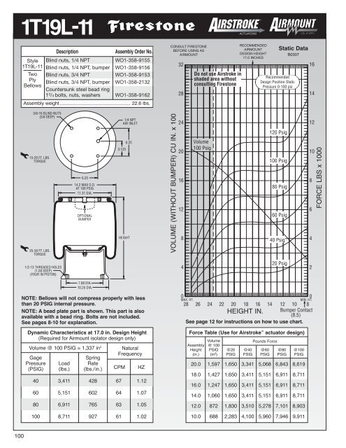
HOW TO USETHE STATIC DATA CHARTWe also refer to this chart as the load/deflection(L/D) curve for an air spring. The force [1] is givenon the right hand axis vs. the air spring height [2]as shown along the bottom axis; thus, load vs.deflection. The internal volume [3] is also givenalong the left hand axis, again vs. height [2]. It iscalled static data because the air spring is in astatic, or non-moving, constant pressure condition.In almost all cases the static curves were runusing a two ply bellows; however, where a fourply bellows is available, use the two ply chart for italso.AIRSTROKE ACTUATIONThe important considerations are minimumheight [4] (3.0 inches) and maximum recommendedheight [5] (10.1 inches). Subtracting onefrom the other gives the stroke potential for thispart (10.1 – 3.0 = 7.1 inches). As an actuator, theentire stroke may be used, or any potion thereof.Ignore recommended airmount design height [6]and the corresponding darkened line [7]. Thisheight is important in using the air spring as anisolator (AIRMOUNT). It has nothing to do withthe concern here of actuation. To determine theforce at any given height, simply move up theheight line to where it intersects any of the staticpressure curves. Then move to the right andread from the force scale [1].EXAMPLE: At 80 psig, what is the force using a#22 from 4.0 to 9.0 inches, or 9.0 – 4.0 = 5.0 inchstroke? See [8] for force at 4.0 inches (7,180 #)and [9] for force at 9.0 inches (4,670 #). Thisexample illustrates the primary differencebetween Firestone Airstrokes and conventionalair cylinders. Air cylinders have a constant areafor the pressure to work against, or constanteffective area. the effective area and force of anair spring changes as the height changes.(Thereis one exception: notice the plateau section ofreversible sleeve 1T type curves.)VOLUME (WITHOUT BUMPER) CU IN. x 100[3]1110987527654349321[6]RecommendedAirmountDesign Height9.5 InchesDo not use Airstroke inshaded area withoutconsulting Firestone[13][10][7][15][14]Volume100 Psig[12][9]Static Data122712010080604020 Psig[8][11]11109877,180654,6704,2804MAX. HT. [5]MIN. HT.[16][4]12 11 10 9 8 7 6 5 4 3[2] Bumper ContactHEIGHT IN.(4.2 IN.)321FORCE LBS x 1000[1]12
In the example the effective area of a #22, at 4.0 inches usingthe 80 psi curve, is:7,180 lbs.80 Ibs/in 2 = 89.8 in 2at 9.0 inches in height it is:4,670 lbs.80 Ibs/in 2 = 58.4 in 2An air cylinder with 89.8 in 2 of area would have an 80 psi curveas shown by dotted line [10].The volume curve [3] may also be of importance:a. If one needs to know the amount of free air (then compressedby the compressor) to perform a desired operation.b. If the actuation must be completed quickly and calculationsof flow through the air inlet (orifice) are required.In each case above, the change in internal volume is required.Read up from the two heights involved to the intersecting pointwith the volume curve. Then move to the left and read from thevolume scale. In the example at 4.0 a #22 (notice most volumecurves are at 100 psig) has an internal volume of 349 in 3 [11]and at 9.0 the volume is 752 in 3 [12]. The change in volume isthen 752 in 3 – 349 in 3 , or 403 in 3 . The volume at minimumheight (349 in 3 ) would not be subtracted if exhausting the airspring to atmospheric pressure.Notice the shaded area [13]. We do not recommend that anair spring be used at heights extending into this section. The“beginning of the shaded area” for a #22 is at 101 inches [5].SEE PAGE 15 FOR A MORE DETAILED DISCUSSION OFACTUATION.AIRMOUNT ISOLATIONBecause of lateral stability considerations (see page 23 formore details) we recommend that each air spring be used at aspecific height when used as an isolator. This specific height iscalled the “Airmount design height” [6]. The vertical line runningthrough this height [7] is darkened so that it is easy to seewhere it intersects the static curves for load readings.EXAMPLE: Support a 4,100 pound load with an air spring.Would a #22 be appropriate, and if so, at what height? Theheight isn’t much of a problem, as this part SHOULD BEUSED AT 9.5 INCHES. Simply move up the darkened line towhere it intersects 4,100 Ibs [14]. That point falls between the80 and 60 psig curves. Exactly what pressure would berequired? Use the formula:Effective Area =Load (Ibs.)Pressure (Ibs/in 2 )Determine the effective area at 9.5 inches (using the 80 psigcurve, since 80 psig would be closer to our exact pressurethan 60 psig), or:Effective Area = 4,280 Ibs. [15] = 53.5 in 280 Ibs/in 2Then divide the actual load by the effective area:4,100 Ibs. = 76.6 PSIG53.5 in 2The pressure required to support 4,100 Ibs. with a #22 at adesign height of 9.5 inches is therefore 76.6 PSIG.Please note that the static data can be converted to dynamicdata (the air spring is in motion) by applying the formulas thatare presented in the Airmount isolation section on page 22.SEE PAGE 21 FOR A MORE DETAILED DISCUSSION OFVIBRATION ISOLATION.INTERNAL RUBBER BUMPERSSome parts are available with internal rubber bumpers. Wherea bumper is available, it is shown as a dotted line in the crosssectional view of the air spring. Additionally, please note that:1. the minimum height is increased to the “bumper contact”point [16] (this reduces the total available stroke somewhat,by 4.2 – 3.0 = 12 inches in our #22 example), and2. the order block contains the proper ordering numbers forparts with bumpers.13
BASIC PARAMETERS APPLICABLE TOBOTH AIRSTROKE ACTUATORS ANDAIRMOUNT ISOLATORSMEDIAAir springs are designed for use with compressed air. Nitrogenis also acceptable. Air springs may be filled with water or waterglycol(automotive antifreeze) solutions. If water is to be used,rust inhibitors should be added to protect the end closures. Tworeasons for liquid filling an air spring are:1. To reduce the internal volume of air (and therefore, increasethe natural frequency of the air spring) and,2. To use a media which is incompressible. Accurate positioningwould be one reason to do this.Petroleum base fluids (most hydraulic oils fall into this category)are NOT RECOMMENDED. Moderately lubricated air will notharm the bellows.PRESSURE1. 100 PSIG MAXIMUM FOR 2 PLY.2. 175 PSIG MAXIMUM FOR HIGH STRENGTH.We recommend that there be a minimum three times safety factorbetween maximum internal air pressure and burst pressure.So, as an example, if 100 psig is required, the burst should be at300 psig or greater. For convoluted air springs, the burst pressuredecreases as height increases. Therefore, the determiningfactors are twofold: What is the maximum height into extensionand what is the internal pressure at that point? Please see theAirstroke Inflation Pressure Chart (for single, double, and tripleconvoluted air springs) on page 17 for specific pressure vs.height information.For AIRMOUNT applications (where the part is used at aheight very close to the shaded area), it is best to stay within100 psig maximum for a two ply, and 150 psig maximum for afour ply or high strength cord air spring.STORAGEThe best storage environment is a dark, dry area at normalroom temperature.TEMPERATURE1. STANDARD BELLOWS. Our standard industrial air springsshould be limited to use in the range:– 35° F to + 135° F.2. ALL NATURAL RUBBER (LOW TEMPERATURE COM-POUND). A few of our industrial air springs are available inall natural rubber construction. This increases the acceptablecold or low end of the scale to – 65° F. The range thenbecomes – 65° F to +135° F.3. EPICHLOROHYDRIN (HIGH TEMPERATURE COM-POUND). Most convoluted parts are available in thismaterial. The operating temperature range for it is: 0° F to225° F. Additionally, Epichlorohydrin has very good oil resistance.ALL EPICHLOROHYDRIN APPLICATIONS MUSTBE APPROVED BY FIRESTONE. For more information onEpichlorohydrin (also known as Herclor), ask forTechnigram number 111.4. NEOPRENE (HIGH TEMPERATURE COMPOUND).Neoprene is more resistant to damage from oil. For thisreason, Firestone Neoprene has been used as the insidelayer in two configurations to reduce the hazard of having oilin the pneumatic plumbing system. The third configurationincludes an outer layer of Firestone Neoprene for applicationsthat expose the exterior of the air spring to an oilenvironment. In addition, Firestone Neoprene is able towithstand higher temperatures than natural rubber (-35º to+165º F).CONTAMINATESShielding should be used to protect the bellows from exposureto hot metal, sand, petroleum base fluids, acids, etc. Pleaseconsult Firestone if you wish to know how the bellows will withstanda specific contaminant (For liquids such as acids, it isimportant to know both concentration and temperature).WARNINGDO NOT INFLATE ASSEMBLY WHEN IT IS UNRESTRICTED. ASSEMBLYMUST BE RESTRICTED BY SUSPENSION OR OTHER ADEQUATE STRUC-TURE. DO NOT INFLATE BEYOND PRESSURES RECOMMENDED INDESIGN LITERATURE (CONTACT FIRESTONE FOR INFORMATION).IMPROPER USE OR OVERINFLATION MAY CAUSE ASSEMBLY TOBURST CAUSING PROPERTY DAMAGE OR SEVERE PERSONAL INJURY.14
AIRSTROKE ACTUATIONSELECTION1. Refer to the selection guide on page 32 for Airstroke forceand stroke capabilities. After your list of possibilities has beenreduced to one or two air springs, then turn to the individualdata page for more detailed information on those parts.2. STROKE: The maximum STROKE CAPABILITY is the differencebetween the height corresponding to the “start ofthe shaded area” minus the minimum height. This entirestroke, or any portion thereof, may be used. If an internalrubber bumper is required, please note that the minimumheight is increased, and therefore, the total stroke isdecreased.3. FORCE: Read the forces directly from the static data chart,or, use the force table located under the chart. Notice thatthe force generally decreases as height increases. This featureis discussed in detail on page 12 in the section entitled“How to Use the Static Data Chart.”4. SELECT THE END CLOSURES AND AIR INLET SIZE:Most Airstroke actuators are available with permanentlyattached plates or bead ring attachments. If an alternate endclosure option is available, it is so stated under the crosssectional view of the part. Please refer to page 6 for adetailed discussion of end closure options.DOWN AND UP STOPSPositive stops in both directions (compression and extension)should always be used with Airstroke actuators .1. In COMPRESSION, the minimum height shown for each airspring is at, or slightly above the PINCH POINT of the bellows.Here is a #22 shown in the collapsed or “pinch point” condition:2. In EXTENSION, an upstop is required to prevent the airspring from overextending at heights into the shaded area ofthe graph. The reasons for this are twofold: a) the life of thebellows may be reduced and b) the crimp may open up,allowing the bellows bead to blow out of the metal end closure.There are many ways to design-in an upstop, includinga. a chain,b. a cable,c. contacting a metal stop, etc.RETURNAn Airstroke actuator is a single acting device. To return theAirstroke to its minimum height (for another cycle or stroke),some return force must be used. Gravity acting on the loadmay be all that’s required. The force to collapse the convolutedtype Airstrokes to minimum height is given in the order blocksection for each part. If the load is not sufficient, then a secondAirstroke or coil spring may be required.GUIDINGAn Airstroke follows the path of least resistance; therefore, theactuator should be guided in most instances. This is often easilyaccomplished in the mounting geometry.ANGULAR CAPABILITYAn Airstroke actuator can stroke through an arc (without a clevis).Angular motion of up to 30 degrees is possible. Whenusing an actuator with the mounting plates at an angle to eachother, observe the following:a. Measure force at the height between the plate centers.b. Measure maximum height at the side separatedthe furthest.c. Measure minimum height at the side collapsed the most.3.0The bellows can be damaged if allowed to constantly bottomout as shown above; therefore, a downstop is requiredto prevent this. An external downstop can be something assimple as a steel block and should be sized at or slightlygreater than the minimum height of the Airstroke. In our #22example, the block would need to be at least 3.0 incheshigh. If an external downstop cannot be used, many partsare available with internal rubber bumpers (shown as adotted line in the cross-sectional view of the air springwhere available).15
Angular Capability continuedThese measurements must fall within the guide lines for thatparticular part. Consider style #22 in the following scissorsarrangement:Please note that the air spring forces are not additive in thisconfiguration. A method for guiding, which also illustrates onecenter ring concept for mounting the two parts together at themiddle, is illustrated below:CalculateForce HereMax Ht(Must be ≥ 3.0)Max Ht#22(Must be ≤ 10.1)Center RingPivotPointReversible sleeve Type 1T parts may also stroke through anarc. In this case, care must be taken to prevent the bellows fromrubbing (internally) against itself where it rolls over the piston:Customer MustSupply ButtonHead-Socket HeadCap ScrewsBellows mustnot rub againstitself here.HORIZONTAL MISALIGNMENTThe upper and lower bead plate centers (or mounting platecenters in the case of a bead ring type attachment) may be outof line somewhat without injury to the bellows. Our “rule ofthumb” for convoluted type Airstrokes is one inch misalignmentallowed per convolution. So, a single convoluted air springmay be out of line by as much as 1 inch, a double by 2 inches,and a triple convoluted air spring by 3 inches.DESIGN ENVELOPEAdequate clearance should be provided around the Airstroketo prevent puncturing or rubbing of the bellows. The maximumdiameter @ 100 psig for each Airstroke (bellows) is locatedjust above the cross-sectional view of the air spring.STACKINGIt is permissible to stack Airstrokes (one on top of another) toincrease stroke; however, the center plate (or plates) connectingthe two or more Airstrokes MUST BE GUIDED.FAIL SAFE DEVICESSome applications require the use of fail safe mechanisms(such as a mechanical lock-out on a scissors lift) to preventdamage or injury in the event of an air system failure.VACUUMAn Airstroke can withstand a small amount of vacuum withoutinjury to the bellows. The maximum amount of acceptable vacuumis dependent upon the bellows’ size, the height in use, andwhether it is a two ply or high strength (fabric) air spring. (A highstrength Airstroke bellows has a “stiffer” wall than a two ply;therefore, it is less susceptible to dimpling and deformationinward). It is generally best to use only single convoluted airsprings under vacuum.An Airstroke Design Parameter Worksheetcan be found on page 105.16
AIRSTROKEACTUATOR PROBLEM SOLVERSGATE VALVE OPERATORGLUING PRESSWEB TENSIONING DEVICEDIE STRIPPERAIRSTROKEACTUATORPAPERKNIFE SPRING ACTUATORQUENCH TANK ACTUATORROTATIONLOGKNIFEQUENCH TANKAIRSTROKE ACTUATORSUPPER & LOWER POSITIVE STOPSPAPER SIZING PRESSPICKLING TANK ACTUATORPRESSAIR LINESPIVOTACID TANKACIDFRAMEWIRE COILSQUICK LOCK DEVICEPRESSURE ROLL FOR CALENDER18
AIRSTROKEACTUATOR PROBLEM SOLVERSMISSILE ASSEMBLY FIXTURECORE STRAIGHTENERAIRSTROKEACTUATORBELT TAKE UPROLLER FRICTION BRAKEFRICTION PADAIRSTROKEACTUATORPIPE INDEXING THREADINGEND VIEW OF PIPEOSCILLATING DOCTOR FOR PAPERCALENDER ROLLDOCTORCYLINDERFORMING PRESSCABLE TENSIONING DEVICEPRESSPLATENBAG FLATTENERTORSIONAL FRICTION BRAKEBAG OFMATERIALTO BEFLATTENEDPOWEREDROLLERDRIVEBELTLINESHAFTAIRSTROKEACTUATORROLLERSUPPORTFRAMETORQUE TUBEAIRSTROKEACTUATORSBRAKE BUSHING19
AIRSTROKEACTUATOR PROBLEM SOLVERSAIRSTROKEACTUATORHINGED GATEAIRFITTINGHOT FOIL STAMPING PRESSAIRSTROKEACTUATORCOMPRESSED POSITIONEXTENDED POSITIONWEIGHHOPPERTORSIONSPRINGHINGECLOSEDOPENACTUATED HEAVY DUTY SEALERPIVOTED CLAMPING DEVICEAIRSTROKEACTUATORAIRSTROKE ACTUATED ROLLER STOPHINGED ACTUATED GRAVITY GATERUBBERSTOPAIRSTROKEACTUATORADJUSTABLECOLLAPSEHEIGHTRETURN TENSIONSPRINGAIRSTROKEACTUATORVERTICAL ACTUATED DRIVE TABLESCISSOR LIFTTOP OF CHAIN IN HIGH POSITIONTOP OF CHAIN IN LOW POSITIONAIRSTROKEACTUATORFIXED STOPCASE PACKERCONVEYOR TRANSFER ACTUATOR20
AIRMOUNTSELECTION AND ISOLATION FORMULARefer to the selection guide on page 33 for Airmount load andisolation capabilities. Follow this procedure:1. LOAD CAPACITYSelect one or two Airmounts that can support the load at eachmounting point. It is normally best to design for pressures inthe 60 to 80 psig range. Consider only the 1M1A-0 and thesingle and double convoluted types at first. Please notice thatin the range of 210 to 63,890 pounds you will, in most cases,find both a single and double convoluted style part which willsupport the load.2. DETERMINE ISOLATION EFFECTIVENESSSelect the disturbing frequency that is closest to the actualforced frequency (400, 800, or 1500 cpm). Then check the percentageof isolation for the parts that were selected in 1 above.3. DETERMINE DESIGN HEIGHTTHE AIR SPRING SHOULD BE USED AT THE DESIGNHEIGHT GIVEN. The double convoluted part is used at adesign height somewhat higher than its single convolutionequivalent. Make sure that the design height falls within theheight restrictions. Also, the double convoluted part will show ahigher percentage of isolation (less transmitted vibration) thanthe single convoluted air spring. The reason for this is that thedouble convoluted part has a greater internal volume of airthan the single convoluted version of the same size. At disturbingfrequencies in the 400 to 800 cpm range, the doubleconvoluted part is a significantly better vibration isolator thanthe single convoluted part. At disturbing frequencies of 800 to1500 cpm, the gap closes considerably. At frequencies of1500 cpm and above, the difference is negligible.4. DETERMINE EXACT INTERNAL PRESSUREAND ISOLATION EFFECTIVENESSThe chances are that your specific vibration problem does notfall neatly into the load and disturbing frequency criteria as presentedin the selection guide.Therefore, once a preliminary part selection has been made,turn to the individual data page for that part in order to determinethe specific internal pressure required and thepercentage of isolation attainable.VIBRATION ISOLATIONCONSIDER THIS EXAMPLE:Isolate a vibrating screen which weighs a total of 16,400pounds, preferably with one isolator at each corner. The vibratingmechanism is rotating at a speed of 850 rpm (cpm) with atotal stroke of 5 /16 inch.a. Determine the load at each mounting point:16,400 = 4,100 lbs.4Scan down the 80 psig load column in the selection guide. Itappears that either a #19 or a #22 will support the load at apressure between 60 and 80 psig.b. Determine Isolation Effectiveness.Read the % of Isolation at 800 cpm for the #19 and #22(since 800 is closest to our machine speed of 850 cpm). A #19is at 96.0% and a #22 is at 98.2%. Looking at isolation effectivenessin terms of % TRANSMISSION, the #19 will transmit100 – 96.0, or 4.0% of the vibrations. A #22 will transmit100 – 98.2, or 1.8% of the vibrations. So, even though theredoes not seem to be much difference between 96.0% and98.2% isolation, the #22 is in fact a better isolator by approximatelya factor of two when comparing transmitted vibration.c. Determine Design Height.Let’s say we have chosen the #22 because 96.0% isolation fora #19 is considered to be too low. A #22 should be used at 9.5inches as shown in the second column on page 33.d. Determine Exact Internal Pressure and Isolation Percentage.Turn to page 61 for detailed information on the #22.a) What exact pressure will be required to support the loadof 4,100 Ibs? Refer to the information in the block entitled“Dynamic Characteristics at 9.5 in Design Height.”4,280 lbs. = 53.5 in80 lbs/in 2 = effective area @ 9.5 inches2@ 80 psigDivide the actual load by the effective area:4,100 lbs. = 76.6 psig required to support53.5 in 2 4,100 lbs. at 9.5 inches21
AIRMOUNTb) What exact isolation will be attained?Use the formula:% Transmission = ( )1002f f – 1f nWhere: f f = Forced Frequencyf n = Natural FrequencyThe forced frequency is 850 cpm Read the natural frequencyfrom the line at the load and pressure closest to the actual situation,or 106 CPM (@ 80 psig and 4,280 Ibs.):% Transmission = 1002– 1850( 106)% Transmission = 1.6%% Isolation = 100 – % Transmission% Isolation = 100 – 1.6% Isolation = 98.4%Notice that the natural frequency of an Airmount changes onlyslightly with variations in pressure and load. Therefore, whenworking at pressures other than 40, 60, 80, or 100 psig, % isolationcan be calculated quite accurately using the “closest”natural frequency and the formula above.DYNAMIC SPRING RATE FORMULASpring rate is a different matter. Unlike most conventionalsprings, the rate of an Airmount is not constant. It is a functionof the change in effective area, volume, and pressure fromdesign height. To determine the rate of an Airmount, use thefollowing formula:[ ( ) ( ) ]1.38 1.38V 1 VK=[[P g +14.7] 1.38 11.38A c V – Ae –14.7(Ac c V e–A e )] lbs1inchWHERE:K = Vertical Spring Rate in Ibs./inchP g = Gauge Pressure at design heightlbs( in ) 2A c = Effective Area at 1 /2 inch below design height (in 2 )A e = Effective Area at 1 /2 inch above design height (in 2 )V 1 = Internal Volume at design height (in 3 )V c = Internal Volume at 1 /2 inch below design height (in 3 )V e = Internal Volume at 1 /2 inch above design height (in 3 )VIBRATION ISOLATIONConsider the same #22 example: What is the vertical springrate with a load of 4,100 pounds at a design height of 9.5inches? Refer to the static data chart on page 62. Again,our “closest" pressure is 80 psig, so we'll need to read theappropriate data from the 80 psig curve.The 80 psig information at 1 /2 inch above design heightwould fall at the 10.0 inch height line, and 1 /2 inch belowdesign height would fall at the 9.0 inch height line. (In thisexample, we can read loads from the force table). Theinformation at design height is located in the “DynamicCharacteristics Block.” So,K = UnknownP g = 76.6 psig (see page 13)A c = 58.4 in 2 = 4,670 lbs.( 80 lbs/in)2A = 47.6 in 2 = 3,810 lbs.80 lbs/in 2e ( )V 1 = 782 in 3V c = 752 in 3V e = 809 in 31.38 1.38K=[ [P Vg +14.7] A 1 Vc 1.38 1 – Ae1.38 –14.7(Ac –AV e c V e)] lbs1inchK=[ [76.6+14.7] 58.4 1.38 1.38782782[ ( ) –47.6 ( ) ] –14.7752 809 (58.4–47.6)1inchK = 1,324 lbs/inchNATURAL FREQUENCY FORMULAOnce the spring rate is determined, calculate the Airmountnatural frequency (for an undamped system) as follows:f n= 188 √ K LWhere:f n = Natural Frequency in cycles per minute (cpm)K = Rate (Ibs/inch)L = Load (pounds)in our example:f n= 188 √1,3244,100f n = 106.8 cpm[ ( ) ( ) ]22
AIRMOUNTVIBRATION ISOLATIONUp to this point, only the weight and disturbing frequency havebeen discussed. THERE ARE MANY OTHER IMPORTANTCONSIDERATIONS:CENTER OF GRAVITYAn Airmount isolation system is inherently soft (easily deflected);therefore, precautions must be taken to insure that thesystem is stable. First, consider the location of the center ofgravity (c.g.). Ideally, the Airmounts should be located on thesame plane (parallel to the ground) as the center of gravity.Where this is not possible, follow this guideline: The distancebetween the most narrow mounting points should be at leasttwice the height of the center of gravity.Height 48"Width 46"Length 50"LATERAL RATES AND STABILITYSingle and double convoluted air springs SHOULD BE USEDAT THE DESlGN HEIGHTS GIVEN, because that is the pointof maximum lateral rate or stability. The lateral rate decreasesas the Airmount height decreases. Consider a #22 again at80 psig:Height Lateral Rate Vertical Rate9.5 inch (design height) 325 lbs/in 1,373 lb/in8.5 inch 212 lbs —In the above example, the most narrow distance between twoAirmounts is 46 inches The height to the c.g. is 48 inches;therefore, this system does not meet our guideline. Two possiblesolutions would be:1. Increase the base dimensions to meet our guideline byincreasing both the width and length to at least 48 x 2 or96 inches.2. Locate the Airmounts at the c.g. as shown above (in thenext column).7.5 inch Unstable —Notice that the #22 becomes unstable in the horizontal or lateraldirection when moving down only two inches from design height.23
AIRMOUNTAt design height and without an auxiliary reservoir, the singleand double convoluted parts follow this pattern; i.e., the lateralrate varies from 1 /5 to 1 /2 of the vertical rate (only the largerhigh strength parts get as high as 1 /2). Notice the #22 isapproximately 1 325/4( 1,373).Going back to the original example ofa vibrating screen which weighs 16,400 Ibs. mounted on four#22’s (@ 9.5 inches), a side load of 1,300 pounds (325 x 4)would deflect the entire suspended mass by one inch.TRIPLE CONVOLUTED ANDREVERSIBLE SLEEVE TYPE PARTSBoth of these types are unstable laterally (except for the1M1A). Due to low natural frequencies, both can be excellentisolators; however, do not use these two types as Airmountisolators without consulting Firestone (for special guidelinesand precautions).DESIGN ENVELOPEAdequate clearance should be provided around the Airmount toprevent puncturing or rubbing of the bellows. The maximumdiameter @ 100 psig for each Airmount (bellows) is shown justabove the cross sectional view of the air spring.SAFETY STOPSIt is normally recommended that positive stops be installed in alldirections; i.e., into compression, extension, and laterally.Positioning of the vertical stops depends upon the amplitude ofmovement, both during normal operation and startup and shutdown.A good “rule of thumb” is ± 1 /2 inch from design height forvertical stops and also ± 1 /2 inch (horizontally) for lateral stops.INITIAL INSTALLATIONNEVER use Airmounts to lift equipment into place, due to the lateralinstability at lower air spring heights as discussedpreviously. Equipment should be rested on stops set slightlybelow design height and raised into position for isolation.STARTUP AND SHUTDOWN/RESONANCE AND AMPLIFICATIONResonance is the condition where the forced frequency of thevibrating system is at the natural frequency of the suspension.When this happens, AMPLIFICATION of movement occurs.Going back to our vibrating screen example again, if the normalstroke is 5 /16 of an inch, during startup and shutdown (asthe machine goes through resonance), the amplitude ofmovement will be multiplied somewhat. So, while the machineis building up to speed and slowing down, the stroke may beamplified in the range of 1 /2 to 1 1 /2 inches. The longer themachine takes to go through resonance (to build up to, orslow down from full operating speed), the larger the amplitudeof movement.VIBRATION ISOLATIONISOLATING AN UNBALANCED MASSThe primary concern in this case is the amplitude of movement.It is dependent on:1) The ratio of the unbalanced moving mass to the totalsuspended mass, and2) The ratio of the speed of the unbalanced moving mass(forced frequency) to the natural frequency of the Airmounts.The addition of damping to the isolation system (shockabsorbers) will reduce the large amplitude of movementexperienced during resonance.If the amplitude of movement is too great, one possible solutionwould be to add an inertia base in order to increase theratio of the total suspended mass to the moving unbalancedmass. A good “rule of thumb” is 10:1, respectively.LOW PRESSURE OPERATIONThe lateral rate of a single and double convoluted styleAirmount decreases with decreasing internal air pressure(becomes unstable). Consult Firestone if you plan on operatingan Airmount at less than 40 psig.EFFECT OF AN AUXILIARY RESERVOIRThere is a direct relationship between natural frequencyand isolation effectiveness. Generally, the lower the naturalfrequency, the better the isolator (or higher percentage ofisolation). As previously mentioned, a double convolutedAirmount has a lower natural frequency than a single convolutedtype (of the same size) because it has moreinternal air volume. We can use this principle to lower thenatural frequency of an air spring by adding an auxiliaryreservoir (pressure vessel) externally to the Airmount. Thiseffectively increases the air spring volume and reduces itsnatural frequency.In order for the reservoir to work properly, there must be afree flow of air between the Airmount and reservoir.Therefore, it should be mounted as close as possible to theAirmount. Additionally, a bead ring attachment is the bestend closure choice as the hole in the upper mounting platecan be sized as large as the inside diameter of the bellows(at the top). A 3 /4" NPT air inlet will restrict the flow of airsomewhat, but can be used as long as it is understood thatthere is some throttling effect.Going back to the #22 example, an auxiliary reservoir ofthree times the internal volume of the air spring at designheight (approximately 10 gallons) will reduce the naturalfrequency from 106.8 cpm to 90.2 cpm. The spring ratealso decreases, from 1,324 Ibs./inch to 944 Ibs./inch.24
AIRMOUNTDAMPINGCDamping is defined as the ratio: C cWHERE: C = System DampingC c = Critical DampingThe damping ratio inherent in an Airmount is in the order of.03. This damping number is so small that the formulas presentedin this section assume it to be zero.PLUMBING SYSTEMSThere are three basic ways of controlling an air suspendedisolation system:1. Tank Valve System With a tank valve in each Airmount,each air spring is then inflated individually. The pressurein each must be checked periodically, because air willpermeate through the bellows.For an idea of the permeation rate, a #116 will lose approximately30 psig over a period of one year (from 100 psig to70 psig). Please see page 7 for a picture of a 1 /4" NPT tankvalve.2. Three Point Regulated System The Airmounts can beconnected directly to the factory compressed air systemusing pressure regulating valves. This eliminates theVIBRATION ISOLATIONneed for periodic inspections. The air springs should alwaysbe connected in clusters so the mass is supported with onlyTHREE REGULATORS. This is illustrated below (in theprevious column) for both a four and eight Airmount system:3. Three Point Leveled System Height control can be providedby adding height control valves to the system.Again, there should be only THREE POINTS OF CON-TROL, or in this case, three leveling valves. Attemptingto use more than three control points often results in thevalves hunting or fighting one another. There are sensingsystems available to control heights within ±.001 inch.Truck type leveling valves can provide accuracy to ± 1 /16inch. A three point, eight air spring, leveled system isillustrated below:LEVELINGVALVEAIRSPRINGAIRSPRINGAIRSPRINGAIRSPRINGREGULA-TORSTO AIRSUPPLYAIRSPRINGAIRSPRINGREGULATORSAIRSPRINGAIRSPRINGCHECKVALVETO AIRSUPPLYAIRSPRINGAIRSPRINGLEVELINGVALVELEVELINGVALVEAIRSPRINGAIRSPRINGCHECKVALVESAIRSPRINGSAIRSPRINGSREGULATORSTO AIRSUPPLYDescriptionTime Delay ValveOrder No.WC1-<strong>358</strong>-3592AIRSPRINGSAIRSPRINGSCHECKVALVESAn Airmount Design Parameter Worksheetcan be found on page 107.25
AIRMOUNTVIBRATION ISOLATIONISOLATION CHARTFORCED FREQUENCY (ff)HERTZ5041.733.22516.71513.311.7108.36.75.04.2CPM30002500200015001000900800700600500400300250PercentIsolation99.999.5 99 98 97 9695 90 80 70 60ResonanceAmplification3.32002.51.7150100300.50 0.67 400.83 501.0 601.33 801.671001502.50 3.332003005.00 6.67 4008.33 50010.0 60013.3 800 100016.7NATURAL FREQUENCY (f n )CPMHERTZ26
AIRMOUNTISOLATION PROBLEM SOLVERSVIBRATING PACKERBIN HOPPERCOMPRESSORCOMMERCIAL LAUNDRY MACHINE27
AIRMOUNTISOLATION PROBLEM SOLVERSCONTROL BOOTHVIBRATING SCREENBLOWER AND MOTORCONTROL PANEL28
MISCELLANEOUS APPLICATIONSThe air spring provides a unique solution for many actuationand isolation applications the world over. Besides the commonapplications, there are many that are not readily recognizedbecause of the air spring’s unique construction. Listed beloware some miscellaneous applications.SHOCK IMPACT ISOLATIONThe air spring is frequently used in shock impact isolationapplications. This air spring application is commonly found insaw mills as the means to both absorb the shock of a fallinglog, and then by actuating the air spring, to lift and transfer alog onto a conveyor. Because of the properties of both air andrubber, the air spring is an ideal solution to this problem.Without it, the mechanism and surrounding structure wouldsuffer fatigue and fail prematurely due to the intensity of theshock from the falling log. Refer to the problem solver sectionon the following pages for miscellaneous applications.VACUUM PUMPIt is possible to drive an air spring mechanically in order to createa vacuum. The air spring can withstand a small amount ofacceptable vacuum without injury to the bellows. The maximumamount of tolerable vacuum is dependent upon thebellows’ size, height and whether it is a 2 ply or high strengthair spring. It is generally best to use only the single convolutedair spring for this purpose. Refer to the problem solver sectionon the following pages for miscellaneous applications.AIRSPRINGROTATINGCAMEXTENDEDCOLLAPSEDRETURNSPRINGHEATINGPLATENVACUUM CYLINDERSPRING RETURNPREPRINTED LABELSINDEXED INPACKAGEOF MEATAIRMOUNTINDEXING CONVEYORSYSTEMCHECKVALVECONVEYOR RAILCARRIAGEINFLATABLE CHUCKBy restricting the height internally of a bead ring style air spring,the rubber walls will extend in an outward fashion. In thisarrangement the air spring can be used as an inflatable chuck.The air will need to be introduced via the same mechanism thatrestrains the air spring’s height. Refer to the problem solversection on the following pages for miscellaneous applications.PROTECTIVE BOOT ANDFLEXIBLE CONNECTORAn air spring bellows, with a bead ring type attachment, can beused as a protective boot or flexible connector. Due to the flexibleconstruction of the air spring and the ability to handle bothmisalignment and angular movement, the air spring is a suitablesolution to this problem. To protect the inner surface fromthe flow of material, an inner sleeve may be required. Refer tothe problem solver section on the following pages for miscellaneousapplications.ROTATINGSHAFTAIR ENTRANCETUBEAIRSTROKEPIPEAIRSTROKEHYPALONSLEEVECAM FOLLOWERThe introduction of an air spring as the cam follower canextend the life of the cam greatly. Surface wear is reduced byremoving the rigidity and friction of typical cam followers. Withthis reduction of wear comes continually smooth operationsand overall minimization of fatigue. Refer to the problem solversection on the following pages for miscellaneous applications.For more information, call your local stocking distributor or theFirestone applications engineer at the phone number on theback cover of this design guide.29
MISCELLANEOUS PROBLEM SOLVERSROBOTIC COUPLINGCONVEYOR END STOPAIRSTROKEEND VIEWMOUNTAIN/TRAIL BIKESHOCK ABSORBER TEST SYSTEMSCREENING MACHINE COVER CLAMPPIPE CRAWLERDELICATE ELECTRONIC EQUIPMENTVIBRATING SCREEN30
MISCELLANEOUS PROBLEM SOLVERSSHEET WELDING CLAMPSWASH PLATE MOTORPERFECT BOUND MAGAZINE CUTTERWAVE POWER MODULECHECK VALVE LAPPINGSELF ALIGNING DEVICEAIR BLAST GENERATORSOLAR TRACKER31