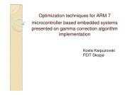
An RFID application in embedded systems
An RFID application in embedded systems
An RFID application in embedded systems

Create successful ePaper yourself
Turn your PDF publications into a flip-book with our unique Google optimized e-Paper software.
Introduction RadioFrequency IDentification Contactless – radio subject identification Fast, efficient and reliable method of identification Commonly used <strong>in</strong>:- automotive <strong>in</strong>dustry (key transponders)- access control <strong>systems</strong>- public transport ticket<strong>in</strong>g- asset management- ePassports etc.
Hardware architecture of the <strong>RFID</strong> electronic lockElectrical schematic
Hardware architecture of the <strong>RFID</strong> electronic lock<strong>RFID</strong> module <strong>RFID</strong> operates on the follow<strong>in</strong>g standard frequency carriers:▪ Low-Frequency (LF) [125 KHz – 139 KHz] ISO14443A/B▪ High-Frequency (HF) [13.56 MHz] ISO14443A/B,ISO15693▪ Ultra-High-Frequency (UHF) [433 – 960 MHz]▪ Microwave [2.45 GHz +] The operat<strong>in</strong>g distance of the <strong>RFID</strong> module is directly proportional to thefrequency carrier; higher read<strong>in</strong>g range is achieved on higher frequencies Low-Frequency <strong>RFID</strong> modules are less sensitive to metal objects <strong>in</strong> thesurround<strong>in</strong>gs compared to higher frequency <strong>RFID</strong> modules Higher operat<strong>in</strong>g frequency though provides a larger data throughput andtherefore a faster identification of the subjects.
Hardware architecture of the <strong>RFID</strong> electronic lock<strong>RFID</strong> module Mediator between the microcontroller and the <strong>RFID</strong> usercards Provides the wireless communication l<strong>in</strong>k, (de)cod<strong>in</strong>g,(de)modulation of the data be<strong>in</strong>g exchanged between themicrocontroller and the contactless <strong>RFID</strong> cards Operat<strong>in</strong>g carrier frequency f C =13.56 MHz Operat<strong>in</strong>g distance od 7cm achieved Compliant to the ISO14443A standard Why was 13.56 MHz chosen as the carrier frequency?- <strong>RFID</strong> cards can be read at a maximum 10cm distance from the reader, which is ideal for an accesscontrol system.- The module’s antenna requires much less loops compared to LF readers’ antennas- Relatively fast data exhcange between the module and the card- <strong>RFID</strong> cards/transponders <strong>in</strong>tended for 13.56MHz operat<strong>in</strong>g frequency commonly have a largermemory capacity which allows a larger user flexibility
Hardware architecture of the <strong>RFID</strong> electronic lock<strong>RFID</strong> modulePr<strong>in</strong>ted Circuit Board Design Drawn <strong>in</strong> Proteus(ARES) v7.2 Manufactured <strong>in</strong> Hitech– Macedonia based onthe generated Gerberfiles Integrated PCB antennamade up of 4 turnsFront side viewBack side view
Hardware architecture of the <strong>RFID</strong> electronic lockCLRC632 <strong>RFID</strong> IC Basic element of the <strong>RFID</strong> module Made by NXP Semiconductors Supports ISO14443A/B, ISO15693, ICODE Completely <strong>in</strong>tegrated concept of (de)modulation,(de)cod<strong>in</strong>g, parity and error control and data verification Internal 512B EEPROM memory 64 <strong>in</strong>ternal 8-bit registers Digital, analog and radiofrequency section Allows <strong>in</strong>tegration of an antenna with a m<strong>in</strong>imum number ofexternal passive components SPI communication with the microcontroller LPC2148
Hardware architecture of the <strong>RFID</strong> electronic lockSPI <strong>in</strong>terface(Microcontroller LPC2148) SPI controller with <strong>in</strong>ternal configuration registers MASTER mode of operation 16-bit bidirectional shift data registerLPC2148SCK0MOSI0MISO0GPIO0.20SCKMOSIMISOSSEL
Hardware architecture of the <strong>RFID</strong> electronic lockSPI <strong>in</strong>terface(<strong>RFID</strong> module – CLRC632 <strong>RFID</strong> IC) Automatic <strong>in</strong>terface detection (SPI or parallel) A maximum data rate of 5 Mbps SLAVE mode of operation Has its own predef<strong>in</strong>ed protocols for writ<strong>in</strong>g and read<strong>in</strong>g the<strong>in</strong>ternal registers of the CLRC632CLRC632SCKMOSIMISOSSELA2A0D0ALE
Hardware architecture of the <strong>RFID</strong> electronic lockCLRC632’s SPI protocols(<strong>RFID</strong> module – CLRC632 <strong>RFID</strong> IC) The microcontroller <strong>in</strong>itializes the SPI comunnication bysend<strong>in</strong>g two bytes 0x00 to the CLRC632. Writ<strong>in</strong>g <strong>in</strong>to the CLRC632 registers Read<strong>in</strong>g the CLRC632 registers
Hardware architecture of the <strong>RFID</strong> electronic lock<strong>RFID</strong> cards Mifare 1k Classic (NXP Mifare технологија) Compliant to the ISO14443A standard A passive <strong>RFID</strong> transponder, f C = 13.56 MHz Maximum operat<strong>in</strong>g distance is specified at 10cm Internal 1kB EEPROM memory Unique 32-bit idenfitication number (Unique IDentifier) Supports NXP’s Crypto algorithm for safe transactions
Hardware architecture of the <strong>RFID</strong> electronic lockInternal structure of the card
Hardware architecture of the <strong>RFID</strong> electronic lockPhysical layer Cod<strong>in</strong>g and modulation (<strong>RFID</strong> module)- Modified Miller cod<strong>in</strong>g- 100% ASK modulation
Hardware architecture of the <strong>RFID</strong> electronic lockPhysical layer Cod<strong>in</strong>g and modulation (<strong>RFID</strong> card)- Manchester cod<strong>in</strong>g- Load modulation (us<strong>in</strong>g a sub-carrier at 847.5 kHz)
Hardware architecture of the <strong>RFID</strong> electronic lockPhysical layer Inductive coupl<strong>in</strong>g (K ~ 0.3) Wireless power transmission
Hardware architecture of the <strong>RFID</strong> electronic lockA block diagram of the card’slogical statesREQ- A request for open<strong>in</strong>g acommunication l<strong>in</strong>k with anexist<strong>in</strong>g <strong>RFID</strong> card <strong>in</strong> thereader’s fieldSEL + NVB- A command sent to thedetected <strong>RFID</strong> card <strong>in</strong> orderto read the full UID numberPOWER OFFIDLEREADYACTIVEPOWER OFFAfter 5 ms <strong>in</strong> the <strong>RFID</strong> reader’s field a card ispowered and ready to communicateCommand: REQ (0x26)Transition: IDLE - READYCommand: SEL (0x93) + NVB (0x20)Transition: READY - ACTIVEThe <strong>RFID</strong> reader shuts down the RF field afterread<strong>in</strong>g the UID number
Hardware architecture of the <strong>RFID</strong> electronic lockData layer of the RF l<strong>in</strong>k<strong>RFID</strong> moduleREQ (0x26h)REQ (0x26h)REQ (0x26h)SEL (0x93h)NVB (0x20h)RF wireless l<strong>in</strong>k<strong>RFID</strong> cardA card was detected!ATQ (0x04h)UID Byte 0UID Byte 1UID Byte 2UID Byte 3
Software architectureof the <strong>RFID</strong> electronic lock The program code is written <strong>in</strong> <strong>embedded</strong> C, the IAREmbedded Workbench 5.0 IDE was used Ma<strong>in</strong> features:- Periodical <strong>in</strong>terrogation of cards <strong>in</strong> order to save energy- Simple and easy to program new or delete exist<strong>in</strong>g cardsfrom the microcontroller flash database by present<strong>in</strong>g apredef<strong>in</strong>ed PROG or DEL card to the reader accord<strong>in</strong>gly- Timestamp and logg<strong>in</strong>g of the complete activity of the<strong>RFID</strong> lock <strong>in</strong> a .txt file placed <strong>in</strong> an SD card (1GB) <strong>in</strong> order toretrieve vital access control <strong>in</strong>formation later on- Flexible database management, can be stored <strong>in</strong> <strong>in</strong>ternalflash of the microcontroller or based on a removable SD card
Software architectureof the <strong>RFID</strong> electronic lock <strong>An</strong> overview of the procedures <strong>in</strong> the code:- void ScanCard()- <strong>in</strong>t CardType()- void Programm<strong>in</strong>gCard()- void Delet<strong>in</strong>gCard()- void VerifyCard()- void TimeStamp()- void Signalize(<strong>in</strong>t SignalType)
Software architecture of the <strong>RFID</strong> electronic lockBasic flowchart
Software architecture of the <strong>RFID</strong> electronic lock Procedure for programm<strong>in</strong>g new cards <strong>in</strong>to the database(PROG card)
Software architecture of the <strong>RFID</strong> electronic lockProcedure for delet<strong>in</strong>g exist<strong>in</strong>g cards from the database whenthe DEL card is detected <strong>in</strong> the reader’s field
Software architecture of the <strong>RFID</strong> electronic lock Procedure which determ<strong>in</strong>es the card type (USER, PROG orDEL)
Software architecture of the <strong>RFID</strong> electronic lock Procedure for check<strong>in</strong>g the privileges of the shown <strong>RFID</strong> cardand decision of accessvoid VerifyCard()Процедура за проверка даликартичката е овластена запристап до просторијатаDoes the card exist <strong>in</strong> thedatabase?yesSignalize(CARD_ACCEPTED)noSignalize(CARD_DENIED)EXITUnlock the door with a 3 seconddurationLock the doorEXIT
Software architecture of the <strong>RFID</strong> electronic lock Procedure for read<strong>in</strong>g the UID number from the <strong>RFID</strong> card
Possible upgrades Introduc<strong>in</strong>g an ethernet l<strong>in</strong>k to a local or remote server whichwould manage a whole system of <strong>in</strong>terconnected <strong>RFID</strong> locks Voice or visual notification of the access status (cardaccepted/denied/programmed/deleted etc) Stor<strong>in</strong>g lock-specific data <strong>in</strong>to the user’s <strong>RFID</strong> card <strong>in</strong>ternalEEPROM memory for greater flexibility and options Increase the operat<strong>in</strong>g distance (?) Visual C based software for manag<strong>in</strong>g the lock’s databasesand logs on a personal computer