Manual - Building Block Video CCTV
Manual - Building Block Video CCTV Manual - Building Block Video CCTV
NEUTRALSW1 UNUSEDSW8(on/off) Start Self Test - LEFT,RIGHT,WIPE,WASH/AUTOPAN,LIGHTS,IRIS OPEN,CLOSESW2 Iris OverrideON = 2.5 - 5.5V, OFF = 2.5 - 12VSW3/SW4 Aux selectionFunction SW3 SW4WASHER ON ONAUTOPAN OFF OFFSW8 ON = SELF TESTSW5,6,7 = UNUSEDBuilding Block Video LtdONSTATUS LEDSCABLEEven Flashing -Telemetry and syncok.Mainly ON - No TelemetryMainly OFF - No sync from cameraERRORON - Telemetry error.20mAtwisted pairtelemetry ifrequired.CABLEGROUNDIRIS OVERRIDEAUTO IRISIRIS OVERRIDE31 2 3 4 5 6 7 8ERROR1 2 3 4 5 6 7 1 2 3 4 5 6 7 8 9 1 0LEFTRIGHTWASH/AUTOPANWIPER17 Apex Park, Diplocks Industrial Estate, Hailsham, East Sussex, UK. BN27 3JU. Tel: +44 (0)1323 842727 Fax: +44 (0)1323 842728Tech Support: +44 (0)1323 444600 Web site for manuals/data sheets/application notes etc. www.bbvcctv.comEARTHLIVELIGHTSSELF-TEST AND DIAGNOSTIC SEQUENCESRY5 RY4 RY3 RY2 RY1NEURALEARTHAC OUTPUT1112NEUTRALEARTHCable compensation.Lift:Clockwise to increaseHF content.Gain:Clockwise to increaseoverall video level.Gain and Lift are factory preset for250M of RG59 cable.J5LIVEUNSWITCHEDOUTPUT.CAMERASUPPLY ETCF2 Output fuse ratingSupply Output Fuse230 230 5A T230 24 315mA T110 110 5A T110 24 630mA T24 24 5A TVideo InFrom CameraVideo OutTo Transmitter250M-RG59500M-CT125110Vac and 24Vacsupply options areavailable.This must bespecified at ordertime.230Vac standard.BBV 24VAC mk 2 option plugs intothis socket for 24Vac output.ALL J6 outputs are at supply levelor 24Vac when 24V option fitted.Rx200 Mark II ConnectionsThe diagnostic system and status check, which will activate each camera function for two seconds in turn, isactivated either locally by pressing a switch on the PCB or remotely from a BBV keypad. When testing thesystem locally, before initiating the diagnostic system and status check by turning SW8 ON momentarily,ensure that the Cable LED is on (i.e. either flashing or continuously). If not, this indicates that either thepower is not attached to the PCB, or there has been a major PCB error. Rectify accordingly.The Error LED flashes at a two-second rate during self-test. If the Cable LED fails to extinguish, then theunit is unable to self-tune and should be returned for repair.Order of function test:PAN LEFTPAN RIGHTWIPERWASHER/AUTOPANLIGHTSAuto Iris OpenAuto Iris CloseDiagnostic Check Complete, unitresets and continues normaloperation.Telemetry Receiver Installation HandbookRx200mk22 July 2004 Rev6Page_6
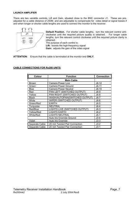
LAUNCH AMPLIFIERThere are two variable controls, Lift and Gain, situated close to the BNC connector J1. These are preadjustedfor a cable distance of 250M, and are adjustable to compensate for video detail or signal losses ifand when longer or shorter cable lengths are used to connect the monitor to the receiver.Default Position. For shorter cable lengths, turn the relevant control anticlockwiseuntil the required picture quality is obtained. For longer cablelengths, turn the relevant control clockwise until the required picture clarity isobtained.The purpose of each control is:Lift: boosts the high-frequency signalGain: adjusts the gain of the video signalATTENTION:Ensure that the cable is terminated at the monitor end ONLY.CABLE CONNECTIONS FOR Rx200 UNITSColour Function ConnectionMain CableBrown Camera Power Live J6-12Green Camera Power Ground J6-11Blue Camera Power Neutral J6-10Red PAN LEFT (SWITCHED OUTPUT) J6-9Yellow PAN RIGHT (SWITCHED OUTPUT) J6-8Black WASH/AUTOPAN(SWITCHED OUTPUT) J6-7White WIPER (SWITCHED OUTPUT) J6-6Green/Red EARTH J6-5Turquoise NEUTRAL J6-4Red/Blue LIGHTS LIVE (SWITCHED OUTPUT) J6-3Yellow/Red LIGHTS EARTH J6-2White/Red LIGHTS NEUTRAL J6-1Auto Iris Override Ground J3-4Violet Auto Iris Override J3-3Separate Cable 20 mA Twisted Pair Connection J3-2Separate Cable 20 mA Twisted Pair Connection J3-1Telemetry Receiver Installation HandbookRx200mk22 July 2004 Rev6Page_7
- Page 3 and 4: Rx200 mk2AC Left/Right/Wipe/Lights/
- Page 5: Rx200 INSTALLATION INSTRUCTIONSThe
- Page 12 and 13: LAUNCH AMPLIFIERThere are two varia
- Page 15: 0222586GCo-Ax Cable (Minimum Specif
- Page 18 and 19: CABLE CONNECTIONS FOR Rx400P UNITSC
- Page 20 and 21: SW8(on/off) Start Self Test - LEFT,
- Page 22 and 23: 1. PRE-INSTALLATION CHECKS AND SAFE
- Page 24 and 25: Auto-Iris Output:Video Input:Video
- Page 26 and 27: 3. INSTALLATIONOPERATING VOLTAGEThe
- Page 28 and 29: 4. SETUPDIAGNOSTIC AIDSTwo L.E.D.
- Page 30 and 31: PROGRAMMING THE UNITProgramming is
- Page 32 and 33: SETTINGS FOR NORMAL OPERATIONSevera
- Page 34 and 35: INSTALLATION INSTRUCTIONS FOR PCB-B
- Page 36 and 37: BBV TX1500 exampleBuilding Block Vi
- Page 38 and 39: - This page is blank for your notes
- Page 40: The BBV product range.Product Descr
LAUNCH AMPLIFIERThere are two variable controls, Lift and Gain, situated close to the BNC connector J1. These are preadjustedfor a cable distance of 250M, and are adjustable to compensate for video detail or signal losses ifand when longer or shorter cable lengths are used to connect the monitor to the receiver.Default Position. For shorter cable lengths, turn the relevant control anticlockwiseuntil the required picture quality is obtained. For longer cablelengths, turn the relevant control clockwise until the required picture clarity isobtained.The purpose of each control is:Lift: boosts the high-frequency signalGain: adjusts the gain of the video signalATTENTION:Ensure that the cable is terminated at the monitor end ONLY.CABLE CONNECTIONS FOR Rx200 UNITSColour Function ConnectionMain CableBrown Camera Power Live J6-12Green Camera Power Ground J6-11Blue Camera Power Neutral J6-10Red PAN LEFT (SWITCHED OUTPUT) J6-9Yellow PAN RIGHT (SWITCHED OUTPUT) J6-8Black WASH/AUTOPAN(SWITCHED OUTPUT) J6-7White WIPER (SWITCHED OUTPUT) J6-6Green/Red EARTH J6-5Turquoise NEUTRAL J6-4Red/Blue LIGHTS LIVE (SWITCHED OUTPUT) J6-3Yellow/Red LIGHTS EARTH J6-2White/Red LIGHTS NEUTRAL J6-1Auto Iris Override Ground J3-4Violet Auto Iris Override J3-3Separate Cable 20 mA Twisted Pair Connection J3-2Separate Cable 20 mA Twisted Pair Connection J3-1Telemetry Receiver Installation HandbookRx200mk22 July 2004 Rev6Page_7


