Manual - Building Block Video CCTV
Manual - Building Block Video CCTV Manual - Building Block Video CCTV
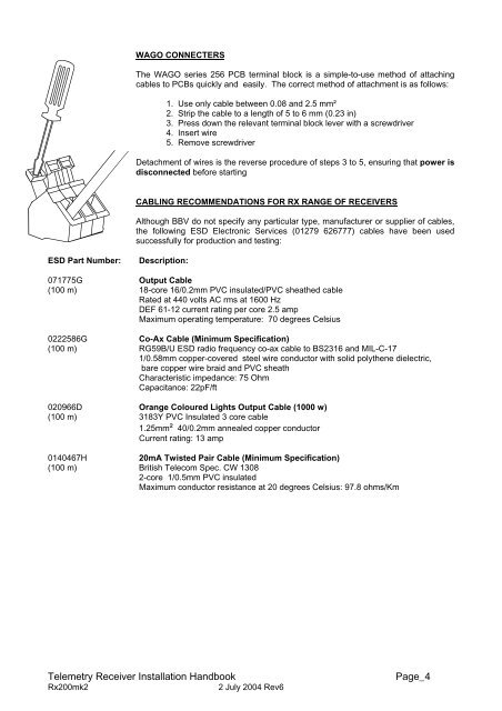
WAGO CONNECTERSThe WAGO series 256 PCB terminal block is a simple-to-use method of attachingcables to PCBs quickly and easily. The correct method of attachment is as follows:1. Use only cable between 0.08 and 2.5 mm²2. Strip the cable to a length of 5 to 6 mm (0.23 in)3. Press down the relevant terminal block lever with a screwdriver4. Insert wire5. Remove screwdriverDetachment of wires is the reverse procedure of steps 3 to 5, ensuring that power isdisconnected before startingCABLING RECOMMENDATIONS FOR RX RANGE OF RECEIVERSAlthough BBV do not specify any particular type, manufacturer or supplier of cables,the following ESD Electronic Services (01279 626777) cables have been usedsuccessfully for production and testing:ESD Part Number:Description:071775GOutput Cable(100 m) 18-core 16/0.2mm PVC insulated/PVC sheathed cableRated at 440 volts AC rms at 1600 HzDEF 61-12 current rating per core 2.5 ampMaximum operating temperature: 70 degrees Celsius0222586GCo-Ax Cable (Minimum Specification)(100 m) RG59B/U ESD radio frequency co-ax cable to BS2316 and MIL-C-171/0.58mm copper-covered steel wire conductor with solid polythene dielectric,bare copper wire braid and PVC sheathCharacteristic impedance: 75 OhmCapacitance: 22pF/ft020966D Orange Coloured Lights Output Cable (1000 w)(100 m) 3183Y PVC Insulated 3 core cable1.25mm² 40/0.2mm annealed copper conductorCurrent rating: 13 amp0140467H20mA Twisted Pair Cable (Minimum Specification)(100 m) British Telecom Spec. CW 13082-core 1/0.5mm PVC insulatedMaximum conductor resistance at 20 degrees Celsius: 97.8 ohms/KmTelemetry Receiver Installation HandbookRx200mk22 July 2004 Rev6Page_4
Rx200 INSTALLATION INSTRUCTIONSThe Rx200 requires all connections to the PCB to be made by the installer and via terminal blocks or by plugand socket. These connections are: power, video in, video out, and pan or auxiliary outputs. See Table forthe correct connections.The Rx200 is normally supplied pre-configured to suit the application for which it is intended, and this will beeither to control a mains-operated panning head or other equipment, or to control a 24-volt panning head.The unit is suitable for 230 volt mains operation. As a factory fitted option, the receiver can be supplied tooperate from 24Vac or 110Vac. This option must be specified at time of order.For mains-voltage panning heads, the 110Vac or 230Vac supply is made via the IEC socket J4 .(Note - for mains operations, J5 is supplied with a header which links Pins 1 to 4 and Pins 3 to 6. )When using 24Vac heads, if the receiver is operating from a 110Vac or 230Vac supply either a 230/24VacKit or 110/24Vac Kit is used. The jumper fitted to J5 is removed and the plug supplied with the kit isconnected to J5. Fuse F2 is changed to the value shown in the table on 2.Receivers operating from 24Vac can only operate 24Vac heads. No kit is required.When operating from a 24Vac supply, power connection is by means of a screw terminal replacing the IECsocket.An 8 way DIL switch is provided allowing various options to be set as follows:-SW1UnusedSW2Controls auto-iris remote control featuresON Cosmicar lens, 2.5 - 5.5 voltsOFF Seiko/Video Technical lens, 2.5 - 12 voltsSW3 and SW4 Select between WASHER or AUTOPANSW3 SW4 FunctionON ON WASHEROFF OFF AUTOPANSW5,6,7 UnusedSW8 Start receiver self test, see page 5.Two L.E.D.'s (Error and Cable) are mounted on-board to give simple system status information. Theirfunctions are as follows:-Cable LEDRegular Blinking - Telemetry and Sync signals OKBlinking but mainly ON - No telemetry information from the transmitterBlinking but mainly OFF - No sync information from the cameraError LEDOn - Transmission error (e.g. framing error, parity error)Both LED'sOff - No power, or major PCB errorAs all BBV equipment is designed to auto-tune and compensate for any discrepancies in the transmittersignal, there are no further adjustments that need to be made.Random PanThe Random Pan feature allows the receiver to drive the head in a left or right direction at random for arandom time. The head will pause for a random time between movements. Over a period of time, the headwill move between the right and left end stops. This feature does not require an autopan card to be fitted tothe head. The Random Pan is started by issuing a PATROL 1 command from the telemetry controller. Thekey strokes required will vary depending upon the model of controller. Please refer to the controllerhandbook for details.Telemetry Receiver Installation HandbookRx200mk22 July 2004 Rev6Page_5
- Page 3: Rx200 mk2AC Left/Right/Wipe/Lights/
- Page 7: LAUNCH AMPLIFIERThere are two varia
- Page 12 and 13: LAUNCH AMPLIFIERThere are two varia
- Page 15: 0222586GCo-Ax Cable (Minimum Specif
- Page 18 and 19: CABLE CONNECTIONS FOR Rx400P UNITSC
- Page 20 and 21: SW8(on/off) Start Self Test - LEFT,
- Page 22 and 23: 1. PRE-INSTALLATION CHECKS AND SAFE
- Page 24 and 25: Auto-Iris Output:Video Input:Video
- Page 26 and 27: 3. INSTALLATIONOPERATING VOLTAGEThe
- Page 28 and 29: 4. SETUPDIAGNOSTIC AIDSTwo L.E.D.
- Page 30 and 31: PROGRAMMING THE UNITProgramming is
- Page 32 and 33: SETTINGS FOR NORMAL OPERATIONSevera
- Page 34 and 35: INSTALLATION INSTRUCTIONS FOR PCB-B
- Page 36 and 37: BBV TX1500 exampleBuilding Block Vi
- Page 38 and 39: - This page is blank for your notes
- Page 40: The BBV product range.Product Descr
WAGO CONNECTERSThe WAGO series 256 PCB terminal block is a simple-to-use method of attachingcables to PCBs quickly and easily. The correct method of attachment is as follows:1. Use only cable between 0.08 and 2.5 mm²2. Strip the cable to a length of 5 to 6 mm (0.23 in)3. Press down the relevant terminal block lever with a screwdriver4. Insert wire5. Remove screwdriverDetachment of wires is the reverse procedure of steps 3 to 5, ensuring that power isdisconnected before startingCABLING RECOMMENDATIONS FOR RX RANGE OF RECEIVERSAlthough BBV do not specify any particular type, manufacturer or supplier of cables,the following ESD Electronic Services (01279 626777) cables have been usedsuccessfully for production and testing:ESD Part Number:Description:071775GOutput Cable(100 m) 18-core 16/0.2mm PVC insulated/PVC sheathed cableRated at 440 volts AC rms at 1600 HzDEF 61-12 current rating per core 2.5 ampMaximum operating temperature: 70 degrees Celsius0222586GCo-Ax Cable (Minimum Specification)(100 m) RG59B/U ESD radio frequency co-ax cable to BS2316 and MIL-C-171/0.58mm copper-covered steel wire conductor with solid polythene dielectric,bare copper wire braid and PVC sheathCharacteristic impedance: 75 OhmCapacitance: 22pF/ft020966D Orange Coloured Lights Output Cable (1000 w)(100 m) 3183Y PVC Insulated 3 core cable1.25mm² 40/0.2mm annealed copper conductorCurrent rating: 13 amp0140467H20mA Twisted Pair Cable (Minimum Specification)(100 m) British Telecom Spec. CW 13082-core 1/0.5mm PVC insulatedMaximum conductor resistance at 20 degrees Celsius: 97.8 ohms/KmTelemetry Receiver Installation HandbookRx200mk22 July 2004 Rev6Page_4


