Manual - Building Block Video CCTV
Manual - Building Block Video CCTV
Manual - Building Block Video CCTV
- No tags were found...

You also want an ePaper? Increase the reach of your titles
YUMPU automatically turns print PDFs into web optimized ePapers that Google loves.
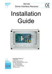
2. INTRODUCTIONGENERALThe Rx400DC receiver is designed to control DC-operated, high and variable speed pan/tilt heads anddomes.The Rx400DC receiver is supplied in an IP 67 rated enclosure. It will be necessary to make suitable holes inthe enclosure to permit cable entry and exit. Adequately rated cable glands and or flexible conduit should beused at all times to avoid compromising the protection afforded by the enclosure as supplied. Any holesmade in the enclosure for any other purpose should be sealed with a non-hardening water-proof sealant,taking care to ensure that the internal electronics are not contaminated.The Rx400DC receiver can be used with the Tx400DC single camera telemetry controller and with any of thefollowing BBV multi-camera telemetry transmitters, providing they are fitted with the DC option (joystick, highand variable speed):TX1000/8 TX1000/16 TX1000/8A TX1000/16A TX1500The slave keyboard Tx1000KBD can also be used, providing it is fitted with the DC option.Rx400DC TECHNICAL SPECIFICATIONPower Requirements: 230 volts 50Hz. IEC connector provided.Current Consumption:100VA maximumMaximum Load:5 Amp.Fuses: F1 Auxiliary fuse: 5A TF2 Receiver fuse: 630mA TFeatures:• 24VDC outputs suitable for high and variable speed pan/tilt heads.• Outputs for pan and tilt motor brakes as fitted to some DC pan/tilt heads.• 12 volt DC output suitable for cameras, etc. (500mAp. max. load).• 8 alarm inputs.• 1 N/C alarm output, with programmable delay.• Up to 16 full-scene pre-set positions can be stored within the Rx400DC.• On-board photocell suitable for switching up to 1kW of lighting.• Method of activating/controlling lighting output is programmable.• Fine-settable low-speed response and settable maximum speed.Engineering Facilities:• Unit auto-tunes to the coaxial telemetry signal.• LED readout for continual system status.• Self test feature activates each function for two seconds in turn. See Fig. 4, page11 for test sequence.• <strong>Video</strong> launch amplifier provided with Gain and Lift controls.• Colour-coded mains output terminal connections: Live, Neutral and EarthTelemetry Signals:Telemetry signals either:i) up the co-ax (designed to operate at 250M RG59/500M CT125);or ii) via twisted pair 20mA loop.Telemetry Receiver Installation HandbookRx400DC2 July 2004 Rev6Page_23