Manual - Building Block Video CCTV
Manual - Building Block Video CCTV
Manual - Building Block Video CCTV
- No tags were found...

Create successful ePaper yourself
Turn your PDF publications into a flip-book with our unique Google optimized e-Paper software.
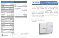
0222586GCo-Ax Cable (Minimum Specification)(100 m) RG59B/U ESD radio frequency co-ax cable to BS2316 and MIL-C-171/0.58mm copper-covered steel wire conductor with solid polythene dielectric,bare copper wire braid and PVC sheathCharacteristic impedance: 75 OhmCapacitance: 22pF/ft020966D Orange-Coloured Lights Output Cable (1000 w)(100 m) 3183Y PVC-insulated, 3-core cable1.25mm² 40/0.2mm annealed copper conductorCurrent rating: 13 amp0140467H20mA Twisted Pair Cable (Minimum Specification)(100 m) British Telecom spec CW 13082-core 1/0.5mm PVC-insulatedMaximum conductor resistance at 20 degrees Celsius: 97.8 ohms/kmLAUNCH AMPLIFIERThere are two variable controls, Lift and Gain, situated close to the BNC connector J1. These are preadjustedfor a cable distance of 250M, and are adjustable to compensate for video detail or signal losses ifand when longer or shorter cable lengths are used to connect the monitor to the receiver.Default Position. For shorter cable lengths, turn the relevant control anticlockwiseuntil the required picture quality is obtained. For longer cablelengths, turn the relevant control clockwise until the required picture clarity isobtained.The purpose of each control is:Lift: boosts the high-frequency signalGain: adjusts the gain of the video signalATTENTION:Ensure that the cable is terminated at the monitor end ONLYPRESETS ON THE Rx400PWhen using presets ensure correct connection of the feedback pots. Pay particular attention to ensuringthat power is not connected across one end of the pot and the wiper, as damage to the feedback pot mayensue.Beyond connecting the correct wiper to each function input, i.e. focus wiper to focus input etc. , the installerdoes not need to worry about reversing the polarity/direction of travel. If for instance the pan/tilt head hasbeen installed upside down, the receiver will compensate for this arrangement.Before using presets it is necessary to use the self test function, turn SW8 ONmomentarily. During the course of the self test the receiver senses the feedback potconnections. If the cabling/travel is reversed then the unit will reset the relevant directionbits within the receiver. Subsequent searches to preset should now function correctly.DO NOT PROGRAM PRESETS CLOSETO PHYSICAL ENDSTOPSTelemetry Receiver Installation HandbookRx400P mk22 July 2004 Rev6Page_15