Scissor Lift Manual - Titan Air
Scissor Lift Manual - Titan Air
Scissor Lift Manual - Titan Air

You also want an ePaper? Increase the reach of your titles
YUMPU automatically turns print PDFs into web optimized ePapers that Google loves.
SAFETY ALERTS!KNOW AND UNDERSTAND YOUR SAFETY SYMBOLS AND ALERTS!ACCIDENTS CAN BE AVOIDED, SAFETY IS VERY IMPORTANT TO US,IT SHOULD BE VERY IMPORTANT TO YOU!Follow instructions on safety tags on your equipment. Your safetyis of great concern, so please be alert to warnings, cautions andnotes. Labels on equipment and in this manual are intended tomake you aware of possible safety issues. When you see thissymbol, be alert to the possibility of personal injury or death.DANGER – Death, personal injury or property damage WILL be theresult if you fail to follow instructions.WARNING – Death, personal injury or property damage COULDbe the result if you fail to follow instructions.CAUTION – Damage to equipment COULD be the result if you failto follow instructions.NOTE – Information to further explain operations or instructions.2
FOREWORD<strong>Titan</strong> <strong>Air</strong> has manufactured the highest quality airmakeup systems since 1983 and has carried over thiscommitment to excellence in the manufacturing of personnellifts. Quality, technology and teamwork have enabled us to setstandards of excellence. We believe that our obligation to ourcustomers goes beyond providing them with a high qualityproduct. We must also provide the highest quality productsupport and warranty. We pledge to continue improvementsthrough the use of customer input and new technologies thatbecome available. As our valued customer, we realize that youhave come to expect nothing less.<strong>Manual</strong>s for <strong>Titan</strong> <strong>Lift</strong>s will be an on going andimproving process as we strive to supply the best featuresavailable.If we have overlooked something, if some information isincorrect, or if you have comments on printed material whichmay make our <strong>Titan</strong> <strong>Lift</strong> a better product, contact us. Youropinions do matter!3
TITAN SCISSOR LIFTSPECIFICATIONSANSI A92.6-1999 & OSHA Compliant Self-Propelled Elevating Work Platform1. X – AXIS TRAVEL – HORIZONTAL TRAVEL OF THE LIFT.The lift is driven by one aluminum wheel direct coupled to a hydraulicmotor. The hydraulic motor is driven by the hydraulic pump & air motorthat also powers the dual lift cylinder. The design speed in both directions is40 Ft. per minute. (See Figure 1 in Drawings & Photographs.)2. Y – AXIS ROLL OUT– HORIZONTAL TRAVEL OF BASKETThis lift is provided with a manual roll-out system. The basket is designedwith a secondary platform capable of moving out an additional 18”on theworking side of platform. The cantilevered deck moves in and out by pushingor pulling the secondary platform & locking the deck in either position withlocking pins provided on both sides of the hand rails.2. Z – AXIS TRAVEL – VERTICAL TRAVEL OF BASKETThe maximum vertical travel of the lift basket from floor to basket floor is9 Ft. 6in.The lift travel is accomplished by means of a hydraulic pump driven by anair motor. (See Figure 2 in Drawings & Photographs.) The hydraulic pumpdrives the dual cylinders which in-turn raises the scissor lift platform. Thedescent of the platform is gravity descent and velocity fuses provided on bothcylinders prevent uncontrolled drop in the event of a hose failure. The rate ofspeed is designed at 15 ft. per minute.4. OPERATOR BASKET CONTROLSThe control panel for basket movement is located on the front (door side) ofthe basket. The controls are “joy stick” valves that are moved in thedirection of desired travel and will spring return to stopped position whenreleased. The Emergency Down valve is included to lower the basket in theevent of an air supply loss. The E-Down valve is located at the unit baseopposite the ground control. Ground control is also provided to allow theraising or lowering the basket from ground level (see photograph).5. UTILITIESEach <strong>Titan</strong> <strong>Lift</strong> requires an air supply of 80 CFM at 100 PSI of clean, dryair. All internal components are provided with the lift and only one point ofconnection is required. The internal components include all of the piping,tubing, valves, hydraulic/pneumatic switches, filter/regulator/lubricator andsafety lock-out valve for required maintenance. The single air supply sourcewill be provided through a festooning system.4
TITAN SCISSOR LIFTOPERATIONAL INSTRUCTIONSALL OPERATING AND MAINTENANCE PERSONNEL MUST BE TRAINEDON THE TITAN LIFT.1. The basket has a total maximum weight capacity of 600 pounds with the rolloutretracted or extended.2. Connect the air supply hose to the air mast once installed. The mast has asleeve welded to the top for supporting the air hose coming from thefestooning to prevent hose from excessive bending or kinking.3. With the air supply connected, slowly open the main air supply shutoff valve(See Figure 4 in Drawings & Photographs). Once the air supply is turned on,confirm the air pressure air regulator is set at 100 PSI. The lift is then ready tooperate. Make sure the lubricator has been filled.4. There are two locking devices on each side of the basket (See Figure 6 inDrawings & Photographs). Both of these locking devices must be engaged ineither the retracted or extended position.5. The operator must stay in the basket with the spring loaded access doorcompletely closed and the roll out locking device engaged on both sides ofbasket. When entering the basket, it is very important to have the lockingdevices engaged to prevent the basket roll out from moving out.6. Operating the basket – the lift is very simple to operate. The axis movement iscontrolled by the respective “joystick” and in the direction of desired travelwhich is vertical travel (UP/DOWN) or horizontal travel (LEFT/RIGHT) thismovement is labeled on the respective “joystick (See Figure 5 in Drawings &Photographs). When the basket has reached full travel or stroke, the basketwill stop.7. OTHER LIFT CONTROLSa. EMERGENCY STOP – The e-stop is located on the basket control paneland ground control. These e-stops will shut off the air supply to all axiscontrols. This is a simple push/pull button (red). Push to activate andpull to reset (See Figure 5 in Drawings & Photographs).b. EMERGENCY DOWN – This control valve allows the basket to belowered when the main air supply to the lift is interrupted. Thiscontrol is activated by simply turning the valve counterclockwise.After the lift is fully lowered, close the valve by turning it clockwise.(See Figure 7 in Drawings & Photographs.)c. SAFETY SHUT OFF VALVE – The lift is equipped with a lockablesafety shut off valve which will turn off the air supply to the unit. Thiswill completely disable the <strong>Titan</strong> <strong>Lift</strong> which will allow the requiredmaintenance or repairs. Rotate the valve handle 90 degrees orperpendicular to air flow.d. This will exhaust all air pressure from the system. It is recommendedthat lockout/tag out procedures be followed.e. During maintenance and when the lift is raised, it is very important toinstall a block between the lower arm cam roller & the end of the camway channel to prevent the scissors arms from moving. These blocksshould be installed on both sides of frame.7
TITAN SCISSOR LIFTSAFETYSafety is the single most important feature that must be taken into considerationwhen developing, manufacturing and operating a product. <strong>Titan</strong> has taken manyprecautions to assure that the product offered is the safest it can be. It should be noted thata machine can be the safest in the world but if the operator does not operate or maintain itproperly, the safety that has been built into the machine will be compromised.The following is a list of DO’S and DON’TS that must be followed:DO read the operation and maintenance manual completely prior to operating the lift forthe first time.DO use care, caution, and common sense when operating your <strong>Titan</strong> lift.DO check all lifting clearance.DO use safety devices at all times. Leave all guards and screens in place.DO use caution and relieve the pressure before opening any pressurized system or lines.DO remember that failure to follow safety precautions could result in injury or death.DO periodically clean warning labels and replace them if they become damaged.DO start and maintain a regular maintenance program. Failure to do so will reduce the lifespan of the lift.DO NOT attempt to get off the lift unless it is in the fully lowered and retracted position.DO NOT operate the lift if it is damaged or not running properly.DO NOT place over 600 pounds (This includes lift operator) in the standard basket and DONOT attempt to service the lift unless it is fully lowered and air supply is shut off. (If liftmust be raised for service, the assembly MUST be securely supported, so it can not descend)DO NOT allow the lift to become excessively dirty. Periodically clean off paint over sprayand/or debris that may accumulate.8
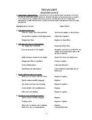
TITAN SCISSOR LIFTMAINTENANCE1. TROUBLE SHOOTING – YOUR TITAN LIFT IS DESIGNED AND BUILT TO GIVEYEARS OF TROUBLE FREE SERVICE. HOWEVER, BECAUSE MECHANICAL PARTSCAN AND DO FAIL, PROBLEMS MAY OCCUR. LISTED BELOW IS A TROUBLESHOOTING GUIDE WHICH WILL ASSIST IN DIAGNOSIS AND RESOLUTION TO THEPROBLEM.PROBLEM & CAUSE1. <strong>Lift</strong> Will Not Operate.Main air supply off or line pinched.<strong>Air</strong> pressure regulator needs adjustment.Base or basket E-Stop depressedSystem Control key is offPlugged air filter.2. <strong>Lift</strong> Operates Slow or Intermittent.<strong>Air</strong> supply line is pinched.Low air pressure or air supplyHigh moisture content in air supply.Plugged air filter or mufflers.Lack of lubrication.Insufficient air lubrication.3. Basket Will Not Move Vertically.Z-axis shuttle valve malfunction.Pilot valve not shifting<strong>Air</strong> Motor not turningHydraulic Pump not operatingSOLUTIONTurn on air supply or check hoses.Adjust air regulator.Reset E-StopTurn key to ON positionReplace or clean filter.Inspected all air lines.Regulator must be set at 100 PSI- <strong>Air</strong>supply must consistently deliver 80SCFM at 100 PSI.Inspect air dryer on compressor.Clean or replace.Lubricate all zerks.Check fluid level and drip rate oflubricator.Replace.Check for pilot air pressureRepair or replaceReplace <strong>Air</strong> MotorCheck Coupling between air motorReplace hydraulic pump9
TITAN SCISSOR LIFTMAINTENANCE4. Erratic or Loss of Vertical Control.Leaking valve.Pilot valve or shuttle valve sticking.5. Basket Will Not Descend.Descend flow control set abovevelocity fuse ratingLoss of pilot air pressureRepair or replace.Replace.Decrease flow control settingCheck for air flow to down valvefrom main panel6. Slow or Erratic Movement Along RailsRails obstructed or rail joints not smooth.Hydraulic motor coupling disengagedHydraulic motor not functioningClean rails or grind rail joints.Replace couplingReplace hydraulic motor7. Basket Roll Out Will Not Extend or Retract.Inspect mast bearings on roll outReplace if necessaryLocking pins not fully retracted8. Unit Continues to Run After Release of “Joy Stick”Joy Stick handle is stickingReplace or repairJoy Stick valve is by-passingJoy Stick valve exhaust port muffleris pluggedHydraulic unit air motor pilot valveis stickingBase control valves are sticking orby passing.ReplaceClean or replaceClean or replaceReplace10
TITAN SCISSOR LIFTMAINTENANCE9. <strong>Air</strong> Motor Not Running or Running SlowMotor temperature excessively hot.Motor will not run.Lack of lubrication.Check air supply/muffler.Check lubrication.Replace motor.Runs normally then slows. Confirm 100 PSI air pressure and 80CFM. Defective air motor/replace.Low Torque.Low Speed.Lack of lubrication,misalignment, internalcorrosion, inadequate airpressure.Lack of lubrication,misalignment, internalcorrosion, inadequate airpressure.11
TITAN SCISSOR LIFT2. GENERAL MAINTENANCE INFORMATIONA. FILTER/REGULATORA combination filter/regulator is installed in the base of the unit which filtersout contamination and small amounts of moisture from the air supply (See Figure 8in Drawings & Photographs). This device is equipped with an automatic float valveto drain off normal amounts of moisture. However, if there is too much moisture inthe air, the customer will need to install a dryer in the supply line that is feeding theunit. The regulator should be set at 100 PSI.B. AIR LUBRICATORAll pneumatic components in the <strong>Titan</strong> <strong>Lift</strong> are lubricated by an oil mistlubricator that is installed in the lower base of the unit after the filter/regulator(SeeFigure 8 in Drawings &Photographs). The oil level should be checked daily andrefilled when necessary. The oil mist is important for two reasons: 1. Lubricationand 2. Prevention of surface rust on internal components such as valves and airmotors. Whenever adding oil to the lubricator the air supply must be shut off anddrained by turning off the safety lockout valve in the unit base (See Figure 4 inDrawings & Photographs). Only good quality air tool oil should be used in thelubricator. If air tool oil is not available, use high quality petroleum based oil with aviscosity of 150-200 SSU at 100 deg. F. (Equivalent to SAE #10). Because some oilshave additives which damage pneumatic components never substitute another typeof oil. The oil delivery setting on the lubricator of 2 drops per minute is present atthe factory and should not need readjustment. The rate can be checked by countingthe number of drops of oil per minute in the feed sight dome.C. ALUMINUM DRIVE WHEELIn order to reduce the possibility of sparking in an explosiveenvironment, the drive wheels are made of aluminum. These wheels should beinspected periodically for damage or wear and replaced when excessive wear isevident.D. SAFETY STOPSThe <strong>Titan</strong> <strong>Lift</strong> is equipped with a safety device to prevent uncontrolleddescent of the basket. The hydraulic cylinders will lock instantaneously in positionshould a hose break or fail in some manner. This is caused by velocity fuses installeddirectly to the ports on the cylinders.12
TITAN SCISSOR LIFTH. SUGGESTED PREVENTATIVE MAINTENANCE PROGRAMITEM QTY MAINTENANCE REQUIRED FREQUENCYLubricator 1 Check level and fill as needed DailyHydraulic Unit Check oil level WeeklyDrive wheel flange 2 Grease Fittings(until excess 1000 Hoursbearings.shows)Drive wheel coupling 1 Inspect for signs of wear 120 HoursAluminum drivewheel2 Inspect for sign of excessive wear,replace as needed1000 HoursFastenersCheck for loose fasteners, tighten 1000as neededHosesVisually inspect for wear or 1000damage, replace as neededDecals Clean or replace if necessary As neededCleaningRemove dirt & paint buildup, As neededrelube as neededExhaust Valves Replace As needed<strong>Air</strong> Motor Mufflers Replace As needed13
TITAN LIFT WARRANTY 12/04<strong>Titan</strong> <strong>Air</strong> Inc. hereby warrants its products against defects in materialand workmanship for a period of (13) thirteen months from date ofshipment.<strong>Titan</strong> <strong>Air</strong> Inc. reserves the right to replace or repair free of charge, anypart proven by <strong>Titan</strong> <strong>Air</strong> Inc. to be defective. Prompt notification ofdefective part must be provided to <strong>Titan</strong> <strong>Air</strong> Inc. and the defective partmust be returned freight prepaid within (30) thirty days of notification.(<strong>Air</strong> mufflers not covered by warranty)Warranty includes only parts supplied by <strong>Titan</strong> <strong>Air</strong> Inc. Incidental costsand labor charges shall be the responsibility of others.Locally purchased parts will not be reimbursed w/o <strong>Titan</strong> <strong>Air</strong> Inc. priorapproval.All warranty parts are to be obtained from <strong>Titan</strong> <strong>Air</strong> Inc.This warranty is void if attempts to correct or repair any allegeddefective part or parts are made by unauthorized personnel without<strong>Titan</strong> <strong>Air</strong> Inc. written approval.In no event shall <strong>Titan</strong> <strong>Air</strong> Inc. be held liable for any damage, incidentalor consequential, arising from the installation, performance oroperation of the product.This warranty supersedes, voids and/or is in lieu of any other verbal orwritten understanding which may not be in total accordance with thisexpressed warranty.14
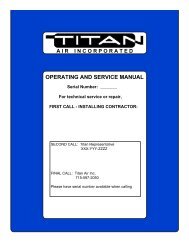
TITAN LIFTPARTS RETURN POLICYAll warranty parts are to be obtained from <strong>Titan</strong> <strong>Air</strong> Inc.Locally purchased parts will not be reimbursed.When ordering replacement parts, it is important to have the followinginformation available:1. Serial number of the lift (This is on the lift ID plate).2. Part number or description of part needed.3. Explanation of failure/defect.4. Complete shipping and billing instructions.a.) Ship to address.b.) Shipping method desired (Regular UPS, Next day airetc.)c.) Billing address including your purchase order number.d.) A warranty tag will accompany the replacement part.The customer shall fill out the information requiredon the tag and return it with the defective part.e.) The defective part with return tag must be returned to<strong>Titan</strong> <strong>Air</strong> Inc. prepaid within 30 days to receive credit.You will be billed for the part(s) immediately. Credit will be issued forwarranty parts after the defective part(s) have been returned to thefactory.15
VALVESDESCRIPTION/FUNCTIONTITAN SCISSOR LIFTTITAN CROSS REFERENCE PART NO. AND DESCRIPTIONSUGGESTED SPARE PARTS CUSTOM SCISSOR LIFTLOCATIONT I T A NPT. NO.FLOOR MOUNTED MANUAL UP/DOWNCONTROL LOWER BASE 4-06-50-00352 2CONTROL AIR SUPPLY VALVE CONTROL PANEL 4-06-50-00357 1SYSTEM CONTROL ON/OFF VALVE GROUND CONTROL 5-06-50-00821 1BASE & OPERATORE-STOPCONTROL PANEL 4-06-50-00358 2SHUTTLE VALVE BASE CONTROL 4-06-50-00351 2LOCKABLE BALL VALVEBASE CONTROLMAIN AIR SUPPLY 5—06-50-00827 1JOY STICK CONTROL X-Z AXISOPERATORCONTROL PANEL 4-06-50-00356 2HYDRAULIC UNIT MOTOR VALVE BASE 5-06-50-00822 1QTY/LIFTBEARINGSMAST GUIDE BEARING – ROLL OUT BASKET BASE 5-06-60-00737 4DRIVE WHEEL FLANGE BRG. BASE ASSEMBLY 5-06-01-00803 4SCISSORS ARM BEARING LOWER SCISSORS ARM 5-06-80-00669 2SCISSORS ARM BEARING UPPER SCOSSORS ARM 4-06-20-00043 2MUFFLERSAIR EXHAUST MUFFLERS E-Stop & Sys Control 4-06-50-00217 3Joy-Stick Controls 5-06-50-00818 4<strong>Air</strong> Supply Valve 4-06-50-00346 1Hydraulic Unit <strong>Air</strong>Motor Valve 4-06-50-00349 2Base Hydraulic Mtr. 5-06-50-00828 1HYDRAULIC CYLINDERRAISE/LOWER PLATFORM BASE FRAME 5-06-50-00695 2WHEELS NON-DRIVENPHENOLIC BASE 5-06-00638 2WHEELS NON-DRIVEN/DRIVENALUMINUM DRIVE SIDE BASE 5-04-01-00632 2COUPLINGHUB FOR HYD MOTOR IN BASE 5-06-01-00701 2COUPLING SPIDER IN BASE 5-06-01-00702 1HYDRAULIC MOTOR LIFT BASE 5-06-01-00640 1HYDRAULIC PUMP PACKAGE LIFT BASE 5-06-50-00802 116
AI R M O T OR S MOTOR HYD. PACK 5-06-50-00801 1FILTER/REG/LUBRICATORBASE 4-06-50-00127 1BASE 4-06-50-00126 1Quick clamp BASE 4-06-50-00128 2Quick clamp & wall bracket BASE 4-06-50-00129 2Quick Exhaust Pipe Adaptor BASE 4-06-50-00328 2Porting Block BASE 5-06-50-00820 1LINE/HOSE TRACK SCISSORS ARMS 4-06-55-00829 34-06-55-00830 34-06-55-00831 18 FT17
TITAN SCISSOR LIFTREFERENCE DRAWINGS/PHOTOGRAPHSAluminumWheelHydraulicMotorCouplingFigure 1<strong>Air</strong>MotorHydraulicPumpFigure 218
<strong>Air</strong> ChamberMastBolt <strong>Air</strong> ChamberMast to base andfasten back crossbeam<strong>Air</strong> ChamberMastNote:See “<strong>Air</strong> Hose MastLocation Drawing formore details on how toorientate lifts in booth.Bolt <strong>Air</strong> ChamberMast to base andfasten back crossbeamFigure 319
<strong>Air</strong> SupplyShut-Off ValveFigure 4Left/RightEmergencyStopUp/DownFigure 520