Manual - ABOVE GROUND POOLS, inflatables, ready to use - INTEX
Manual - ABOVE GROUND POOLS, inflatables, ready to use - INTEX
Manual - ABOVE GROUND POOLS, inflatables, ready to use - INTEX

You also want an ePaper? Increase the reach of your titles
YUMPU automatically turns print PDFs into web optimized ePapers that Google loves.
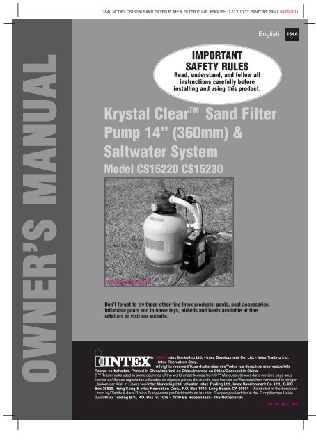
(164) MODEL CS15220 SAND FILTER PUMP & FILTER PUMP ENGLISH 7.5” X 10.3” PANTONE 295U 08/09/2011English164AOWNER’S MANUALIMPORTANTSAFETY RULESRead, understand, and follow allinstructions carefully beforeinstalling and using this product.Krystal Clear TM Sand FilterPump 14” (360mm) &Saltwater SystemModel CS15220 CS15230For illustrative purposes only.Don’t forget <strong>to</strong> try these other fine Intex products: pools, pool accessories,inflatable pools and in-home <strong>to</strong>ys, airbeds and boats available at fineretailers or visit our website.©2011 Intex Marketing Ltd. - Intex Development Co. Ltd. - Intex Trading Ltd.- Intex Recreation Corp.All rights reserved/Tous droits réservés/Todos los derechos reservados/AlleRechte vorbehalten. Printed in China/Imprimé en Chine/Impreso en China/Gedruckt in China.® Trademarks <strong>use</strong>d in some countries of the world under license from/® Marques utilisées dans certains pays souslicence de/Marcas registradas utilizadas en algunos países del mundo bajo licencia de/Warenzeichen verwendet in einigenLändern der Welt in Lizenz von/Intex Marketing Ltd. <strong>to</strong>/à/a/an Intex Trading Ltd., Intex Development Co. Ltd., G.P.OBox 28829, Hong Kong & Intex Recreation Corp., P.O. Box 1440, Long Beach, CA 90801 • Distributed in the EuropeanUnion by/Distribué dans lʼUnion Européenne par/Distribuido en la unión Europea por/Vertrieb in der Europäischen Uniondurch/Intex Trading B.V., P.O. Box nr. 1075 – 4700 BB Roosendaal – The Netherlands164-*A*-R0-1208
(164) MODEL CS15220 SAND FILTER PUMP & FILTER PUMP ENGLISH 7.5” X 10.3” PANTONE 295U 08/09/2011English164AWarnings.......................................................................... 3Parts List & References.................................................. 4-8Setup Instructions ......................................................... 9-16Product Specifications................................................... 11Operating Instructions .................................................. 17-21LED Code Chart.............................................................. 22Intex Pools Salt Table...................................................... 23Intex Pools Operating Time Table ................................. 24Intex Pools Cyanuric Acid Table.................................... 25Non-Intex Pools Salt Table.............................................. 26Non-Intex Pools Operating Time Table.......................... 26Non-Intex Pools Cyanuric Acid Table............................ 26Maintenance.................................................................... 27-31Long Term S<strong>to</strong>rage.......................................................... 31TABLE OF CONTENTSTroubleshooting Guide................................................... 32-34Common Pool Problems................................................. 35General Aquatic Safety................................................... 36Limited Warranty............................................................. 37Intex Service Center Locations..................................... 38SAVE THESE INSTRUCTIONS Page 2
(164) MODEL CS15220 SAND FILTER PUMP & FILTER PUMP ENGLISH 7.5” X 10.3” PANTONE 295U 08/09/2011English164APARTS LIST (continued)22 232425 26 2728 29 30PARTS LIST31 32 3334 35 36Optional37 38 39OptionalOptional4041NOTE: Drawings for illustration purpose only. Actual product may vary. Not <strong>to</strong> scale.SAVE THESE INSTRUCTIONS Page 5
(164) MODEL CS15220 SAND FILTER PUMP & FILTER PUMP ENGLISH 7.5” X 10.3” PANTONE 295U 08/09/2011English164APARTS REFERENCE (continued)Before assembling your product, please take a few minutes <strong>to</strong> check the contentsand become familiar with all the parts.2829282930 31 32 33 3430 31 32 3330 35 36 37PARTS REFERENCE282930 35 36 382829NOTE: Drawings for illustration purpose only. Actual product may vary. Not <strong>to</strong> scale.SAVE THESE INSTRUCTIONS Page 7
(164) MODEL CS15220 SAND FILTER PUMP & FILTER PUMP ENGLISH 7.5” X 10.3” PANTONE 295U 08/09/2011English164APARTS REFERENCE (continued)Before assembling your product, please take a few minutes <strong>to</strong> check the contentsand become familiar with all the parts.REF. NO. DESCRIPTION QTY. SPARE PART NO.1 PRESSURE GAUGE 1 114112 6-WAY VALVE SET 1 113783 DRAIN OUTLET COVER 1 111314 TANK O-RING 1 113795 SCREW 2 113816 CLAMP 1 113807 SAND SHIELD 1 113828 CENTER PIPE HUB 1 113839 DRAIN VALVE CAP 1 1145610 DRAIN VALVE O-RING 1 1138511 LATERAL 10 1138412 HOSE WITH NUTS 2 1101013 SAND FILTER INTERCONNECTING HOSE 1 1139014 LEAF TRAP NUT 1 1147915 LEAF TRAP O-RING 1 1123216 BASKET 1 1126017 FILTER HOUSING NUT 1 1126118 L-SHAPE O-RING 4 1122819 SEDIMENT RELEASE VALVE 1 1046020 VALVE O-RING 1 1026421 FLOW SENSOR 1 1146022 ELECTROLYTIC CELL 1 1137223 TITANIUM ELECTRODE 1 1138924 COPPER ELECTRODE 1 1123425 PRE-FILTER ASSEMBLY 1 1137126 PUMP MOTOR & CONTROL 1 11466/11466BS27 L-SHAPE O-RING 1 1143928 PLUNGER VALVE (HOSE O-RING & STEP WASHER INCLUDED) 2 1074729 HOSE O-RING 2 1026230 STEP WASHER 2 1074531 STRAINER NUT 2 1025632 FLAT STRAINER RUBBER WASHER 2 1025533 THREADED STRAINER CONNECTOR 2 1123534 ADJUSTABLE POOL INLET NOZZLE 1 1107435 ADAPTOR B 2 1072236 STRAINER CONNECTOR 2 1107037 POOL INLET NOZZLE 1 1107138 STRAINER GRID 1 1107239 CHLORINE TEST STRIPS 1 1963540 COPPER TEST STRIPS 1 1125441 LEAF TRAP COVER 1 11480PARTS REFERENCEWhen ordering parts, be sure <strong>to</strong> quote the model number and part numbers.SAVE THESE INSTRUCTIONS Page 8
(164) MODEL CS15220 SAND FILTER PUMP & FILTER PUMP ENGLISH 7.5” X 10.3” PANTONE 295U 08/09/2011English164APOOL OUTLET - STRAINER & PLUNGER VALVE SETUPThe strainer grid prevents large objects from jamming and/or damaging thefilter pump. If your pool has an inflatable <strong>to</strong>p ring, install the strainer, nozzleand plunger valve before inflating the pool liner <strong>to</strong>p ring. The part numbershere onward refer <strong>to</strong> the parts depicted in the Parts List section of thismanual. To install, do the following:1. In a counter-clockwise motion unscrewplunger valve union from the threadedstrainer connec<strong>to</strong>r (33) (see drawing 1).Be careful not <strong>to</strong> lose the step rubberwasher (30). Place the plunger valve onthe ground in a safe place.2. In a counter-clockwise motion unscrew thestrainer nut (31) from the threadedconnec<strong>to</strong>r (33). Leave the flat washer (32)on the connec<strong>to</strong>r (33).3. Install the strainer and plunger valve at thelower position of pool outlet (marked "+").From the inside of the pool liner insert theconnec<strong>to</strong>r (33) in<strong>to</strong> one of the pre-cut holeswith the washer remaining on theconnec<strong>to</strong>r <strong>to</strong> be placed against the insideof the liner wall.4. Before assembly, lubricate the threads witha petroleum jelly. With the flat side of thestrainer nut (31) facing the outside wall ofthe liner in a clockwise motion screw thestrainer nut (31) back on<strong>to</strong> the threadedconnec<strong>to</strong>r (33) (see drawing 2).5. Finger tighten the strainer nut (31) on<strong>to</strong> thethreaded connec<strong>to</strong>r (33).6. Grasp the plunger valve assembly. Makesure the step washer (30) is in place.7. In a clockwise motion screw the plungervalve union back on<strong>to</strong> the threadedconnec<strong>to</strong>r (33) (see drawing 3).8. Examine the plunger valve <strong>to</strong> see if thehandle is pushed fully down <strong>to</strong> the "0/1"position. If not, then grasp the handle atthe <strong>to</strong>p and push down turning the handlein a clockwise direction until the plasticprotruding notch anchors in the "0/1"position. This will prevent water fromflowing out during filling (seedrawings 4.1 & 4.2).3112212INSIDELINER WALL32 33130INSIDELINERWALL1234.14.2SETUP INSTRUCTIONSSAVE THESE INSTRUCTIONS Page 9
(164) MODEL CS15220 SAND FILTER PUMP & FILTER PUMP ENGLISH 7.5” X 10.3” PANTONE 295U 08/09/2011English164APRODUCT SPECIFICATIONSThe sand filter removes suspended particles and sanitize your pool. Poolchemistry is a specialized area and you should consult your local poolservice specialist for details.Power:220-240 Volt ACWattage:470 WIdeal Salt Level:3000 ppm (parts per million)Maximum Sanitizer Output/hour: 10 grams/hourCopper Ionizer Output Current: 175mAMaximum working pressure:2.4 bar (35 psi)Effective filtering area: 0.1 m 2 (1.1 ft 2 )Maximum Flow Rate:6050 liters/hour (1600 gallons/hour)Recommended filtering media:No. 20 silica sand or glass sand. Particle size(Not included)range 0.45 <strong>to</strong> 0.85 mm (0.018 <strong>to</strong> 0.033 inches).Uniformity Coefficient less than 1.75.Recommended filtering media quantity: No. 20 silica sand 25 Kg (55 Lbs) or glass sand18 Kg (40 Lbs).Limited Warranty:see “Limited Warranty”SETUP INSTRUCTIONSTOOLS REQUIRED: One (1) Phillips screwdriverPump location and mounting:• The system must be installed on a solid level and vibration-free base.• Provide a location protected from the weather, moisture, flooding andfreezing temperature.• Provide adequate access, space and lighting for routine maintenance.• Pump mo<strong>to</strong>r requires free circulation of air for cooling. Do not installthe pump in a damp or non-ventilated location.A team of 2 or more people is recommended for setting up this product.Mo<strong>to</strong>r pre-filtering assembly setup:1. Remove the sand filter and its accessoriesfrom the packaging carefully and inspect forany visible damage. If parts are damagedcontact your local service center listed at theback of this ownerʼs manual.2. In a counter-clockwise motion unscrew the leaftrap cover (14) from the pre-filter housing. Takeout the basket (16) and filter housing nut (17)(see drawing 10).3. Connect the pre-filter housing <strong>to</strong> the mo<strong>to</strong>rwater inlet. Note: Align the connec<strong>to</strong>r in thepre-filter housing with the water inlet on themo<strong>to</strong>r (see drawing 11).144116171011PRODUCT SPECS & SETUP INSTRUCTIONSSAVE THESE INSTRUCTIONS Page 11
(164) MODEL CS15220 SAND FILTER PUMP & FILTER PUMP ENGLISH 7.5” X 10.3” PANTONE 295U 08/09/2011English164ASETUP INSTRUCTIONS (continued)4. In a clockwise motion screw filter housing nut (17) on<strong>to</strong> the mo<strong>to</strong>r water inlet(See drawings 12.1 & 12.2).12.112.25. Replace the basket (16) and leaf trap cover (14) back <strong>to</strong> the pre-filter housing(See drawings 13.1 & 13.2).14411713.1 13.216Sand tank installation:1. Place the tank support base at the selected location.2. Place the tank on the tank support base (See drawing 14.1).3. Connect the mo<strong>to</strong>r pre-filtering assembly unit <strong>to</strong> the tank support base (Seedrawing 14.2). NOTE: Ensure the pre-filter housing water inlet hose connectionis facing <strong>to</strong>wards the pool.IMPORTANT: Some countries, especially in the European community,require the product <strong>to</strong> be secured <strong>to</strong> the ground or <strong>to</strong> a base in apermanent upright position. Check your local authorities <strong>to</strong> determine ifthere is a regulation in your area regarding above-the-ground swimmingpool filter-pumps. If yes, then the product can be mounted <strong>to</strong> a platformusing the two holes located in the base. See drawing 14.3.The product can be mounted on a cement base or on<strong>to</strong> a woodenplatform <strong>to</strong> prevent accidental falling over.• The mounting holes are 6.4 mm in diameter and spaced 160 mmapart.• Use two bolts and lock nuts with a maximum of 6.4 mm in diameter.17SETUP INSTRUCTIONS14.1 14.214.3160mmSAVE THESE INSTRUCTIONS Page 12
(164) MODEL CS15220 SAND FILTER PUMP & FILTER PUMP ENGLISH 7.5” X 10.3” PANTONE 295U 08/09/2011English164ASETUP INSTRUCTIONS (continued)Sand loading:IMPORTANT: Use No. 20 silica sand or glass sand with particle size range0.45 <strong>to</strong> 0.85 mm (0.018 <strong>to</strong> 0.033 inches) and a Uniformity Coefficient lessthan 1.75.NOTE: Before loading the tank with sand, ensure the center pipe hubassembly is securely in place at the bot<strong>to</strong>m of the tank, and verticallycentered inside the tank.1. Place the sand shield (7) over the <strong>to</strong>p of the center pipe. Pour the sand in<strong>to</strong> thetank at a slow rate. (see drawing 15).2. Fill the tank approximately half way, remove the sand shield (7). (seedrawing 16).15 1673. Evenly distribute the sand inside the tank, then fill the tank with some water <strong>to</strong>provide a cushioning effect when the remaining sand is poured in. Thisprevents the center pipe hub (8) from excessive shock (see drawing 17).Place the sand shield (7) back and continue <strong>to</strong> pour the sand in<strong>to</strong> the tank.4. Sand shall be filled between the “MAX” and “MIN” marked gauge on the centerpipe. Evenly spread and level out the sand by hand (see drawings 17 & 18).8717 18SETUP INSTRUCTIONSMAX8MAXMINMINMAXMIN5. Remove the sand shield (7).6. Wash away all sand around the <strong>to</strong>p edge of the tank.SAVE THESE INSTRUCTIONS Page 13
(164) MODEL CS15220 SAND FILTER PUMP & FILTER PUMP ENGLISH 7.5” X 10.3” PANTONE 295U 08/09/2011English164ASETUP INSTRUCTIONS (continued)WARNINGImproper tank valve and clamp assembly could ca<strong>use</strong> the valve and clamp<strong>to</strong> blow off and ca<strong>use</strong> serious injury, property damage or death.6-way valve installation:1. Lower the 6-way valve over the tank slowly, and ensure the bypass pipe protrudingunderneath the 6-way valve fits securely in<strong>to</strong> the center pipe hub (8) <strong>to</strong>p opening (seedrawing 19).IMPORTANT: There are three hose connection ports on the 6-way valve, ensurethe outlet connection (from filter <strong>to</strong> the pool) on the valve is facing <strong>to</strong>wards thepool, and the inlet connection (from mo<strong>to</strong>r <strong>to</strong> valve) is aligned with the mo<strong>to</strong>routlet (see drawing 20).2. Remove the clamp bolt, and install the clamp around the tank and 6-way valve flanges,then replace the clamp bolt and <strong>use</strong> a phillips screwdriver (not included) <strong>to</strong> tighten it.(see drawing 21).19 WATER2021INLETWATEROUTLET3. Connect the sand filter interconnecting hose (13) between the 6-way valve inlet andmo<strong>to</strong>r outlet, and insert the electrolytic cell (22) in<strong>to</strong> the 6-way valve outlet. Hand tightenthem securely (see drawings 22 and 23).13822 236SETUP INSTRUCTIONS224. Screw and tighten the flow sensor (21) <strong>to</strong> the electrolytic cell (22), then plug in theelectrolytic cell line cord and tighten the nut (see drawings 24 and 25).2124 2522SAVE THESE INSTRUCTIONS Page 14
(164) MODEL CS15220 SAND FILTER PUMP & FILTER PUMP ENGLISH 7.5” X 10.3” PANTONE 295U 08/09/2011English164ASAND FILTER PUMP HOSE CONNECTION SETUPWARNING• Keep this product more than 2m away from the pool.• Keep this product more than 3.5m away from the pool (for France only).• Keep the plug of this product more than 3.5m away from the pool.• Position this product away from the pool, so as <strong>to</strong> prevent children fromclimbing on it and accessing the pool.The 6-way valve has three hose connection ports.1. Connect one hose (12) end <strong>to</strong> the pre-filter inlet and the other end of the hose<strong>to</strong> the lower plunger valve with the strainer. Ensure the hose nuts are securelytightened.2. Connect the second hose (12) between the electrolytic cell outlet and theupper plunger valve with the inlet-nozzle. Ensure the hose nuts are securelytighten.3. The third hose connection port (drain/waste outlet) on the 6-way valve shall bedirected <strong>to</strong> a proper draining receptacle using a hose or pipe (not provided).Remove the drain cap before attaching the drain/waste hose or pipe.4. The sand filter pump is now <strong>ready</strong> <strong>to</strong> filter the pool.TODRAIN6-WAY VALVEPLUNGERVALVEWATER LEVELADJUSTABLEPOOL INLETNOZZLETHREADEDSTRAINERCONNECTORSETUP INSTRUCTIONSOUTSIDELINER WALL>2M>3.5M(ILLUSTRATION NOT TO SCALE)SAVE THESE INSTRUCTIONS Page 15
(164) MODEL CS15220 SAND FILTER PUMP & FILTER PUMP ENGLISH 7.5” X 10.3” PANTONE 295U 08/09/2011English164ASAND FILTER PUMP HOSE CONNECTION SETUP (continued)For NON-<strong>INTEX</strong> pool:1. Connect the hose (12) <strong>to</strong> the pool inlet/outlet connection with a large hoseclamp. Tighten securely. Remove the drain valve (3) from the 6-way valveoutlet and connect the hose <strong>to</strong> the outlet.312LARGE HOSECLAMPPOOLFor <strong>INTEX</strong> pool size 16' and below:1. In a counter-clockwise motion unscrew plunger valve union from the threadedstrainer connec<strong>to</strong>r (25). Be careful not <strong>to</strong> lose the step rubber washer (22).2. Grasp the plunger valve assembly. Make sure the step washer (22) is in place.Connect adap<strong>to</strong>r B (27) <strong>to</strong> plunger valve union.3. Remove wall plug and then insert the strainer (28 & 30) in<strong>to</strong> the lower positionof protruding hose connection, and the nozzle (28 & 29) in<strong>to</strong> the upper positionof protruding hose connection. Adap<strong>to</strong>r B (27) fits over the strainerconnection (28) inserted in<strong>to</strong> the connection. Tighten securely.4. Remove the drain valve (3) from the 6-way valve outlet and connect the hose<strong>to</strong> the outlet.SETUP INSTRUCTIONS28 & 293 28 & 30<strong>POOLS</strong>AVE THESE INSTRUCTIONS Page 16
FILTERRINSERINSE(164) MODEL CS15220 SAND FILTER PUMP & FILTER PUMP ENGLISH 7.5” X 10.3” PANTONE 295U 08/09/2011English164AOPERATING INSTRUCTIONS• Risk of electric shock. Connect this product only <strong>to</strong> a grounding typereceptacle protected by a ground-fault circuit interrupter (GFCI) orresidual current device (RCD). Contact a qualified electrician if you cannotverify that the receptacle is protected by a GFCI/RCD. Use a qualifiedelectrician <strong>to</strong> install the GFCI/RCD, which has a maximum rate of 30mA.Do not <strong>use</strong> a portable residual current device (PRCD).• To reduce the risk of electric shock, do not <strong>use</strong> extension cords, timers,plug adap<strong>to</strong>rs or converter plugs <strong>to</strong> connect unit <strong>to</strong> electric supply;provide a properly located outlet.• Do not attempt <strong>to</strong> plug in or unplug this product while standing in wateror when your hands are wet.• Never operate this product above the maximum working pressure statedon the filter tank.• Always switch off pump before changing the 6-way valve position.• Operating this product without water flowing through the system canca<strong>use</strong> a build up of hazardous pressure which can result in an explosivesituation, serious injury, property damage or death.• Never test this pump with compressed air. Never operate the system withwater temperature above 35° C (95° F).Valve Position Function Water Flow DirectionFILTER(see drawing 27)Normal filtration and regularvacuuming of poolFrom pump through filter media<strong>to</strong> poolBACKWASH(see drawing 28)Reverses water flow <strong>to</strong> cleanfilter mediaFrom pump through filter media<strong>to</strong> valve waste/drain outletRINSE(see drawing 29)For initial startup cleaning of the sand, andleveling the sand bed after backwashingFrom pump through filter media<strong>to</strong> valve waste/drain outletWASTE(see drawing 30)RECIRCULATE(see drawing 31)CLOSED(see drawing 32)WARNING6-way valve positions and function:For vacuuming directly <strong>to</strong> waste,lowering pool level or <strong>to</strong> drain the poolFor circulating water back <strong>to</strong> poolwithout going through the filter mediaShuts off all flow <strong>to</strong> filter and pool“Do not <strong>use</strong> this setting with pump running”27From pump <strong>to</strong> valve waste/drainoutlet bypassing the filter mediaFrom pump through valve <strong>to</strong>pool bypassing the filter media2829OPERATING INSTRUCTIONSRECIRCULATERINSEFILTERCLOSEWASTERECIRCULATERINSEBACKWASHCLOSEWASTERECIRCULATERECIRCULATEBRINSEFILTERCLOSEBRINSEBACKWASHFILTERWASTESAVE THESE INSTRUCTIONS Page 17REBACKWEWASTEWASTERECIRCULATERINSEBACKWASHCLOSEWASTERECIRCULATERECIRCULATEBACKWASHCLOSERINSEFILTERWASTEBACKWASHRINSEFILTERRECIRCRINSEFILTERRECIRCULATERESTEWASTERECIRCULATERINSEBACKWASHFILTERWASTEFILTERRECIRCULARINSEFILTERRINSEERRECIRCULATEWASTEFILTERFILTER
ECIRCULATEBCLOSEWASTERECIRCULATERECIRCULATERINSEBACKWASHBFILTERCLOSECLOSEWASTEWASTELATEBACKWASHCLOSEWASTRECIRCULATEINSE(164) MODEL CS15220 SAND FILTER PUMP & FILTER PUMP ENGLISH 7.5” X 10.3” PANTONE 295U 08/09/2011BACKWASHCLOSEWASTERECIRCULATERINSEBACKWASHFILTERWASTERECIRCULATEBACKWASHWASTERECIRCULATERINSEFILTERBACKWASHEnglish164ARERINSEBACKWASHFILTERCLOSEWASTERERINSERECIRCULATEBACKWASHRINSEBACKWASHOPERATING INSTRUCTIONS (continued)FILTERCLOSEWASTEFILTERCLOSE30Initial startup and operation:Before operating, be sure that:• All the hoses have been connected and tightened securely, and correct amoun<strong>to</strong>f filter sand have been loaded.• The entire system is connected <strong>to</strong> a grounding type receptacle protected by aground-fault circuit interrupter (GFCI) or residual current device (RCD).CAUTIONThe filter control valve has a closed position. The pump should never beon when the valve is in the closed position. If the pump is operated withthe valve closed, and explosive situation could exist.1. Grasp a plunger valve handle. Turn the handle counter-clockwise, pull up until its<strong>to</strong>ps, and then turn it clockwise until the metal protruding notch anchor is inthe "0/1" position. Repeat for the second plunger valve. This opens the valves <strong>to</strong>allow water <strong>to</strong> flow in<strong>to</strong> the sand filter pump.2. Ensure the drain/waste outlet on the 6-way valve is not covered and directed <strong>to</strong>a proper draining receptacle.3. Ensure the pump is off, depress the 6-wayvalve and turn it <strong>to</strong> the “BACKWASH” position(see drawings 28 & 33).IMPORTANT: To prevent damage <strong>to</strong> the6-way valve, always depress the valvehandle before turning. Always switch offpump before changing the 6-way valveposition.4. Switch on the pump (see drawing 34). Wateris circulating backward through the sandmedia and <strong>to</strong> waste/drain outlet. Backwashuntil a clear flow of water is observed in thewaste/drain outlet or through the drain sedimentwindow.NOTE: The initial backwash of the filter isrecommended <strong>to</strong> remove any impurities or finesand particles in the sand media.RECIRCULATERINSEBACKWASHFILTERCLOSE31RECIRCULATERINSEBACKWASHON2FILTERCLOSEOFFRECIRCULATEBACKWASHFILTERCLOSEWASTE1323334RECIRCULATEOPERATING INSTRUCTIONSWASTEBACKWASHFILTERCLOSERECIRCULATEBACKWASHSAVE THESE INSTRUCTIONS Page 18
(164) MODEL CS15220 SAND FILTER PUMP & FILTER PUMP ENGLISH 7.5” X 10.3” PANTONE 295U 08/09/2011English164AOPERATING INSTRUCTIONS (continued)5. Switch off the pump, change the 6-way valve <strong>to</strong> “RINSE” position (seedrawing 29).6. Switch on the pump and run the pump for about one minute <strong>to</strong> level out thesand bed after backwashing the sand media.7. Switch off the pump, change the 6-way valve <strong>to</strong> “FILTER” position (seedrawing 27).8. Switch on the pump. The system is now operating in the normal filtering mode.Run the pump until the desired pool water clearance is obtained and no morethan 12 hours per day.9. Record the initial pressure gauge reading when the filter media is clean.NOTE: During initial setup of the system, it may be necessary <strong>to</strong> backwashfrequently due <strong>to</strong> unusual heavy dirt present in the water and sand. After that,as the filter removes dirt and impurities from the pool water, the accumulateddirt in the sand media will ca<strong>use</strong> the pressure <strong>to</strong> rise and the flow <strong>to</strong> diminish. Ifthere is no vacuuming device attached <strong>to</strong> the system and the pressure gaugereading is in the yellow zone it is time <strong>to</strong> backwash the sand media, see“BACKWASH” under “initial startup and operation” section.Vacuuming device (i.e. Intex au<strong>to</strong> pool cleaner) attached <strong>to</strong> the system may alsoca<strong>use</strong> the flow <strong>to</strong> diminish and the pressure <strong>to</strong> rise. Remove any vacuumingdevice from the system and check if the pressure gauge reading has droppedfrom the yellow zone <strong>to</strong> the green zone.OPERATING INSTRUCTIONSSAVE THESE INSTRUCTIONS Page 19
(164) MODEL CS15220 SAND FILTER PUMP & FILTER PUMP ENGLISH 7.5” X 10.3” PANTONE 295U 08/09/2011English164ASALTWATER SYSTEM OPERATION1. Start up the unit:Plug the power cord in<strong>to</strong> the electrical outlet and testthe GFCI/RCD (circuit breaker). Switch on the unit.With the Filter Pump turned “ON” and operating.Flashing code“00” appears on the electronic controlstationʼs LED, indicating that the unit is <strong>ready</strong> <strong>to</strong> beprogrammed.2. Set operating hours for Saltwater System:With code “00” flashing, press but<strong>to</strong>n <strong>to</strong>set the desired operating hours. See the“Operating Time Table” for the requiredoperating hours related <strong>to</strong> each pool size.Pressing will increase the time from 01<strong>to</strong> 12 hours maximum. If you have selected<strong>to</strong>o many hours keep pressing <strong>to</strong> repeatthe cycle. The built-in timer will now activateyour Saltwater System, at the same time (1 <strong>to</strong> 12 hours max per cycle)each day, for the number of hours you have set.NOTE: The Saltwater System will not operate if the filter pump is not operating.3. Lock keypad controls:With the desired hour value showing, press but<strong>to</strong>n untilyou hear a “beep”. The green “WORKING” indica<strong>to</strong>r on thecontrol panel will light up within a few seconds <strong>to</strong> indicate thatthe saltwater system has started sanitizer production. Lockingthe control but<strong>to</strong>ns in<strong>to</strong> this setting prevents unauthorizedchanging of the operating cycle.NOTE: If you forget <strong>to</strong> lock the keypad controls, the system willau<strong>to</strong>matically lock it and start working 1 minute later.4. Readjust operating time if necessary:The operating hours can be re-adjusted if necessary.Press but<strong>to</strong>n until you hear a “beep” <strong>to</strong> unlock thekeypad and the current programmed time will flash.Repeat steps 2 <strong>to</strong> 3.5. Test the copper concentration in thepool water.The Saltwater System recommends a copper level of 0.1 <strong>to</strong> 0.2 ppm.This is easily tested by the copper ion test strips provided. If the test result is0.1~0.2ppm, go directly <strong>to</strong> step 7.0Copper (ppm)0.1 0.2 0.5 0.9 1.3OPERATING INSTRUCTIONSOKSAVE THESE INSTRUCTIONS Page 20
(164) MODEL CS15220 SAND FILTER PUMP & FILTER PUMP ENGLISH 7.5” X 10.3” PANTONE 295U 08/09/2011English164ASALTWATER SYSTEM OPERATION (continued)6. Boost cycle• If the test result is below 0.1ppm, press and hold “BOOST”but<strong>to</strong>n for 5 seconds until the indica<strong>to</strong>r lights up and theLED display display “80”. This indicates that the saltwatersystem has started copper ion and more chlorine sanitizerproduction. You can press and hold the “BOOST” but<strong>to</strong>n foranother 5 seconds until the indica<strong>to</strong>r is off, which will cancelthe Boost cycle.Note: Once the system has started copper ion and morechlorine sanitizer production, the boost but<strong>to</strong>n canʼt be re-set until the powerswitch is off.• The boost operating hours is 4 times the amount of time programmed in<strong>to</strong> thesystem, i.e. if your saltwater system operating time is 2 hours, the boost procedurewill run 4 x 2 = 8 hours. After boost procedure has been completed, the systemwill au<strong>to</strong>matically switch <strong>to</strong> the normal working mode.• After a heavy rain or if the pool is dirty, press the “BOOST” but<strong>to</strong>n <strong>to</strong> shock thepool again.7. Test pool water regularly:Once the copper level appears <strong>to</strong> be balanced, test the pool water every week<strong>to</strong> maintain the proper sanitizer level.Itʼs very important that the free chlorine is between 0.4-1.5 ppm and copperion concentration is between 0.1~0.2 ppm. When the copper level is below 0.1ppm, repeat step 6.NOTE: A High copper ion concentration may ca<strong>use</strong> blonde hair <strong>to</strong> exhibit agreen hair. To prevent this, wear a swimming cap during swimming, and washhair with special shampoo after using the pool.See “Troubleshooting Guide”.8. Stand-by/power saving mode:• When the cycle ends, the green “SLEEP” indica<strong>to</strong>r on thecontrol panel lights up and the LED display flashes “93”.The system is now in Stand-By mode. After a while, itshuts down and sets itself in a Power Saving mode. Thesystem will au<strong>to</strong>matically turn itself back on in 24 hours,starting its daily cycle of chlorine production.• The “SLEEP” indica<strong>to</strong>r stays on, while the system is in thePower Saving mode. The LED display however, goes blankafter 1 hour. Press any but<strong>to</strong>n ( or ) <strong>to</strong> view the last LEDcode.9. Running the pump alone without the Saltwater System:To run the pump alone without the Saltwater System function,press and hold both ( ) and ( ) but<strong>to</strong>ns for 5 secondsuntil you hear a “beep” and the LED display shows “FP”.The pump is now operating alone. To s<strong>to</strong>p the pump,manually turn the switch OFF. NOTE: The pump cannotbe operated alone under an au<strong>to</strong>matic timer mode.OPERATING INSTRUCTIONSIMPORTANT: To keep the initial au<strong>to</strong>matic operating cyclesetting of the Saltwater System, turn the switch ON, theLED display shows “FP”, then unlock and lock the keypadcontrols again, see previous steps 2 and 3. The LED displayshows the initial input hours and the Saltwater System cycle repeats again.SAVE THESE INSTRUCTIONS Page 21
(164) MODEL CS15220 SAND FILTER PUMP & FILTER PUMP ENGLISH 7.5” X 10.3” PANTONE 295U 08/09/2011English164ALED ReadingFPLED CODE CHARTDefinitionsFilter Pump Working Mode80 Boost Mode00 Stand-By Mode (Start-up)01 Minimum Operating Hour (1 hour remaining)02 Operating Hours (2 hours remaining)03 Operating Hours (3 hours remaining)04 Operating Hours (4 hours remaining)05 Operating Hours (5 hours remaining)06 Operating Hours (6 hours remaining)07 Operating Hours (7 hours remaining)08 Operating Hours (8 hours remaining)09 Operating Hours (9 hours remaining)10 Operating Hours (10 hours remaining)11 Operating Hours (11 hours remaining)12 Maximum Operating Hours (12 hours remaining)90 Alarm Code (Low Water Flow / No Flow)91 Alarm Code (Low Salt Level)92 Alarm Code (High Salt Level)93 Stand-By Mode (Operating Process finished)“BLANK”No Power or “Power Saving Mode” waiting <strong>to</strong> start nextSaltwater System cycle.LED CODE CHARTSAVE THESE INSTRUCTIONS Page 22
(164) MODEL CS15220 SAND FILTER PUMP & FILTER PUMP ENGLISH 7.5” X 10.3” PANTONE 295U 08/09/2011English164A<strong>INTEX</strong> <strong>POOLS</strong> SALT TABLEThis table shows the dosage of salt needed <strong>to</strong> achieve and maintain the optimal 3000 ppm saltlevel.Pool Size<strong>INTEX</strong> <strong>ABOVE</strong> <strong>GROUND</strong> <strong>POOLS</strong> (AGPʼs)EASY SET ®POOLCIRCULARMETALFRAME POOLULTRA FRAME<strong>POOLS</strong>EQUOIA SPIRITPOOL SETOVAL FRAMEPOOLRECT. ULTRAFRAME POOL15' x 33" (457cm x 84cm)15' x 36" (457cm x 91cm)15' x 42" (457cm x 107cm)15' x 48" (457cm x 122cm)16' x 42" (488cm x 107cm)16' x 48" (488cm x 122cm)18' x 42" (549cm x 107cm)18' x 48" (549cm x 122cm)18' x 52" (549cm x 132cm)15' x 36" (457cm x 91cm)15' x 42" (457cm x 107cm)15' x 48" (457cm x 122cm)16' x 48" (488cm x 122cm)18' x 48" (549cm x 122cm)18' x 52" (549cm x 132cm)20' x 52" (610cm x 132cm)24' x 48" (732cm x 122cm)16' x 48" (488cm x 122cm)18' x 52" (549cm x 132cm)16'8" x 49" (508cm x 124cm)18'8" x 53" (569cm x 135cm)18' x 10' x 42" (549cm x 305cm x 107cm)20' x 12' x 48" (610cm x 366cm x 122cm)24' x 12' x 48" (732cm x 366cm x 122cm)18' x 9' x 52" (549cm x 274cm x 132cm)24' x 12' x 52" (732cm x 366cm x 132cm)Water Capacity (Calculated at90% for Frame Pool and 80%for Easy Set & Oval Pool)Salt Needed forStartup3.0g/L (3000ppm)Salt Needed whenLow Salt Detected(CODE “91”)(Gals) (Liters) (Lbs) (Kgs) (Lbs) (Kgs)2587 9792 65 30 15 102822 10681 65 30 20 103284 12430 80 35 20 103736 14141 95 45 25 103754 14209 95 45 25 104273 16173 110 50 30 154786 18115 120 55 30 155455 20647 135 60 35 155894 22309 150 65 40 203282 12422 80 35 20 103861 14614 100 45 25 104440 16805 110 50 30 155061 19156 125 55 35 156423 24311 160 75 40 206981 26423 175 80 45 208638 32695 220 100 60 2511483 43462 290 130 75 355061 19156 125 55 35 156981 26423 175 80 45 205061 19156 125 55 35 156981 26423 175 80 45 202885 10920 65 30 20 104393 16628 110 50 30 155407 20465 135 60 35 154545 17203 115 50 30 158403 31805 210 100 55 25SAVE THESE INSTRUCTIONS Page 23
(164) MODEL CS15220 SAND FILTER PUMP & FILTER PUMP ENGLISH 7.5” X 10.3” PANTONE 295U 08/09/2011English164A<strong>INTEX</strong> <strong>POOLS</strong> OPERATING TIME TABLE (WITH CYANURIC ACID)Pool Size<strong>INTEX</strong> <strong>ABOVE</strong> <strong>GROUND</strong> <strong>POOLS</strong> (AGPʼs)EASY SET ®POOLCIRCULARMETALFRAME POOLULTRA FRAME ®<strong>POOLS</strong>EQUOIA SPIRIT ®POOL SETOVAL FRAMEPOOLRECT. ULTRAFRAME POOL15' x 33" (457cm x 84cm)15' x 36" (457cm x 91cm)15' x 42" (457cm x 107cm)15' x 48" (457cm x 122cm)16' x 42" (488cm x 107cm)16' x 48" (488cm x 122cm)18' x 42" (549cm x 107cm)18' x 48" (549cm x 122cm)18' x 52" (549cm x 132cm)15' x 36" (457cm x 91cm)15' x 42" (457cm x 107cm)15' x 48" (457cm x 122cm)16' x 48" (488cm x 122cm)18' x 48" (549cm x 122cm)18' x 52" (549cm x 132cm)20' x 52" (610cm x 132cm)24' x 48" (732cm x 122cm)16' x 48" (488cm x 122cm)18' x 52" (549cm x 132cm)16'8" x 49" (508cm x 124cm)18'8" x 53" (569cm x 135cm)18' x 10' x 42" (549cm x 305cm x 107cm)20' x 12' x 48" (610cm x 366cm x 122cm)24' x 12' x 48" (732cm x 366cm x 122cm)18' x 9' x 52" (549cm x 274cm x 132cm)24' x 12' x 52" (732cm x 366cm x 132cm)Water Capacity (Calculated at90% for Frame Pool and 80% forEasy Set & Oval Pool)(Gals)258728223284373637544273478654555894328238614440506164236981863811483506169815061698128854393540745458403(Liters)979210681124301414114209161731811520647223091242214614168051915624311264233269543462191562642319156264231092016628204651720331805Operating Time (hours)at different ambient/airtemperatures10 - 19°C(50 - 66°F)1112222331223344734341232520 - 28°C(68 - 82°F)1122233331233445734341333529 - 36°C(84 - 97°F)22233334423345568454523436SAVE THESE INSTRUCTIONS Page 24
(164) MODEL CS15220 SAND FILTER PUMP & FILTER PUMP ENGLISH 7.5” X 10.3” PANTONE 295U 08/09/2011English164A<strong>INTEX</strong> <strong>POOLS</strong> CYANURIC ACID TABLECyanuric acid is a chemical that reduces the loss of chlorine in water due <strong>to</strong> ultraviolet rays. Tomaintain maximum performance, we recommend that the cyanuric acid level be maintained atapproximately 1% of the salt, i.e. 100 Lbs (45 Kgs) salt x1% = 1 Lbs (0.45 Kgs) cyanuric acid.Pool Size<strong>INTEX</strong> <strong>ABOVE</strong> <strong>GROUND</strong> <strong>POOLS</strong> (AGPʼs)15' x 33" (457cm x 84cm)15' x 36" (457cm x 91cm)15' x 42" (457cm x 107cm)EASY SET ®15' x 48" (457cm x 122cm)16' x 42" (488cm x 107cm)POOL16' x 48" (488cm x 122cm)18' x 42" (549cm x 107cm)18' x 48" (549cm x 122cm)18' x 52" (549cm x 132cm)15' x 36" (457cm x 91cm)15' x 42" (457cm x 107cm)15' x 48" (457cm x 122cm)CIRCULAR16' x 48" (488cm x 122cm)METALFRAME POOL18' x 48" (549cm x 122cm)18' x 52" (549cm x 132cm)20' x 52" (610cm x 132cm)24' x 48" (732cm x 122cm)ULTRA FRAME ® 16' x 48" (488cm x 122cm)POOL18' x 52" (549cm x 132cm)SEQUOIA SPIRIT ® 16'8" x 49" (508cm x 124cm)POOL SET18'8" x 53" (569cm x 135cm)18' x 10' x 42" (549cm x 305cm x 107cm)OVAL FRAME20' x 12' x 48" (610cm x 366cm x 122cm)POOL24' x 12' x 48" (732cm x 366cm x 122cm)RECT. ULTRA 18' x 9' x 52" (549cm x 274cm x 132cm)FRAME POOL 24' x 12' x 52" (732cm x 366cm x 132cm)Water Capacity (Calculated at90% for Frame Pool and 80%for Easy Set & Oval Pool)Cyanuric Acid Needed forStartup0.03g/L (30ppm)(Gals) (Liters) (Lbs) (Kgs)2587 9792 0.6 0.32822 10681 0.7 0.33284 12430 0.8 0.43736 14141 0.9 0.43754 14209 0.9 0.44273 16173 1.1 0.54786 18115 1.2 0.55455 20647 1.4 0.65894 22309 1.5 0.73282 12422 0.8 0.43861 14614 1.0 0.44440 16805 1.1 0.55061 19156 1.3 0.66423 24311 1.6 0.76981 26423 1.7 0.88638 32695 2.2 1.011483 43462 2.9 1.35061 19156 1.3 0.66981 26423 1.7 0.85061 19156 1.3 0.66981 26423 1.7 0.82885 10920 0.7 0.34393 16628 1.1 0.55407 20465 1.4 0.64545 17203 1.1 0.58403 31805 2.1 1.0SAVE THESE INSTRUCTIONS Page 25
(164) MODEL CS15220 SAND FILTER PUMP & FILTER PUMP ENGLISH 7.5” X 10.3” PANTONE 295U 08/09/2011English164ASALT CALCULATION FORMULA FOR ALL <strong>POOLS</strong>Salt Needed for Startup(Lbs)Salt Needed for Startup(Kgs)Salt Needed whenLow Salt Detected (Lbs)Salt Needed whenLow Salt Detected (Kgs)Water Capacity (Gals) x 0.025 Water Capacity (Liters) x 0.003 Water Capacity (Gals) x 0.0067 Water Capacity (Liters) x 0.0008SALT TABLE FOR COMMON NON-<strong>INTEX</strong> <strong>POOLS</strong>Water CapacitySalt Needed for StartupSalt Needed whenLow Salt Detected(CODE “91”)(Gals) (Liters) (Lbs) (Kgs) (Lbs) (Kgs)2000 7500 50 20 10 54000 15000 100 45 25 106000 22500 150 65 40 208000 30000 200 90 55 2510000 37500 250 110 70 3012000 45500 300 135 80 3514000 53000 350 160 95 45OPERATING TIME TABLE FOR COMMON NON-<strong>INTEX</strong> <strong>POOLS</strong>(Gals)2000400060008000100001200014000Water Capacity(Liters)750015000225003000037500455005300010 - 19°C(50 - 66°F)1235679Operating Time (hours)at different ambient/air temperatures20 - 28°C(68 - 82°F)123568929 - 36°C(84 - 97°F)13467910CYANURIC ACID TABLE FOR COMMON NON-<strong>INTEX</strong> <strong>POOLS</strong>Water CapacityCyanuric Acid Needed for Startup0.03g/L (30ppm)(Gals) (Liters) (Lbs) (Kgs)200040006000800010000120001400075001500022500300003750045500530000.51.01.52.02.53.03.50.230.450.680.901.131.371.59SAVE THESE INSTRUCTIONS Page 26
(164) MODEL CS15220 SAND FILTER PUMP & FILTER PUMP ENGLISH 7.5” X 10.3” PANTONE 295U 08/09/2011English164AMOTOR PRE-FILTER CLEANING AND MAINTENANCE1. Make sure the filter pump is switched off, then disconnect the power cord fromthe electrical outlet.2. Grasp a plunger valve handle. Turn the handle counter-clockwise, push downuntil it s<strong>to</strong>ps and then turn it clockwise until the plastic protruding notch anchorsin the "0/1" position. Repeat for the second plunger valve. This prevents thewater from flowing out of the pool.3. Release the pressure first by opening the35sediment release valve (19) locatedon the lower side of the pre-filter housing(see drawing 35).194. In a counter-clockwise motion unscrew theleaf trap cover (14), then remove thebasket (16) and leaf trap o-ring (15) from the2pre-filter housing (see drawing 36).15. Empty and flush the basket using a gardenhose, may <strong>use</strong> a plastic brush <strong>to</strong> remove36deposits from the basket. Do not <strong>use</strong> metal 14brush.41156. Clean and rinse the inside of the pre-filterhousing and the leaf trap O-ring with16a garden hose.7. Reinstall the leaf trap O-ring, basket and leaftrap cover <strong>to</strong> the pre-filter housing.8. Close the sediment release valve (19) back.MAINTENANCEFLOW SENSOR CLEANING1. In a counter-clockwise motion unscrew the collar of the flow sensor (21)and remove it from the electrolytic cell conduit (22). See “Part Reference”.2. If deposits and debris are seen on the surface of the flow sensor, then <strong>use</strong>a garden hose <strong>to</strong> wash it off.HingeLoca<strong>to</strong>r NotchConnection Ridge3. If flushing with water does not remove the deposits, <strong>use</strong> a plastic brush <strong>to</strong>clean the surface and the hinge if necessary. Do not <strong>use</strong> a metal brush.4. After the flow sensor has been inspected and cleaned, align the loca<strong>to</strong>rnotch on the flow sensor <strong>to</strong> the connection ridge in the conduit. Now turnthe collar in a clockwise motion, tightening the sensor back in<strong>to</strong> its position.Do not overtighten.SAVE THESE INSTRUCTIONS Page 27
(164) MODEL CS15220 SAND FILTER PUMP & FILTER PUMP ENGLISH 7.5” X 10.3” PANTONE 295U 08/09/2011English164AELECTROLYTIC CELL CLEANINGIf the pool water is hard (high mineral content) the cell may require periodic manualcleaning. To maintain maximum performance, we recommend that you open andvisually inspect the electrolytic cell (22) once every month.The following steps are some instructions on how <strong>to</strong> clean your cell.1. Switch off the unit, unplug the power cord from the electrical socket.2. Disconnect the hose (12) from the electrolytic cell (22) outlet and cover theoutlet with the drain outlet cover (3) from the 6-way valve (see drawings 37and 38).3. Remove the electrolytic cell from the 6-way valve outlet by unscrewing theelectrolytic cell (22) collar (see drawing 39).4. Pour kitchen grade vinegar in<strong>to</strong> the cell <strong>to</strong> immerse the titanium plates (seedrawing 40). Soak for about 1 hour and then flush with a high-pressuregarden hose.5. Reverse steps 2 <strong>to</strong> 4 <strong>to</strong> reconnect the electrolytic cell.37 38 394022322MAINTENANCECOPPER ELECTRODE CLEANING1. Switch off the unit, unplug the power cord from the electrical socket.2. In a counter-clockwise motion, unscrew the electrical plug collar from thecopper electrode cell, and remove the electrical plug from electrode cell (seedrawings 41 and 42).3. Unscrew the copper electrode cell collar, then remove the electrode cell andplace it on a bucket.4. Pour kitchen grade vinegar in<strong>to</strong> the bucket until the copper electrode cell isimmersed (see drawing 44). Soak for 1 hour and then flush with ahigh-pressure garden hose.5. Reverse steps 2 <strong>to</strong> 4 <strong>to</strong> reconnect the copper electrode cell.2441 42 4344SAVE THESE INSTRUCTIONS Page 28
(164) MODEL CS15220 SAND FILTER PUMP & FILTER PUMP ENGLISH 7.5” X 10.3” PANTONE 295U 08/09/2011English164AMAINTENANCE (continued)<strong>INTEX</strong> ® COPPER ION TEST STRIPS (PACKED WITH THE PRODUCT)The Copper Ion Test Strips can be <strong>use</strong>d <strong>to</strong> test the copper ion concentration in the water.Directions and Use1. Dip the entire strip in<strong>to</strong> the water for 3 seconds, then remove it.2. Hold the strip level for 15 seconds. Do not shake excess water from the strip.3. Now compare the copper ion strip pad <strong>to</strong> the color chart on the packaging label.<strong>INTEX</strong> ® 3-WAY TEST STRIPS (PACKED WITH THE PRODUCT)The 3-Way Test Strips can test the “Free Chlorine”, “pH”, and “Total Alkalinity” levels at thesame time. We recommend that you test the water chemistry weekly, and maintain thechlorine concentration at 0.4-1.5 ppm.Directions and Use1. Dip the entire strip in<strong>to</strong> the water and remove immediately.2. Hold the strip level for 15 seconds. Do not shake excess water from the strip.3. Now compare the strip pad <strong>to</strong> the color chart on the packaging label. If necessary,adjust the chemical level in the pool water. It is very important, <strong>to</strong> <strong>use</strong> the propertechnique when testing the water's chemical level. Read and follow the written stripinstructions carefully.MAINTENANCEPOOL CARE & CHEMICALS• All pools require care <strong>to</strong> keep the water clear and hygienically clean. With properchemical control, your filter will help attain this objective. Consult your pool supply dealerfor instructions regarding the proper <strong>use</strong> of chlorine, algaecide and other chemicalagents required for sparkling clear water.• Keep pool chemicals away from children.• Do not replenish chemicals in pool while pool is occupied. Skin or eye irritations couldoccur.• Daily pH checking and chemical treatment of the water is very important and cannot beoveremphasized. Maintenance of proper pH levels are required when filling the pool aswell as during the season. Consult your local swimming pool supply s<strong>to</strong>re forinstructions.• The season's first filling of the pool may have brackish water requiring extra wateradditives and extra filtering time. Do not allow swimming in pool until the pH level isbalanced. Consult your local swimming pool supply s<strong>to</strong>re for instructions.• Chlorinated water may damage lawns, gardens or shrubbery as children play in the pooland splash water outside the pool. Lawn areas underneath the pool liner will bedestroyed. Note that some types of grass may grow through the liner.• Filter run time depends on pool size, weather and usage level. Experiment with variousrun times so as <strong>to</strong> produce clean clear water.SAVE THESE INSTRUCTIONS Page 29
(164) MODEL CS15220 SAND FILTER PUMP & FILTER PUMP ENGLISH 7.5” X 10.3” PANTONE 295U 08/09/2011English164APOOL MAINTENANCE & CHEMICAL DEFINITIONSPreferred Water Chemistry ReadingMinimum Ideal MaximumCopper Ions 0 0.1 - 0.2 ppm 0.2 ppmFree Chlorine 0 0.4 - 1.5 ppm 3.0 ppmCombined Chlorine 0 0 ppm 0.2 ppmpH 7.2 7.4 - 7.6 7.8Total Alkalinity 100 ppm 100 - 140 ppm 140 ppmCalcium Hardness 150 ppm 200 - 400 ppm 500 - 1000 ppmStabilizer (Cyanuric Acid) 10 ppm 30 - 50 ppm 100 ppmConsult with local swimming pool dealer for water treatment.Free Chlorine -Combined Chlorine -Is the chlorine residual present in pool water.Is formed by the reaction of free chlorine with ammoniawastes.Result if <strong>to</strong>o high - Sharp chlorinous odor, eye irritation.pH - A value that indicates how acidic or basic a solution is.Result if <strong>to</strong>o low - Corroded metals, eye & skin irritation,destruction of <strong>to</strong>tal alkalinity.Result if <strong>to</strong>o high - Scale formation, cloudy water, shorterfilter runs, eye & skin irritation, poorchlorine efficiency.MAINTENANCETotal Alkalinity -Calcium Hardness -Stabilizer -(Cyanuric Acid)Indicates the degree of the water's resistance <strong>to</strong> changein pH. It determines the speed and ease of pH change,so always adjust <strong>to</strong>tal alkalinity before adjusting the pHlevel.Result if <strong>to</strong>o low -Result if <strong>to</strong>o high -Corroded metals, eye & skin irritation.Low alkalinity will ca<strong>use</strong> the pH <strong>to</strong> beunstable. Any chemical added <strong>to</strong> thewater will have an affect on pH.Scale formation, cloudy water,eye & skin irritation, poor chlorineefficiency.Refers <strong>to</strong> the amount of calcium and magnesiumdissolved in the water.Result if <strong>to</strong>o high - Scale will form and will ca<strong>use</strong> thewater <strong>to</strong> become cloudy.Stabilizers extend the life of chlorine in swimming pools.• Do not add pool chemicals directly <strong>to</strong> the skimmer. This may damage the cell.• Maintaining a salt and sanitizer level above the recommended range cancontribute <strong>to</strong> the corrosion of the pool equipment.• Check the expiry date of the test kit as the test results may be inaccurate if thekit is <strong>use</strong>d after that date.• If, due <strong>to</strong> heavy pool usage, it is required <strong>to</strong> increase the sanitizer level, then <strong>use</strong>a chemical based on trichlor, TCCA or dichloro.SAVE THESE INSTRUCTIONS Page 30
(164) MODEL CS15220 SAND FILTER PUMP & FILTER PUMP ENGLISH 7.5” X 10.3” PANTONE 295U 08/09/2011English164ALONG TERM STORAGE & WINTERIZATIONCAUTIONAllowing the water <strong>to</strong> freeze will damage the sand filter and void the warranty.If anti-freeze solution is needed, <strong>use</strong> only propylene glycol. Propylene glycolis non-<strong>to</strong>xic and will not damage plastic system components; other antifreezesare highly <strong>to</strong>xic and may damage plastic components in the system.1. Before emptying your pool for long term s<strong>to</strong>rage, or relocation, be sure thewater is directed <strong>to</strong>wards an acceptable drain water receptacle away from theho<strong>use</strong>. Check local regulations for specific directions regarding disposal ofswimming pool water.2. Switch off the unit, and disconnect power cord from electrical outlet.3. When the pool is empty, disconnect all hoses from pump and plunger valvesand remove the strainers/plunger valves from the pool wall.4. In a counter clockwise motion unscrew the drain valve cap (9) from the drainvalve <strong>to</strong> thoroughly drain the tank. The drain valve is located at the bot<strong>to</strong>m ofthe filter tank.5. Disassemble the pump mo<strong>to</strong>r from the tank base.6. Leave sand filter pump pieces and hoses outside <strong>to</strong> thoroughly air dry.7. Coat the following o-rings and washers with petroleum jelly for long terms<strong>to</strong>rage:• L-shape o-ring (27).• o-ring A (18).• Pump hose O-rings (29).• Strainer valve assembly step washers (30).• Flat strainer rubber washers (32).8. Depress the 6-way valve handle and rotate so as <strong>to</strong> set the pointer on the valve<strong>to</strong>p “N” position. This allows the water <strong>to</strong> drain from the valve. Leave the 6-wayvalve in this inactive position.9. It is best <strong>to</strong> place all dry pieces and pump mo<strong>to</strong>r in the original packaging fors<strong>to</strong>rage. To avoid condensation or corrosion problem, do not cover or wrap pumpmo<strong>to</strong>r with plastic bags.10. S<strong>to</strong>re the pump mo<strong>to</strong>r and accessories in a dry place. The s<strong>to</strong>rage'stemperature should be controlled, between 0 degrees Celsius (32 degreesFahrenheit) and 40 degrees Celsius (104 degrees Fahrenheit).MAINTENANCESAVE THESE INSTRUCTIONS Page 31
(164) MODEL CS15220 SAND FILTER PUMP & FILTER PUMP ENGLISH 7.5” X 10.3” PANTONE 295U 08/09/2011English164ATROUBLESHOOTING GUIDETROUBLE CAUSE SOLUTIONFILTER MOTORFAILS TO STARTFILTER DOESNʼTCLEAN POOLFILTER DOESNʼTPUMP WATER ORFLOW IS VERYSLOWPUMP DOESNʼTWORK6-WAYVALVE/COVERLEAKINGHOSE LEAKING• The power cord is loose.• The GFCI/RCD circuit breakeris tripped.• Mo<strong>to</strong>r <strong>to</strong>o hot and overloadprotection is shut off.• Stand-by/power saving mode.• Without cyanuric acid.• Improper chlorine or pHlevels.• No filtering media in tank.• Wrong 6-way valve settingposition.• Excessively dirty pool.• Dirt or sand on pool floor.• The basket is restricting thewater flow.• Clogged inlet or discharge.• An air leak on the intake line.• Excessively dirty pool.• Sand media clogged with dirt.• Nozzle and strainerconnections are reversed.• Crusting or caking on thefiltering sand surface.• Pool vacuuming deviceattached <strong>to</strong> the system.• Low water level.• Strainer screen clogged up.• An air leak on the intake hose.• Faulty mo<strong>to</strong>r or the impelleris jammed.• Sand tank o-ring missing.• Sand tank o-ring dirty.• Flange clamp not tight.• 6-way valve damage.• Hose nut not securely tight.• Hose connection fittingo-ring/L-shape o-ring missing.• Line cord must be plugged in<strong>to</strong> a 3wire outlet that is protected by a ClassA Ground Fault Circuit Interrupter, orRCD.• Reset circuit breaker. If circuit breakertrips repeatedly, your electrical systemmay have a defect. Turn off circuitbreaker and call an electrician <strong>to</strong>correct the problem.• Let the mo<strong>to</strong>r cool down and restart again.• See “Saltwater system operation”.• See “Cyanuric acid table”.• Adjust the chlorine and pH level.Consult your local swimming poolsupply s<strong>to</strong>res.• Load with filter sand, see “sand loadinginstructions”.• Set valve <strong>to</strong> “ FILTER” position.• Operate the filter for longer periods.• Use Intex pool vacuum <strong>to</strong> clean bot<strong>to</strong>mof pool.• Clean the basket.• Clear any obstructions in the intakehose by discharging it inside pool wall.• Tighten hose nuts, check hoses fordamage, check pool water level.• Clean the pre-filtering basket moreoften.• Backwash filter.• Install the nozzle at the upper positionof the pool inlet, and the strainer at thelower position of the pool outlet.• Remove about 1” of sand if necessary.• Remove any pool vacuuming deviceattached <strong>to</strong> the system line.• Fill pool <strong>to</strong> correct water level.• Clean strainer screens at pool inlet.• Tighten hose nuts, check hose fordamage.• Contact Intex service center.• Remove 6-way valve cover and ensure theo-ring is in place.• Clean sand tank o-ring with garden hose water.• Tighten the clamp with wrench supplied.• Contact Intex service center.• Tighten/reinstall hose nut.• Ensure o-ring/L-shape o-ring is in placeand not damaged.TROUBLESHOOTING GUIDEPRESSURE GAUGEDOESNʼT WORKSAND IS FLOWINGBACK INTO THEPOOL• Clogged inlet of the pressuregauge.• Pressure gauge damage.• Sand is <strong>to</strong>o small.• Sand bed is calcified.• Clear any obstructions in the intake byunscrewing it from the 6-way valve.• Contact Intex service center.• Use only No. 20 silica sand with particlesize range 0.45 <strong>to</strong> 0.85 mm (0.018<strong>to</strong> 0.033 inches) and a UniformityCoefficient less than 1.75.• Change sand.SAVE THESE INSTRUCTIONS Page 32
(164) MODEL CS15220 SAND FILTER PUMP & FILTER PUMP ENGLISH 7.5” X 10.3” PANTONE 295U 08/09/2011English164ATROUBLESHOOTING GUIDE (continued)PROBLEM CAUSE SOLUTIONINSUFFICIENTCHLORINEINSUFFICIENTCOPPER IONLEVELPOOL IS STAINEDWHITE FLAKES INTHE WATERNO LED DISPLAYGREEN HAIR• Without cyanuric acid.• Insufficient operating hours ofthe Saltwater System.• The salt level in the pool wateris less than 2000ppm. This isinsufficient.• Chlorine loss due <strong>to</strong> intensesunlight exposure.• The bather load has increased.• Clogged or dirty electrolytic cell.• Insufficient operating hours.• The PH is <strong>to</strong>o high.• The bather load has increased.• Clogged or dirty electrolytic cell.• Copper electrode defective.• High copper ion concentration.• Excessive calcium hardness ispresent in pool water.• No power supply.• RCD/GFCI has not reseted.• A power f<strong>use</strong> has blown.• LED failure.• Incorrect switching, press twobut<strong>to</strong>ns ( and ) <strong>to</strong>gether.• High copper ion concentration.• See “Cyanuric acid table”.• Increase the daily Saltwater Systemoperating time. See “Operating Instructions”.• Check the salt level with the Test Kit. Adjustas needed. See “Salt & Pool WaterVolumes”.• Use a pool cover when the pool is not in<strong>use</strong> and/or when the unit is operating.• Increase the daily Saltwater Systemoperating time. See “Operating Instructions”.• Remove the cell for inspection, clean it ifnecessary. See “Maintenance”.• Increase operating time per day. See“Operating Instructions”.• Use PH decrease chemical <strong>to</strong> adjust,contact your local pool chemical s<strong>to</strong>re.• Increase the operating time per day.See “Operating Instructions”.• Remove the cell for inspection, clean itif necessary. See “Maintenance”.• Contact Intex Service Center.• Drain about 20% of the pool water andadd fresh water <strong>to</strong> decrease the copperion concentration below 0.2ppm.• Add aluminum sulfate: 1000 literswater need around 2g (1000 gals need0.27 ounce) or aluminum potassiumsulfate: 1000 liters water need around3g (1000 gals need 0.4 ounce) <strong>to</strong> pool.• Use a lemon based cleaning product(preferably containing citric acid). Donʼtscrub with aggressive cleaningproducts beca<strong>use</strong> this might etch theunderlying surface.• Drain about 20 <strong>to</strong> 25% of the poolwater and add fresh water <strong>to</strong> decreasethe calcium hardness. Inspect theelectrolytic cell for scale buildup. Cleanthe electrolytic cell if necessary.• Plug the cell cord firmly in<strong>to</strong> the cellhousing receptacle.• Reset the RCD/GFCI.• Contact Intex Service Center.• Contact Intex Service Center.• Shut down and turn on the power again,re-set the time. See “Operating Instructions”.• Drain about 20% of the pool water andadd fresh water <strong>to</strong> decrease the copperion concentration below 0.2ppm.• Add aluminum sulfate: 1000 literswater need around 2g (1000 gals need0.27 ounce) or aluminum potassiumsulfate: 1000 liters water need around3g (1000 gals need 0.4 ounce) <strong>to</strong> pool.• Use ʻUltra-Swimʼ shampoo, or shampoocontaining chelating agents.TROUBLESHOOTING GUIDESAVE THESE INSTRUCTIONS Page 33
(164) MODEL CS15220 SAND FILTER PUMP & FILTER PUMP ENGLISH 7.5” X 10.3” PANTONE 295U 08/09/2011English164ALED PANELCODETROUBLESHOOTING GUIDE (continued)1. Circulation line is blocked.2. Incorrect inlet and outlet hosedirection.3. Scale on the flow sensor.4. Flow sensor cord is loose.5. Flow sensor failure.1. Dirt or scale on titanium plates.2. Low salt level / No salt.3. Electrolytic cell cord is loose.4. Possible electrolytic cell failure.1. High salt level.PROBLEM2. Possible electrolytic cell failure.1. Display and all lights are off - thesystem does not power up.SOLUTIONLED Panel Code Flash & Alarm On (NOTE: Always turn off the power before cleaning and servicing).• If your unit has plunger valves, ensurethat they are open.• Clear your basket and cell fromdebris and dirt. See “Maintenance”.• Depress the 6-way valve, release alltrapped air in the circulation line.• Check the direction of the inlet and theoutlet hose. Reverse the hoses ifnecessary. See “Set Up Instructions”.• Clean the flow sensor, paying specialattention <strong>to</strong> the hinge. See“Maintenance”.• Plug the flow sensor firmly in<strong>to</strong> the flowsensor receptacle.• Contact Intex Service Center.• Remove the electrolytic cell forinspection. Clean it if necessary.See “Maintenance”.• Add salt. See “Salt & Pool WaterVolumes”.• Ensure that the cell cord is pluggedfirmly in<strong>to</strong> the cell housing receptacle.• Contact Intex Service Center. Replacethe cell if needed.• Partially drain the pool and refill it withfresh water. See “Salt & Pool WaterVolumes”.• Contact Intex Service Center. Replacethe cell if needed.• Ho<strong>use</strong>hold voltage is <strong>to</strong>o high or <strong>to</strong>o low(+ 20%). Check the voltage is within therange stated on the device housing.• Contact Intex Service Center.TROUBLESHOOTING GUIDESAVE THESE INSTRUCTIONS Page 34
(164) MODEL CS15220 SAND FILTER PUMP & FILTER PUMP ENGLISH 7.5” X 10.3” PANTONE 295U 08/09/2011English164ACOMMON POOL PROBLEMSPROBLEM DESCRIPTION CAUSE SOLUTIONALGAECOLOREDWATERFLOATINGMATTER INWATERCHRONICLOW WATERLEVELSEDIMENTON POOLBOTTOMSURFACEDEBRIS• Greenish water.• Green or blackspots on pool liner.• Pool liner isslippery and/or hasa bad odor.• Water turns blue,brown, or blackwhen first treatedwith chlorine.• Water is cloudy ormilky.• Level is lower thanon previous day.• Dirt or sand onpool floor.• Leaves, insectsetc.• Chlorine and pH levelsneed adjustment.• Copper, iron ormaganese in waterbeing oxidized by theadded chlorine.This is Common.• "Hard water" ca<strong>use</strong>dby a <strong>to</strong>o high pH level.• Chlorine content is low.• Foreign matter inwater.• Rip or hole in poolliner or hoses.• The drain valves areloose.• Heavy <strong>use</strong>, getting inand out of pool.• Pool <strong>to</strong>o close <strong>to</strong>trees.• Super chlorinate with shocktreatment. Correct pH <strong>to</strong> yourpool s<strong>to</strong>re's recommendedlevel.• Vacuum pool bot<strong>to</strong>m.• Maintain proper chlorinelevel.• Adjust pH level <strong>to</strong> therecommended level.• Run filter until water is clear.• Correct the pH level. Checkwith your pool dealer foradvice.• Adjust the chlorine level.• Repair with a patch kit.• Finger tighten all caps.• Use Intex pool vacuum <strong>to</strong>clean bot<strong>to</strong>m of pool.• Use Intex pool skimmer.COMMON PROBLEMSIMPORTANTIf you continue <strong>to</strong> experience difficulty, please contact our ConsumerService Department for assistance. See back cover for contact information.SAVE THESE INSTRUCTIONS Page 35
(164) MODEL CS15220 SAND FILTER PUMP & FILTER PUMP ENGLISH 7.5” X 10.3” PANTONE 295U 08/09/2011English164AGENERAL AQUATIC SAFETYWater recreation is both fun and therapeutic. However, it involvesinherent risks of injury and death. To reduce your risk of injury, readand follow all product, package and package insert warnings andinstructions. Remember, however, that product warnings, instructionsand safety guidelines cover some common risks of water recreation,but do not cover all risks and or dangers.For additional safeguards, also familiarize yourself with the followinggeneral guidelines as well as guidelines provided by nationallyrecognized Safety Organizations:• Demand constant supervision. A competent adult should be appointed asa “lifeguard” or water watcher, especially when children are in and aroundthe pool.• Learn <strong>to</strong> swim.• Take the time <strong>to</strong> learn CPR and first aid.• Instruct anyone who is supervising pool <strong>use</strong>rs about potential poolhazards and about the <strong>use</strong> of protective devices such as locked doors,barriers, etc.• Instruct all pool <strong>use</strong>rs, including children what <strong>to</strong> do in case of anemergency.• Always <strong>use</strong> common sense and good judgement when enjoying anywater activity.• Supervise, supervise, supervise.SAFETY GUIDELINESSAVE THESE INSTRUCTIONS Page 36
(164) MODEL CS15220 SAND FILTER PUMP & FILTER PUMP ENGLISH 7.5” X 10.3” PANTONE 295U 08/09/2011English164ALIMITED WARRANTYYour Sand Filter Pump & Saltwater system has been manufactured using the highestquality materials and workmanship. All Intex products have been inspected and foundfree of defects prior <strong>to</strong> leaving the fac<strong>to</strong>ry. This Limited Warranty applies only <strong>to</strong> the SandFilter Pump & Saltwater system and accessories listed below.The following provision is only valid within the European member states countries: Thelegal regulation of Directive 1999/44/EC will not be effected by this Intex warranty.The provisions of this Limited Warranty apply only <strong>to</strong> the original purchaser and is nottransferable. This Limited Warranty is valid for the period noted below from the date ofthe initial retail purchase. Keep your original sales receipt with this manual, as proof ofpurchase will be required and must accompany warranty claims or the Limited Warrantyis invalid.Sand Filter Pump & Saltwater system Warranty – 2 YearsHoses, Plunger Valves & Fittings Warranty – 180 daysIf a manufacturing defect is found within the periods noted above, please contact theappropriate Intex Service Center listed in this manual. The Service Center will determinethe validity of the claim.IMPLIED WARRANTIES ARE LIMITED TO THE TERMS OF THIS WARRANTY AND INNO EVENT SHALL <strong>INTEX</strong>, THEIR AUTHORIZED AGENTS OR EMPLOYEES BELIABLE TO THE BUYER OR ANY OTHER PARTY FOR DIRECT OR CONSEQUENTIALDAMAGES OR LIABILITIES. Some countries, or jurisdictions do not allow the exclusionor limitation of incidental or consequential damages, so the above limitation or exclusionmay not apply <strong>to</strong> you.This Limited Warranty does not apply if the products are subject <strong>to</strong> negligence, abnormal<strong>use</strong> or operation, accident, improper operation, improper voltage or current contrary <strong>to</strong>operating instructions, or <strong>to</strong> damage by circumstances beyond Intexʼs control, includingbut not limited <strong>to</strong>, ordinary wear and tear and damage ca<strong>use</strong>d by exposure <strong>to</strong> fire, flood,freezing, rain, or other external environmental forces. This Limited Warranty applies only<strong>to</strong> those parts and components sold by Intex. The Limited Warranty does not coverunauthorized alterations, repairs or disassembly by anyone other than Intex ServiceCenter personnel.The costs associated with the loss of pool water, chemicals or water damage are notcovered by this warranty. Injury or damage <strong>to</strong> any property or person is not covered bythis warranty.SAVE THESE INSTRUCTIONS Page 37
(164) MODEL CS15220 SAND FILTER PUMP & FILTER PUMP ENGLISH 7.5” X 10.3” PANTONE 295U 08/09/2011English164AFor service questions or <strong>to</strong> order replacement parts, please contact the appropriate officelisted below or visit www.intexdevelopment.com for answers <strong>to</strong> most frequently askedquestions.AREAS LOCATION AREAS LOCATION• ASIA <strong>INTEX</strong> DEVELOPMENT CO. LTD.9TH FLOOR,DAH SING FINANCIAL CENTRE,108 GLOUCESTER ROAD,WANCHAI, HONG KONGTEL: 852-28270000FAX: 852-23118200E-mail: xmservicesupport@intexcorp.com.cnWebsite: www.intexdevelopment.com• EUROPE <strong>INTEX</strong> TRADING B.V.POSTBUS 1075, 4700 BB ROOSENDAAL,THE NETHERLANDSTEL: 31-(0)165-593939FAX: 31-(0)165-593969E-mail: service@intexcorp.nlWebsite: www.intexcorp.nl• FRANCE UNITEX / <strong>INTEX</strong> SERVICE FRANCE S.A.SZ.A. DE MILLEUREBOIS DU BAN - N°471480 LE MIROIRTEL: 08 90 71 20 39 (0,15€/min)FAX: 03 84 25 18 09Website: www.intex.fr• GERMANY STEINBACH VERTRIEBSGMBHC/O WEBOPAC LOGISTICS GMBHINTER-LOGISTIK-PARK 1-387600 KAUFBEURENTEL: 0180 5 405 100 200(0,14€/min aus dem Festnetz, Mobilfunk max. 0,42€/min)FAX: + 43 (7262) 61439E-mail: service@intexcorp.deWebsite: www.intexcorp.de• ITALY A & A MARKETING SERVICEVIA RAFFAELLO SANZIO 1920852 VILLASANTA (MB)TEL: 199 12 19 78FAX: +39 039 2058204E-mail: info@intexitalia.comWebsite: www.intexitalia.com• UK JOHN ADAMS LEISURE LTDMARKETING HOUSE,BLACKSTONE ROAD,HUNTINGDON, CAMBS.PE29 6EF. UKTEL: 0844 561 7129FAX: 01480 414761E-mail: sales@johnadams.co.ukWebsite: www.intexspares.com• SWITZERLAND GWM AGENCYGARTEN-U. WOHNMÖBEL,RÄFFELSTRASSE 25,POSTFACH,CH-8045 ZURICH/SWITZERLANDTEL: 0900 455456 or +41 44 455 50 60FAX: +41 44 455 50 65E-mail: gwm@gwm.chWebsite: www.gwm.ch, www.gwmsale.ch• SPAIN / PORTUGAL Nostrum Iberian Market S.A.Av. de la Albufera, 32128031 Madrid, SpainTEL: +34 902101339FAX for Spain: +34 9 029 089 76Email for Spain: sat@intexiberian.comFAX for Portugal: +351 707 506 090Email for Portugal: spv-pt@intexiberian.comWebsite: www.intexiberian.com• AUSTRALIA HUNTER PRODUCTS PTY LTDLEVEL 1, 225 BAY STREET,BRIGHTON, VICTORIA,AUSTRALIATEL: 61-3-9596-2144 or 1800-224-094FAX: 61-3-9596-2188E-mail: enquiries@hunteroverseas.com.auWebsite: www.hunterproducts.com.au• NEW ZEALAND HAKA NEW ZEALAND LIMITEDUNIT 4, 11 ORBIT DIVE, ALBANY,AUCKLAND 0757, NEW ZEALANDTEL: 649-4159213 / 0800 634434FAX: 649-4159212E-mail: geoff@hakanz.co.nzWebsite: www.hakanz.co.nz• MIDDLE EAST FIRST GROUP INTERNATIONALREGIONAL MOOSA GROUP BUILDING, 1STFLOOR, OFFICE 102 & 103, UMM HURAIRROAD, KARAMA, DUBAI, UAETEL: 00971-4-800<strong>INTEX</strong>(46839) / +971-4-3373322FAX: 00971-4-3375115E-mail: intex@firstgroupinternational.com.Website: www.firstgroupinternational.com• SOUTH AFRICA WOOD & HYDE15-17 PACKER AVENUE, INDUSTRIA 2,CAPE TOWN, SOUTH AFRICA 7460TEL: 0-800-204-692 (Toll Free) or 27-21-505-5500FAX: 27-21-505-5600E-mail: ygoldman@melbro.co.za• CHILE / URUGUAY COMEXA S.A.EL JUNCAL 100, PARQUE INDUSTRIAL PORTEZUELO,QUILICURA, SANTIAGO, CHILE.TEL: 600-822-0700E-mail: serviciotecnico@silfa.cl• ARGENTINA JARSE INDUSTRIAL Y COMERCIAL S.AMANUEL GARCIA 124 (CP1284)CIUDAD AUTÓNOMA DE BUENOS AIRES,ARGENTINA.TEL: 011-4942-2238 (interno 139);TEL: 011-4942-2238( interno 145)E-mail: Martín Cosole<strong>to</strong>: mcosole<strong>to</strong>@jarse.com.arE-mail: Daniel Centurion: dcenturion@jarse.com.arWebsite: www.jarse.com.ar• PERU COMEXA S.A.AVENIDA COMANDANTE ESPINAR 142,MIRAFLORES, LIMA, PERÚTEL: 446-9014• SAUDI ARABIA SAUDI ARABIAN MARKETING &AGENCIES CO. LTD.PRINCE AMIR MAJED STREET,AL-SAFA DISTRICT. JEDDAH,KINGDOM OF SAUDI ARABIATEL: 966-2-693 8496FAX: 966-2-271 4084E-mail: <strong>to</strong>y@samaco.com.saWebsite: www.samaco.com.sa• AUSTRIA STEINBACH VERTRIEBSGMBHAISTINGERSTRAßE 24311 SCHWERTBERGTEL: 0820 - 200 100 200(0,145€/min aus allen Netzen)FAX: + 43 (7262) 61439E-mail: service@intexcorp.atWebsite: www.intexcorp.at• CZECH REPUBLIC / <strong>INTEX</strong> TRADING S.R.O.EASTERN EUROPE BENESOVSKA 23,101 00 PRAHA 10,CZECH REPUBLICTEL: +420-267 313 188FAX: +420-267 312 552E-mail: info@intexcorp.cz• BELGIUM N.V. SIMBA-DICKIE BELGIUM S.A.MOESKROENSESTEENWEG 383C,8511 AALBEKE, BELGIUMTEL: 0800 92088FAX: 32-56.26.05.38E-mail: intex@nico<strong>to</strong>y.beE-mail: intexsupport@nico<strong>to</strong>y.beWebsite: www.nico<strong>to</strong>y.be/downloads.htm• DENMARK K.E. MATHIASEN A/SSINTRUPVEJ 12, DK-8220BRABRAND, DENMARKTEL: +45 89 44 22 00FAX: +45 86 24 02 39E-mail: intex@keleg.dkWebsite: www.intexnordic.com• SWEDEN LEKSAM ABBRANDSVIGSGATAN 6,S-262 73 ÄNGELHOLM,SWEDENTEL: +46 431 44 41 00FAX: +46 431 190 35E-mail: intex@leksam.seWebsite: www.intexnordic.com• NORWAY NORSTAR ASPINDSLEVEIEN 1,N-3221 SANDEFJORD,NORWAYTEL: +47 33 48 74 10FAX: +47 33 48 74 11E-mail: intex@norstar.noWebsite: www.intexnordic.com• FINLAND NORSTAR OYSUOMALAISTENTIE 7,FIN-02270 ESPOO,FINLANDTEL: +358 9 8190 530FAX: +358 9 8190 5335E-mail: info@norstar.fiWebsite: www.intexnordic.com• RUSSIA LLC BAUERKIEVSKAYA STR., 20,121165 MOSCOW, RUSSIATEL: 099-249-9400/8626/9802FAX: 095-742-8192E-mail: intex.russia@gmail.comWebsite: www.intex.su• POLAND KATHAY HASTERUL. LUTYCKA 3, 60-415 POZNANTEL: +48 61 8498 334FAX: +48 61 8474 487E-mail: inx@kathay.com.plWebsite: www.intexpoland.pl• HUNGARY RECONTRA LTD./RICKI LTD.H-1113 BUDAPEST, DARÓCZI ÚT 1-3,HUNGARYTEL: +361 372 5200/113FAX: +361 209 2634E-mail: service@recontra.hu• BRASIL KONESUL MARKETING & SALES LTDARUA ANTONIO DAS CHAGAS,1.528 - CEP. 04714-002,CHÁCARA SANTO ANTONIO - SÃOPAULO - SP - BRASILTEL: 55 (11) 5181 4646FAX: 55 (11) 5181 4646E-mail: sacintexbrasil@uol.com.br• ISRAEL ALFIT TOYS LTDMOSHAV NEHALIM,MESHEK 32, 49950, ISRAELTEL: +972-3-9076666FAX: +972-3-9076660E-mail: michald@chagim.co.ilSAVE THESE INSTRUCTIONS Page 38