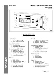
Features Operation Transformer Parallel Control Relay Application
Features Operation Transformer Parallel Control Relay Application
Features Operation Transformer Parallel Control Relay Application

You also want an ePaper? Increase the reach of your titles
YUMPU automatically turns print PDFs into web optimized ePapers that Google loves.
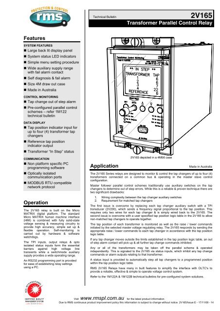
Technical Bulletin2V165<strong>Transformer</strong> <strong>Parallel</strong> <strong>Control</strong> <strong>Relay</strong><strong>Features</strong>SYSTEM FEATURES• Large back lit display panel• System status LED indicators• Simple menu setting procedure• Wide auxiliary supply rangewith fail alarm contact• Self diagnosis & fail alarm• Size 4M draw out case• Made in AustraliaCONTROL MONITORING• Tap change out of step alarm• Pre-configured parallel controlschemes – refer 1M122technical bulletinDATA DISPLAY• Tap position indicator input forup to four (4) transformer tapchangers• Reference tap positionindicator output• <strong>Transformer</strong> “In Step” statusCOMMUNICATION• Non platform specific PCprogramming software• Optically isolatedcommunication ports• MODBUS RTU compatiblenetwork protocol<strong>Operation</strong>The 2V165 relay is built on the MicroMATRIX digital platform. The standardMicro MATRIX human machine interface(HMI) is combined with fully solid-statevoltage sensing & measuring circuitry toprovide high accuracy, simple set up &flexible operation. Self-monitoring iscarried out by hardware & softwarewatchdogs.The TPI inputs, output relays & optoisolated status inputs form the essentialbarriers against high voltage linetransients while a switchmode auxiliarysupply provides a wide operating range.An RS232 programming port is providedfor ease of establishing relay settingsusing a PC.<strong>Application</strong>2V165 depicted in a 4M56 caseMade in AustraliaThe 2V165 Series relays are designed to monitor & control the tap changers of up to four (4)transformers connected on a common bus & operating in the master slave controlconfiguration.Master follower parallel control schemes traditionally use auxiliary switches on the tapchangers to determine out of step errors. While this is a reliable & proven technique there aretwo significant drawbacks:1. Wiring complexity between the tap changer auxiliary switches2. Requirement for matched tap changersThe first issue is overcome by replacing each tap changer auxiliary switch with a TPItransducer (2V200), which sends a frequency signal proportional to the tap position. Thisrequires only two wires for each tap changer & is simply wired back to the 2V165. Thesecond issue is overcome with a user specified tap position logic table in the 2V165 to allownon-matched tap changers to operate together.The tap position of each transformer is monitored as well as the raise / lower commandsinitiated by the selected master voltage regulating relay. The 2V165 responds by sending theappropriate raise / lower commands to each tap changer in accordance with the tap positionlogic table.If any tap changer moves outside the limits established in the tap position logic table, an outof step alarm contact will pick up & all further tap change commands inhibited.Any or all of the transformers may be taken off the parallel scheme & operatedindependently. This is signaled to the 2V165 via status inputs, which inhibit any tap changecommands or alarm outputs relating to that transformer.A status input is provided to automatically step all tap changers to a programmed positionwithin the tap position logic table.RMS 2V165 <strong>Relay</strong>s have many in built features to simplify the interface with OLTC's toprovide a reliable, effective & simple to operate voltage control system.Refer to the 1M122A & 1M122B technical bulletins for pre-configured system solutions.Visit www.rmspl.com.au for the latest product information.Due to RMS continuous product improvement policy this information is subject to change without notice. 2V165/Issue E - 17/11/08 - 14
<strong>Control</strong> FunctionsTPI INPUTSFour (4) TPI inputs are provided to accept a 1 to 5K HZ frequencycoded signals from the RMS manufactured 2V200 TPI transducers.The 2V165 is programmed with the number of taps & direction foreach transformer. A table is established by the user for the correcttap positions relative to a reference position. e.g.Reference Tap 1 Tap 2 Tap 3 Tap 4 Tap 5 … Tap n<strong>Transformer</strong> 1 1 2 3 4 5 … n1<strong>Transformer</strong> 2 1 2 3 4 5 … n2<strong>Transformer</strong> 3 1 1 2 2 3 … n3<strong>Transformer</strong> 4 20 19 18 17 16 … n1Pre-defined tap position logic tableIf the tap of any transformer steps outside the pre-defined band theout of step contact will pick up. A user specified time delay (1-30s in0.5s steps), is provided to allow for differences in tap changeroperate times.It should be noted that this table is only required when tap changersare not matched. The tap position logic table template on this pageshould be completed & supplied with the 2V165 ordering codewhere unmatched tap changers are to be used. The 2V165 will thenbe supplied pre-programmed with the specified configuration.TAP RAISE / LOWER INITIATE INPUTSTwo (2) separate status inputs are provided to detect tap raise &tap lower initiate signals from the master voltage regulating relay.These are used to allow the 2V165 to check that tap positionchanges only occur in synchronization with tap raise / lowercommands. An input control signal of 1s minimum duration isrequired.TAP RAISE / LOWER INITIATE OUTPUTSWhen a tap raise or lower input is detected the 2V165 sendsspecific tap change output commands to each transformer suchthat the positions in the pre-defined tap position logic table areobserved. A continuous contact output is provided which is resetwhen the corresponding tap position indicator changes position.Tap raise must be wired to provide an increase in system volts.Tap lower must be wired to provide a reduction in system volts.OUT OF STEP ALARMWhen a tap raise or lower command is output, an out of stepalarm timer is initiated. If all tap changers have not moved to thespecified tap within the user specified time delay (1-30s in 1ssteps), the alarm contact will close & a message identifying theproblem tap changer displayed.TAP CHANGE FEEDBACK OUTPUT CONTACTThis contact is closed when a tap raise / lower command pulse isreceived from the 2V164 AVR & is reset when all transformershave successfully moved to the next position in the tap positionlogic table. This contact is wired back to the 2V164 tap changefeedback status input to pause the interval timer from startinguntil all transformers have completed the tap change sequence.ALL TRANSFORMERS OFF GROUP OUTPUT CONTACTWhen all transformers are set to OFF GROUP via the ONGROUP status inputs, this N/O contact is closed. This function isuseful to automatically inhibit the local AVR to avoid tap changefail & voltage level alarms.IN GROUP STATUS INPUTSA status input is provided for each transformer to signal if thetransformer is operating as part of the parallel group. This isindicated by an LED on the front panel with the text ON GROUP.Tap raise & lower commands will be inhibited for transformers notON GROUP & its tap position not used to initiate an out of stepalarm.AUTO HOMEWhen a transformer is put back ON GROUP it will automaticallyhome to the Reference Tap Position to match the othertransformers ON GROUP. A user specified time delay (10-300s in5s steps), is provided to allow for the tap changer to reach thespecified target position during which period the Out of Stepalarm is inhibited.GO TO SPECIFIED TAPA status input is provided which may be initiated to drive all ONGROUP transformer tap changes to a user specified referencetap position. An initiate pulse of 1s minimum is required.OPERATIONAL INDICATORSLEDs indicate the following conditions.• <strong>Transformer</strong> 1 ON GROUP• <strong>Transformer</strong> 2 ON GROUP• <strong>Transformer</strong> 3 ON GROUP• <strong>Transformer</strong> 4 ON GROUP• Tap change in progress• Out of step alarm• Healthy• ServiceDATA DISPLAYDuring normal operation the front panel LCD provides the followinginformation:• The tap position of each transformer• <strong>Transformer</strong> out of step statusTPI ANALOGUE OUTPUTA single tap position indicator analogue output signal is providedfor interface to an RTU. The analogue output is linked to thereference tap position (= transformer 1 tap position if matched tapchangers are used).Output:4 to 20mACompliance voltage: 5VMaximum burden: 250 OhmsAccuracy: +/-3%Analogue output:• Tap 14mA• Tap N20mAWhere N = maximum selected tap settingTAP POSITION LOGIC TABLE TEMPLATE – Table 1T1T2T3T4(Only required when tap changers are not matched)Reference Tap Position1 2 3 4 5 6 7 8 9 10 11 12 13 14 15 16 17 18 19 20 21 22 23 24 25 26 27 28 29 30Complete this table with the desired relative transformer tap positions & submit with the ordering code for factory programming.Increased transformer voltage output is to the right. i.e. an increase in the reference tap position will result in an increase in system voltage.Visit www.rmspl.com.au for the latest product information.Due to RMS continuous product improvement policy this information is subject to change without notice. 2V165/Issue E - 17/11/08 - 24
Technical DataRELAY FAIL ALARMA C/O alarm contact is maintained in the energized state when allof the following conditions are met:• The auxiliary supply is applied• The internal 24V DC rail is within acceptable limits• The CPU hardware watchdog maintains a pulsing outputA CPU software watchdog records “suspect” events to an assertregister and if necessary performs a soft restart.OUTPUT CONTACT RATINGSMake & carry30A AC or DC (Limits L/R=40ms & 300V max.) for 0.2s20A AC or DC (Limits L/R=40ms & 300V max.) for 0.5s5A AC or DC continuouslyBreak (Limits 5A & 300V max.)1,250VA AC resistive250VA at 0.4PF AC inductive75W DC resistive30W DC inductive L/R = 40ms50W DC inductive L/R = 10msINSULATION WITHSTANDIEC60255-5 2KV RMS & 1.2/50 5KV impulse between:♦ all input terminals & frame♦ all output terminals & frame♦ all input & output terminals♦ each input group♦ each output groupHIGH FREQUENCY DISTURBANCEIEC60255-22-1 2.5KV 1MHz common mode1.0KV 1MHz differential modeELECTROSTATIC DISCHARGEEN61000-4-2:1995 8KV Level 3RADIO FREQUENCY INTERFERENCEEN61000-4-3:1995 10V/m Level 3FAST TRANSIENT DISTURBANCEEN61000-4-4:1995 4KV Level 4OPERATING TEMPERATURE RANGE-5 to +55 degrees Celsius ambient operating temperature range.ACCESSORIES SUPPLIED WITH EACH SYSTEM1 x M4 self threading mounting screw kit P/N 290-406-1512 x M4 terminal screw kit (28 per kit) P/N 290-407-1531 x Product Test ManualPC TO µMATRIX SERIAL CABLEOne cable supplied with each order.P/N 290-406-151PROGRAMMING PORT SERIAL CABLECOMMUNICATIONSTwo (2) communications ports are available.Programming portThe programming port is accessible from the front panel of therelay via an RS232 physical link & PC configuration programsupplied with the relay. The µMATRIXwin configuration programis designed to operate with all relays from the Micro MATRIXrange & with all installed firmware version.Network portThe network port is intended for applications where permanentconnection to a master control system is required. An opticallyisolated RS232 or RS485 physical layer is provided for thisfunction.The RS485 connection is intended for applications where multipleµMATRIX relays are to be connected on a commoncommunications bus.The RS232 connection is intended for interface to an RS232 tooptic fiber converter in environments subject to extreme electricalinterference.The network port may be used for a permanent link to a modem,remote PC, data concentrator or SCADA system. The standardcommunications protocol is MODBUS RTU.Changing the Network port from RS485 to RS232µMATRIX relays are shipped with the rear network port terminalsconfigured as RS485. This configuration may be changed in thefield to RS232 if required by withdrawing the relay module fromthe case & changing the three configuration links as depicted.Visit www.rmspl.com.au for the latest product information.Due to RMS continuous product improvement policy this information is subject to change without notice. 2V165/Issue E - 17/11/08 - 34
Ordering InformationGenerate the required ordering code as follows: e.g. 2V165 BBBBA2V1651 2 3 4 51 AUXILIARY SUPPLY RANGEA 20-70V DC B 40-300V DC / 40-275V AC2 DIGITAL INPUT OPERATING VOLTAGE – GROUP 1Opto-isolated inputABC24-80V AC/DC75-150V AC/DC150-300V AC/DC3 DIGITAL INPUT OPERATING VOLTAGE – GROUP 2Opto-isolated inputABC24-80V AC/DC75-150V AC/DC150-300V AC/DC4 DIGITAL INPUT OPERATING VOLTAGE – GROUP 3Opto-isolated inputABC24-80V AC/DC75-150V AC/DC150-300V AC/DC5 TPI ANALOGUE OUTPUTSABNot requiredRequired 4 to 20mATAP POSITION LOGIC TABLE FIRMWAREA Not required Matched tap changersB Non matched tap changers Complete the table on page 22V165 wiring diagram - <strong>Relay</strong> shown in de-energised condition 1COMMUNICATIONS(RS 232 SCADA option)D9RS232 PC Programming port<strong>Transformer</strong> 1 IN GROUPStatus input group 1<strong>Transformer</strong> 2 IN GROUPVx35797252723303432Powersupply /CPU failalarmTap raise<strong>Transformer</strong> 1Tap lowerNetworkport242628SENDRECEIVEGROUND<strong>Transformer</strong> 3 IN GROUPStatus input group 2111315364038Tap raise<strong>Transformer</strong> 2Tap lowerCOMMUNICATIONS(RS 485 SCADA option)D9RS232 PC Programming port<strong>Transformer</strong> 4 IN GROUPTap raise input commandStatus input group 3Tap lower input commandGo to specified tap1316221822202242464448525019Tap raise<strong>Transformer</strong> 3Tap lowerTap raise<strong>Transformer</strong> 4Tap lowerNetworkportBIAS linksJ19 J18242628SHIELDRS485 Shielded twistedpair cable (Up to 1Km)120 OhmTo other uMATRIX relays (Up to 32 units)Fit external terminating resistor to end of BUS relay onlyFit internal BIAS jumper links for single relay connection only<strong>Transformer</strong> 1 tap position indicator input<strong>Transformer</strong> 2 tap position indicator input<strong>Transformer</strong> 3 tap position indicator input<strong>Transformer</strong> 4 tap position indicator input35373941434547492117108141253552Out of stepalarmTap ChangefeedbackAll OFF LINETap positionoutputVisit www.rmspl.com.au for the latest product information.Due to RMS continuous product improvement policy this information is subject to change without notice. 2V165/Issue E - 17/11/08 - 44
Australian ContentUnless otherwise stated the product(s) quotedare manufactured by RMS at our productionfacility in Melbourne Australia. Approximately60% of our sales volume is derived fromequipment manufactured in house with a localcontent close to 90%. Imported componentssuch as semi-conductors are sourced from localsuppliers & preference is given for reasonablestock holding to support our build requirements.Quality AssuranceRMS holds NCSI (NATA Certification ServicesInternational), registration number 6869 for thecertification of a quality assurance system toAS/NZS ISO9001-2000. Quality plans for allproducts involve 100% inspection and testingcarried out before despatch. Further details onspecific test plans, quality policy & proceduresmay be found in section A4 of the RMS productcatalogue.Product PackagingProtection relays are supplied in secureindividual packing cardboard boxes with mouldedstyrene inserts suitable for recycling. Eachproduct & packing box is labeled with the productpart number, customer name & order details.Design ReferencesThe products & components produced by RMSare based on many years of field experiencesince <strong>Relay</strong>s Pty Ltd was formed in 1955. A largepopulation of equipment is in service throughoutAustralia, New Zealand, South Africa & SouthEast Asia attesting to this fact. Specific product &customer reference sites may be provided onapplication.Product WarrantyAll utility grade protection & auxiliary relayproducts, unless otherwise stated, are warrantedfor a period of 24 months from shipment formaterials & labour on a return to factory basis.Repair of products damaged through poorapplication or circumstances outside the productratings will be carried out at the customer’sexpense.Standard Conditions of SaleUnless otherwise agreed RMS Standard Terms &Conditions (QF 907) shall apply to all sales.These are available on request or from our website.<strong>Relay</strong> Monitoring Systems Pty Ltd6 Anzed Court, Mulgrave, Victoria 3170, AUSTRALIA© 2008 <strong>Relay</strong> Monitoring Systems Pty LtdDue to RMS continuous product improvement policy this information is subject to change without notice.