
Create successful ePaper yourself
Turn your PDF publications into a flip-book with our unique Google optimized e-Paper software.
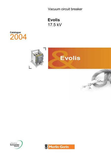
Vacuum circuit breaker<strong>Evolis</strong><strong>17.5</strong> <strong>kV</strong>Catalogue2004
Presentation Enlarged products offer 0PE55102Busbar connectioncoverTerminal blockconnectorMulti 9 circuit breakerSepam series 20-40LampPush buttonVoltage presenceindicatorCurrenttransformerDoor handleEarthing switchoperating mechanismExtraction tableSurgearresterEarthingswitchHeatingresistance3
Presentation <strong>Evolis</strong>: versatility 0Where to use <strong>Evolis</strong>?PE551012 versions adapt to your fixed or withdrawableinstallation:b Full versionwithdrawable with cradleb Fixed versionbasic circuit breaker with kits deliveredin separate4
0<strong>Evolis</strong> circuit breakers are used to protect and control public or industrial mediumvoltage electrical distribution networks.<strong>Evolis</strong> is indoor switchgear that is particularly suited to the production and renovationof HV/MV, MV/MV and MV/LV substations.It is suitable for the protection of all types of applications:cables, lines, motors, capacitors, transformers, bus sectioning of sources, etc.2004602004615
1250 A630 APresentation <strong>Evolis</strong>: performance 0What does <strong>Evolis</strong> offer you?<strong>Electric</strong>al characteristicsPE55098b 3 rated voltages:v 7.2 <strong>kV</strong> index 7,v 12 <strong>kV</strong> index 12,v <strong>17.5</strong> <strong>kV</strong> index 17.b 3 breaking capacities:v 25 kA index P1,v 31.5 kA index P2,v 40 kA index P3.b 3 rated currents:v 630, 1250, 2500.Full version200493P3: 40 kARated breaking currentP1: 25 kAP2: 31.5 kA2500 A1250 A630 A2500 A1250 A630 A2500 A1250 A630 ARated current2500 A1250 A630 ARated voltage7.2 <strong>kV</strong>12 <strong>kV</strong><strong>17.5</strong> <strong>kV</strong>2500 A1250 A630 A2500 A1250 A630 A2500 A1250 A630 A2500 A1250 A630 A2500 A1250 A630 AFixed versionDE55180P3: 40 kARated breaking currentP1: 25 kAP2: 31.5 kA2500 A1250 A630 A2500 A2500 A1250 A630 ARated current2500 A1250 A630 ARated voltage7.2 <strong>kV</strong>12 <strong>kV</strong><strong>17.5</strong> <strong>kV</strong>2500 A1250 A630 A2500 A1250 A630 A2500 A1250 A630 A2500 A1250 A630 A2500 A1250 A630 A6
Presentation <strong>Evolis</strong>: heavy duty and innovative 0200205How does <strong>Evolis</strong> eliminate faults?<strong>Electric</strong>al enduranceA magnetic field is applied along the axis of the vacuum interrupter contacts.This process maintains the arc in a diffuse mode even at high current values.It ensures optimum distribution of the energy over the contact surface thus avoidinglocalised hot spots.b The advantages of this technique:v a very compact vacuum interrupter,v low dissipation of arcing energy in the vacuum interrupter.<strong>Evolis</strong> is in conformity with highest electrical endurance class(IEC 62271-100: class E2).200110Mechanical enduranceb This magnetic field is generated by a patented external coil which surrounds thecontact zone. This solution provides many advantages:v a simplified and therefore reliable vacuum interrupter,v heavy duty contacts which do not distort during repeated switching operations,v considerable reduction in control mechanism energy.b For the first time, a low voltage device control mechanism has been integrated ina medium voltage circuit breaker. The Masterpact control mechanism used on <strong>Evolis</strong>provides the benefits of a system that has proven itself for over 10 years on hundredsof thousands of installations.<strong>Evolis</strong> is in conformity with most demanding mechanical endurance class(IEC 62271-100: class M2).PE55107Protection chainThe Sepam series 20-40 protection unit combined with current sensors, provides acomprehensive measurement, protection and energy management chain.b A high performance and economical solutionSepam series 20-40, due to its modular nature, provides a cost-effective solutionadapted to every requirement.b Easy to order and installv all components in the protection chain are referenced and deliverable very rapidly,v the functioning of the protection chain integrated in the <strong>Evolis</strong> circuit breaker hasbeen fully tested and certified.b The power of a multifunctional digital unitSepam series 20-40 is not simply a protection relay, it is a multi-functional unitnotably providing:v circuit breaker diagnosis functions (number of switching operations, operatingtime, charging time, cumulative breaking current),v direct circuit breaker control whatever type of release,v remote operation of the equipment through the Modbus communication option.The Sepam series 20-40 is in compliance with the LPTC (Low Power CurrentTransducers) as defined by standard IEC 60044-8 (draft version).7
Presentation<strong>Evolis</strong>:tailored to your requirements 0What does <strong>Evolis</strong> offer you?Circuit breakers that combine simplicityof selection and richness of offer.2 versions are proposed:b full version comprising thewithdrawable circuit breaker and itscradleb fixed version and separatelydelivered kits.“Universal” accessories can be addedto either version.E.g:release, contact, motor, connection,inter-locking systems, etc...PE55101Full version:a fully assembled and tested unitb As standard, the circuit breaker is equiped with all the components required for“ready to use” withdrawable installation in metalclad cubicles.This unit is easy to integrate in a cubicle environment, all it needs is mechanicalfixing in place. An installation guide explains the required operations in detail.b This version provides the guarantees of a highly reliable unit, whose componentsfunction in perfect harmony. Critical points such as inter-locking systems, dielectricwithstand and temperature rise have been checked thoroughly during design.It is a system that is fully integrated and tested by the manufacturer, in conformitywith IEC standards 60298 and 62271-100.The interface with optional earthing switch is already existing on the floorof the cradle.8
0Fixed version andhigh added value accessories:b The circuit breaker is proposed in its most simple configuration. In this case itcan be combined with additional functions, to satisfy various requirements.PE40002b This version offers maximum flexibility to adapt to constraints in existing cubiclesor to operating specifications:v retrofit: fixed and withdrawable installation,v block-type cubicle or metal enclosed substation: fixed or removable installation,v compartmented cubicle: fixed and withdrawable installation.b The panel builder chooses the components he needs for a “customised” solutiontailor made to his know-how.Build your own version...DE30115DE30113PE40002DE301149
Presentation<strong>Evolis</strong>: the commitmentof a major manufacturer 0200477What guarantees does <strong>Evolis</strong> provide?Conformity with standardsb Conformity with standards is a guarantee of suitability for the required function,the very basis of the contract between the supplier and the customer:v dependability,v operator safety.It allows specifications to be fully satisfied whilst complying with local contraints.During its design phase, <strong>Evolis</strong> was subjected to a serie of tests which confirmedexcellent performance levels, beyond the standards requirements.b Type testing:v dielectric tests,v temperature rise,v breaking capacity,v thermal withstand,v mechanical endurance,v electrical endurance.b Specific testing:v ageing,v transport and storage.N.B.:IEC 60694: common specifications for high voltage switchgear and controlgear standardsIEC 62271-100: high voltage alternating current circuit breakersIEC 60298: A.C metal-enclosed switchgear between 1 <strong>kV</strong> and 52 <strong>kV</strong>.Comment: for more information, consult the IEC organisation site: www.iec.ch.Certificationb Certification of conformity provides guarantees that the product:v has been subjected to type testing according to the procedures of standardEN 45001 in accredited laboratories by independent organisations,v is in conformity with recognized international standards.b <strong>Evolis</strong> is under process of certification by external EN 45011 accreditedorganisations.N.B.:EN 45001: general requirements for the competence of testing and calibration laboratoriesEN 45011: general requirements for bodies operating product certification systems.10
0200465Guaranteed quality<strong>Schneider</strong> <strong>Electric</strong> integrates a functional organisation in each of its units with themain mission of checking quality and overseeing compliance with standards.The quality system, for the design and manufacture of <strong>Evolis</strong> circuit breakers,is certified to be in conformity with the requirements of ISO 9001 and ISO 9002quality assurance standards.b ISO 9001: quality system for design/production and installationb ISO 9002: quality system for production and installationb IQNET: international certification network.PE55105Systematic controlDuring manufacture, each circuit breaker is subjected to routine systematic testing,with the aim of checking both quality and conformity.b Control of vacuum interruptersEach vacuum interrupter, sealed and airtight, is checked for the quality of thevacuum obtained. This pressure measurement is based on the proven “magnetrondischarge” method.Using this sophisticated procedure, measurement is very precise and does notrequire access to the inside of the bulb, thus not affecting the airtight seal.b Control of the circuit breakerA rigorous set of tests and measurements is carried out on each circuit breaker.The results obtained are reported on and signed off by the quality control departmenton the test certificate for each device, thereby guaranteeing product traceability.PE55104PE55103Respecting the environmentb <strong>Schneider</strong> <strong>Electric</strong> has given the goal of:v actively participating in environmental protection, from a circuit breaker's designright through to its end of life,v complying with the environmental requirements of both its customers and endusers of its products.b For <strong>Evolis</strong> circuit breakersv development teams integrated the product’s end-of-life right from the design stage.The product is easy to dismantle, all the materials used are recyclable and nonpolluting,v plastic parts are marked to identify the material,v the circuit breakers are produced in factories which respect the environment.Our subsidiary at Aubenas, France has been awarded the ISO 14001 standardcertification (environmental management system).Comment: for more information, consult the ISO organisation site: www.ISO.CH11
Presentation <strong>Evolis</strong>: simple to use and install 0061032NHow <strong>Evolis</strong> makes your life easier?Choice<strong>Evolis</strong> circuit breakers offer a comprehensive and rational range:b 3 operating voltages (7.2 <strong>kV</strong> - 12 <strong>kV</strong> - <strong>17.5</strong> <strong>kV</strong>)b 3 breaking capacities (25 kA - 31.5 kA - 40 kA)b 3 current ratings (630 - 1250 - 2500 A)b 1 common range of accessories and auxiliariesb 2 versions: full and fixed with accessories.Ordering and deliveryb You can order:v the cradle before the circuit breaker,v accessories, at the last moment, that you will easily be able to install yourself.b Thanks to modular design and local customising, the delivery is faster.Installation<strong>Evolis</strong> is easy to incorporate in cubicles.b Optimisation of volumes: one single height and depth throughout the range.b <strong>Electric</strong>al auxiliaries are interchangeable throughout the range.b Adjustable device height in the cubicle.b Variable phase to phase connection points.PE40002OperationIncreased safety<strong>Evolis</strong> has been designed and industrialised to provide maximum safetyfor operators whilst guaranteeing the simplicity and rapidity of operations.b Protective metal shutters.b Safety interlocking systems to avoid operator errors when racking in or out.b Racking in/out possible only with the door closed.b Safety interlockings to avoid operators errors on earthing switch.Reduced maintenanceb Common stock of replacement parts with the Masterpact circuit breaker.b Diagnosis of the circuit breaker's functional chain using Sepam series 20-40.<strong>Evolis</strong> circuit breaker12
0200467EFrom pre-engineering to switchboardmanufacturing, a “toolkit” exists forpanel builders to highlight theirknow-how and optimise their workaround <strong>Evolis</strong>.Tools to complement your know-howDesign guideThis document provides you with all the technical recommendations you requirefor your calculations when designing cubicles and incorporating equipment inconformity with IEC standard 60 298.E.g.:b defining the switchgear,b dielectric strength,b busbar calculation,b temperature rise calculation,b definition of IP protection index.200475Installation guideThis document provides you with all the information and recommendations you needto incorporate the circuit breaker and its accessories in a cubicle.E.g.:b dimensions and space requirements,b mechanical interface,b power circuit connection,b auxiliary connection,b layout diagrams.200469CAD libraryFor easier and more reliable integration of <strong>Evolis</strong> in a cubicle environment,an extensive library of dimensional drawings and electrical layout diagramsis available in AUTOCAD and ACROBAT READER formats (DWG/DXF/PDF).PE55108Internet siteMissing a certificate? Lost a technical manual?Connect up to our web site where you can download all of our technicaldocumentation (http://www.mvproduct.merlin-gerin.com).Become a club member and discover the information for designing and choosingthe right product and integrating it into your switchboard.13
Circuit breaker Contents 0This chapter provides useful informationin selecting the performance levels ofyour <strong>Evolis</strong> circuit breaker.It also describes all the functionsassociated with each version.Panorama 16Optional LV accessories 16Description of withdrawable full version 17Full version 18Performance tables 18Power circuit 20Racking in 21Low voltage plug and socket 22Fixed version and separated accessories 24Performance tables 24Connecting the power circuit 26Power circuit 27Racking in and support frame 28Low voltage accessories 29Opening circuit 29Remote control 31Indication 33Low voltage plug, socket and terminal blocks 34Locking/Interlocking 35Dimensions 36Full version 36Fixed version 3715
Panorama Optional LV accessories 0PE55109Circuit breaker“open position”padlockingLow voltageplugCircuit breaker“open position”key lockingPush buttondisablingBloc of 4 O/Cposition contactsShunt closing releaseShunt opening releaseor undervoltage release“Ready to close”contactLow energy releaseOperationcounterMotor mechanism16
PanoramaDescription of withdrawablefull version 0PE55110MV connectorsShuttersBushingsFingersClustersArmsRacking baseCircuit breakerA1 contact forcircuit breaker in“cranked” position.BBloc of 4 contactsfor circuit breaker“racked in/out” positions.Please note:using A and B you can signal“C.B. OK to be operated”: PAF,and “C.B. in test position”.Racking truck17
Full version Performance tables 07P1 630 to 17P3 2500Common characteristics according to IEC 62271-100rated frequency fr (Hz) 50 & 60short-time withstand current Ik for tk = 3 s (kA) rms Ik = Iscrated peak withstand current Ip peak (kA) Ip = 2.5 & 2.6 Ikrated short circuit making current peak (kA) = 2.5 & 2.6 Iscoperating sequenceO - 3 mn - CO - 3 mn - COO - 0.3 s - CO - 3 mn - COO - 0.3 s - CO - 15 s - COoperating times opening ms < 50breaking ms < 60closing ms < 65mechanical endurance class M2number of operations 10000electrical endurance class E2number of operations 25 kA 10031.5 kA 5040 kA 30capacitive current breakingclass C1<strong>Electric</strong>al characteristics according to IEC 62271-100circuit breaker 7P1 7P1 7P1 7P2 7P2 7P2 7P3 7P3 7P3 12P1630 1250 2500 630 1250 2500 630 1250 2500 630rated voltage Ur (<strong>kV</strong>) rms 7.2 7.2 7.2 7.2 7.2 7.2 7.2 7.2 7.2 12rated insulation voltage Ud (<strong>kV</strong>) rms 20 20 20 20 20 20 20 20 20 28rated insulation voltage Up (<strong>kV</strong>) peak 60 60 60 60 60 60 60 60 60 75rated short-circuit breaking current Isc (kA) rms 25 25 25 31.5 31.5 31.5 40 40 40 25rated normal current (-25° +40°C) Ir (A) rms 630 1250 2500 630 1250 2500 630 1250 2500 630climatic version -25° +40°C b b b b b b b b b bInstallation and connectionsphase distance:between poles (mm) 145 & 185 145 & 185 240 185 185 240 240 240 240 145 & 185dimensions C.B. and cradle (mm) width (W) 592 & 702 592 & 702 882 702 702 882 882 882 882 592 & 702depth (D) 1140 1140 1140 1140 1140 1140 1140 1140 1140 1140height (H) 965 965 965 965 965 965 965 965 965 965mass C.B. and cradle (kg) 165 & 174 165 & 174 272 174 174 272 272 272 272 165 & 17418
Full version020020620020720020812P1 12P1 12P2 12P2 12P2 12P3 12P3 12P3 17P1 17P1 17P1 17P2 17P2 17P2 17P3 17P3 17P31250 2500 630 1250 2500 630 1250 2500 630 1250 2500 630 1250 2500 630 1250 250012 12 12 12 12 12 12 12 <strong>17.5</strong> <strong>17.5</strong> <strong>17.5</strong> <strong>17.5</strong> <strong>17.5</strong> <strong>17.5</strong> <strong>17.5</strong> <strong>17.5</strong> <strong>17.5</strong>28 28 28 28 28 28 28 28 38 38 38 38 38 38 38 38 3875 75 75 75 75 75 75 75 95 95 95 95 95 95 95 95 9525 25 31.5 31.5 31.5 40 40 40 25 25 25 31.5 31.5 31.5 40 40 401250 2500 630 1250 2500 630 1250 2500 630 1250 2500 630 1250 2500 630 1250 2500b b b b b b b b b b b b b b b b b145 & 185 240 185 185 240 240 240 240 185 185 240 185 185 240 240 240 240592 & 702 882 702 702 882 882 882 882 702 702 882 702 702 882 882 882 8821140 1140 1140 1140 1140 1140 1140 1140 1140 1140 1140 1140 1140 1140 1140 1140 1140965 965 965 965 965 965 965 965 965 965 965 965 965 965 965 965 965165 & 174 272 174 174 272 272 272 272 174 174 272 174 174 272 272 272 27219
Full version Power circuit 0DE30118Compositionb The power circuit comprises:v mobile contacts made up of disconnecting clusters and arms mounted on thecircuit breaker,v fixed fingers located on the cradle and insulated by bushings and metal shutters.b This unit gives perfect control of dielectric, short time withstand current andtemperature rise considerations.All of these characteristics have been validated by testing.Power circuit200159Connectionb Customer connection is easily achieved outside the cradle:v on vertical copper terminals integrated in the bushing,v through a set of connectors, also used on the basic circuit breaker unit.Connection variants described on page 26 are possible.Comments:The dielectric withstand values shown in the performance tables are guaranteed excluding theseconnectors.The panel builder should check the overall cubicle connection configuration.3 sets of connectors201252b For Ur = <strong>17.5</strong> <strong>kV</strong> CBs with 185 mm phase-to-phase distance, the field deflectorsare used to increase the dielectric withstand from 75 <strong>kV</strong> to 95 <strong>kV</strong>.Field deflectors20
Full version Racking in 0DE30119CompositionThe “racking in” function is provided by:b The racking truck supporting the circuit breaker (mobile part).b The cradle including the bushings (fixed part).b The LV plug.Operating procedureb The circuit breaker moves through 3 stable states:v service: circuit breaker racked in and locked in place; low voltage plug connected,v test: circuit breaker racked out and locked in place; low voltage plug connected,v extracted: the circuit breaker can be unlocked and extracted from the cubicle.3 stable states for manual operationDE55189DE30124DE30125DE30126Service position Test position Extracted positionPropulsive systemComments:Arrows indicate the “lock-in-positions” for the circuit breaker and the low voltage connector.FunctionsDE30121DE30122ShuttersLocked C.B.positioncontactRacked in/racked outcontactsMT66049Earthing deviceb A propulsive system combined with a screw-shaft makes racking in and rackingout easier. The racking mechanism can be operated with the door closed.Interlocking prevents the user from inserting the lever until the racking base selectorhas been positioned to the racking in/racking out position.b Interlocking between circuit breaker position and cradle makes operation safer:racking in or out only when the circuit breaker is open.b Interlocking is also provided between the low voltage connector and the circuitbreaker. Racking in is only possible when the low voltage connector is connected.The floor of the cradle includes all necessary fixing holes to position properly theoperating mechanism and the power circuit of the earthing switch. This allowsreliable operations of the earthing switch and guarantees the interlocking betweencircuit breaker and earthing switch.b Earthing is automatically achieved throughout the whole racking in operation.b Protective shutters placed on the cradle prevent access to the racking fingerswhen the device is extracted (protection index: IP2X).b For maintenance operations, it is possible to:v padlock the shutters in the closed position,v unlock the shutters mechanism to access the racking fingers.b A full proof protection enables cradle and circuit breaker to be matched up.This system is mounted on the racking base.Part of it has to be assembled by the panel builder on the cubicle floor.DE30136Accessoriesb A set of auxiliary contacts:v 4 racked in/racked out circuit breaker position contacts,v 1 contact indicating that the circuit breaker is locked in place in the cradle.b The earthing for the base is provided by a copper brush.b A key locking system (Ronis or Profalux) for the racked out positionon the circuit breaker will provide increased safety when working downstreamof the circuit breaker. This system is combined with an earthing switch(refer to page 43).b Circuit breaker compartment door interlocking.b The device allows circuit breaker operation only when the door is closedfor full version with truck.Cubicle door interlocking mechanism21
Full version Low voltage plug and socket 0Main functionsThis plug and socket system provides an auxiliary supply connection with a high levelof electrical safety.Interlocking functionIt is possible to connect and disconnect the plug only if the breaker is in racked outposition. It is not possible during the racking in operation.Two versions of plug and socketDE30127DE30128Plug and socket 18 pin versionAn 18 pin versionThis version allows you to connect:b For remote controlv 1 electric motor,v 1 shunt closing release,v 1 shunt opening release,v 1 contact “ready to close”.b For auxiliary contactsv 2 changeover contacts,v 1 normally-open contact,v 1 normally-closed contact.A 42 pin versionThis version allows you to connect:b For remote controlv 1 electric motor,v 1 shunt closing release,v 2 shunt opening releasesor 1 shunt opening release + 1 undervoltage release,v 1 contact “ready to close”,v 1 low energy release,v 1 fault-trip indication contact,v 1 SDE contact remote reset.b For auxiliary contactsv 2 changeover contacts,v 5 normally-open contacts,v 4 normally-closed contacts.Plug and socket 42 pin version22
230
Fixed version Performance tables 07P1 630 to 17P3 2500Common characteristics according to IEC 62271-100rated frequency fr (Hz) 50 & 60short-time withstand current Ik for tk = 3 s (kA) rms Ik = Iscrated peak withstand current Ip peak (kA) Ip = 2.5 & 2.6 Ikrated short circuit making current peak (kA) = 2.5 & 2.6 Iscoperating sequenceO - 3 mn - CO - 3 mn - COO - 0.3 s - CO - 3 mn - COO - 0.3 s - CO - 15 s - COoperating times opening ms < 50breaking ms < 60closing ms < 65mechanical endurance class M2number of operations 10000electrical endurance class E2number of operations 25 kA 10031.5 kA 5040 kA 30capacitive current breakingclass C1<strong>Electric</strong>al characteristics according to IEC 62271-100circuit breaker 7P1 7P1 7P1 7P2 7P2 7P2 7P3 7P3 7P3 12P1 12P1 12P1630 1250 2500 630 1250 2500 630 1250 2500 630 1250 2500rated voltage Ur (<strong>kV</strong>) rms 7.2 7.2 7.2 7.2 7.2 7.2 7.2 7.2 7.2 12 12 12rated insulation voltage Ud (<strong>kV</strong>) rms 20 20 20 20 20 20 20 20 20 28 28 28rated insulation voltage Up (<strong>kV</strong>) peak 60 60 60 60 60 60 60 60 60 75 75 75rated short-circuit breaking current Isc (kA) rms 25 25 25 31.5 31.5 31.5 40 40 40 25 25 25rated normal current (-25° +40°C) Ir (A) rms 630 1250 2500 630 1250 2500 630 1250 2500 630 1250 2500climatic version -25° +40°C b b b b b b b b b b b bInstallation and connectionsphase distance between poles:without MV connections (mm) 145 & 185 145 & 185 240 185 185 240 240 240 240 145 & 185 145 & 185 240dimensions C.B. (mm) width (W) 470 470 & 550 660 550 550 660 660 660 660 470 & 550 470 & 550 660depth (D) 429 429 429 429 429 429 429 429 429 429 429 429height (H) 535 535 535 535 535 535 535 535 535 535 535 535mass C.B. (kg) 51 / 55 51 / 55 79 55 55 79 79 79 79 51 / 55 51 / 55 7924
Fixed version020020920021020021112P2 12P2 12P2 12P3 12P3 12P3 17P1 17P1 17P1 17P2 17P2 17P2 17P3 17P3 17P3630 1250 2500 630 1250 2500 630 1250 2500 630 1250 2500 630 1250 250012 12 12 12 12 12 <strong>17.5</strong> <strong>17.5</strong> <strong>17.5</strong> <strong>17.5</strong> <strong>17.5</strong> <strong>17.5</strong> <strong>17.5</strong> <strong>17.5</strong> <strong>17.5</strong>28 28 28 28 28 28 38 38 38 38 38 38 38 38 3875 75 75 75 75 75 95 95 95 95 95 95 95 95 9531.5 31.5 31.5 40 40 40 25 25 25 31.5 31.5 31.5 40 40 40630 1250 2500 630 1250 2500 630 1250 2500 630 1250 2500 630 1250 2500b b b b b b b b b b b b b b b185 185 240 240 240 240 185 185 240 185 185 240 240 240 240550 550 660 660 660 660 550 550 660 550 550 660 660 660 660429 429 429 429 429 429 429 429 429 429 429 429 429 429 429535 535 535 535 535 535 535 535 535 535 535 535 535 535 53555 55 79 79 79 79 55 55 79 55 55 79 79 79 7925
Fixed versionand separatedaccessoriesConnecting the power circuit 0DE30129Compositionb The basic circuit breaker unit is equipped with drilled copper connection terminals,located at the top and bottom of the breaking poles.b Connectors are mounted on these terminals using the associated bolt work.They enable several connection variants.The same connectors can be also mounted on the bushing connection terminals(see page 20).Fixed connectorshorizontal connectors (H) vertical connectors (V) mixed connectorsA horizontal connector becomes a vertical connector by a 90° rotation.TerminalVariable distance connectorshorizontal spreading vertical spreadingconnectors (H)connectors (V)DE30130P000024DP000023DP000020DP000021DP000022DThe spreading connector enables the connecting distance to be increased by0 to 25 mm.Combined solutionExample3 sets of connectorsP000025DComments:The dielectric withstand values shown in the performance tables do not take into accountthese connectors.These connectors may be fitted with either bare copper, tin plated copper or tin plated aluminiumconductors without any particular protection.The dimensions and shapes of these conductors should be determined by the panel builderaccording to the required dielectric and temperature rise characteristics of the full connectionsystem; typical examples are given in the installation guide.26
Fixed versionand separatedaccessoriesPower circuit 0DE30131CompositionThe panel builder produces the power circuit himself. He has the possibility ofintegrating one of these two highly technical units.b Clusters and fingers.b Arms, clusters, fingers inside bushings.Cluster and fingerb The tulip type cluster has a shape which provides maximum contact surface whilstoptimising heat dissipation. Moreover, in the case of short-circuit, it offers goodcompensation characteristics for electrodynamic forces.Cluster and fingerb The finger is a component designed specifically for the cluster, regarding itsshape, tolerances and materials. Contact between the finger and the cluster isguaranteed by type testing: 1000 racking in-out operations.DE30132Arm, cluster, finger and bushingb The choice of a cylindrical shape for the arm optimises the dielectric withstand andeliminates the need for additional insulation.b The cylindrical shape of the bushing provides excellent dielectric withstand.b It includes a connection terminal that can be fitted with the connectors describedon page 20.Arm, cluster, finger and bushingComment:Performances of the overall unit shall be controlled by the panel builder and are limited to 12 <strong>kV</strong>.Conditions of installation for both units described above are given in the installation guide.For withdrawable circuit breaker <strong>17.5</strong> <strong>kV</strong>, 185 mm phase-to-phase distance, field deflectorsmust be added on bushings.DE30133Field deflectorb For Ur = <strong>17.5</strong> <strong>kV</strong> CBs with 185 mm phase-to-phase distance, the field deflectorsare used to increase the dielectric withstand from 75 <strong>kV</strong> to 95 <strong>kV</strong>.Arm, cluster, finger, bushing, busbar and field deflectors27
Fixed versionand separatedaccessoriesRacking in and support frame 0External tripping deviceThis circuit breaker opening kit allows the panel builders to install a mechanicaltripping by any external action.Example:b To trip the circuit breaker before extracting it from the MV compartment.b To maintain the circuit breaker in open position during racked in and racked outoperations.Note:b This option is included if using of a standard screw shaft racking truck.b See installation guide for design and assembling.Support frameThe support frame allows:b A fixing support to be produced for the circuit breaker. Fixing to the groundis achieved using a roller kit. A drawing enables the interface to be producedbetween the rolling channel and the circuit breaker.b The rolling function is provided using the integrated rollers.Note: please consult the installation guide.200158DE30134DE55182Support frame28
Low voltage accessories Opening circuit 0200202CompositionThe basic circuit breaker equipment includes a shunt trip release unit (MX).b It may also include the following options:v a second MX release,v or an undervoltage release (MN),v or an undervoltage release with time delay (MN + time delay unit),v and a low energy release (MITOP).Opening mechanism circuit diagram200476ENopeningorderopeningorderdelayedopening orderCircuit breaker equipped with an opening releasetime delay unitMXMNMN200213Shunt opening release (MX)This enables the instant opening of the circuit breaker when energised.The permanent energising of the MX locks the circuit breaker in the “open” position.MX shunt opening releaseCharacteristicssupply V AC 50/60 Hz 24 48 100-130 200-250V DC 24-30 48-60 100-130 200-250threshold0.7 to 1.1 Unconsumption (VA or W) pick-up: 200 hold: 4.529
Low voltage accessories Opening circuit 0200213MN undervoltage releaseUndervoltage release (MN)An undervoltage release operates to open the circuit breaker when the voltage at theterminals of the release decreases below 35% of its rated voltage, even in case ofslow and gradual decrease.It doesn’t operate the circuit breaker when the voltage at its terminals exceeds 70%of its rated apply voltage.The closing of the circuit breaker is possible when the values of the voltage at theterminals of the release are equal to, or higher than 85% of its rated voltage.Its closing is impossible when the voltage of the terminals is lower than 35%of its rated supply voltage.Characteristicssupply V AC 50/60 Hz 24 48 100-130 200-250V DC 24-30 48-60 100-130 200-250threshold opening 0.35 to 0.7 Unclosing 0.85 Unconsumption (VA or W) pick-up: 200 hold: 4.5200214Time delay unit for MNTime delay unit for MNTo eliminate spurious tripping of the circuit breaker during momentary voltage dropsMN's action is time-delayed. This function is achieved by adding an external timedelay to the MN release circuit (delay is ajustable).This unit is placed outside of the circuit breaker and can be inhibited by anemergency stop button to obtain instant opening.Characteristicssupply V AC 50/60 Hz 48-60 100-130 200-250V DC 48-60 100-130 200-250threshold opening 0.35 to 0.7 Unclosing 0.85 Unconsumption (VA or W) pick-up: 200 hold: 4.5time delay0.5 s - 0.9 s - 1.5 s - 3 s200268Low energy release (MITOP)This specific coil actuates the opening mechanism of the poles to trip the circuitbreaker. It is characterized by a low energy consumption.Characteristicssupplythresholdresponse time of the circuit breaker at Undirect current0.6 A < I < 3 A11 msAny tripping caused by the Mitop release is indicated momentarily by an SDE typechangeover contact. This Release Unit also includes a coil enabling the remoterearming of the SDE contact.Comment:To use the MITOP release requires the adjustment of a time delay to be set by the protection relayin order to ensure a circuit breaker operating time of 45-50 ms.MITOP low energy release30
Low voltage accessories Remote control 0200203Functionb The remote control enables remote opening and closing of the circuit breaker.b In the case of continuous opening and closing orders, the remote control unitblocks the device in the open position as standard: the anti-pumping function.This function gives absolute priority to the opening order, but and it also stops closingorder and thus avoids the device being locked in an indefinite opening-closing cycle:v the opening and closing coils may be fed power on a constant basis to achieve anelectrical type locking: there is no self-breaking contact inside the device,v the interlocking between the opening and closing orders, whatever their causes,is achieved as standard within the device's control mechanism.Remote control circuit diagramCircuit breaker equipped with remote control200485ENchargedspringsopeningorderclosingorderreadyto closeopenclosedMCHPFOFOFOFCHMXXFCompositionb The remote control comprises:v electrical motor and associated mechanism (MCH) equippedwith a “spring-loaded” limit switch (CH),v two shunt trip releases:- a closing release (XF),- an opening release (MX).b It can be added with:v a “ready to close” contact PF,v a second block of 4 contacts for indication of the O/C position of the device.31
Low voltage accessories Remote control 0200215<strong>Electric</strong> motor (MCH)The MCH unit arms and rearms the energy storage springs as soon as the circuitbreaker is closed. This enables instant reclosing of the device after opening.The arming lever is only used as back up control in the absence of an auxiliaryvoltage.The MCH is equipped as standard with a CH limit switch. This contact indicates the“armed” position of the mechanism (spring charged).Characteristicssupply V AC 50/60 Hz 48-60 100-130 200-240V DC 24-30 48-60 100-125 200-250threshold0.85 to 1.1 Unconsumption (VA or W) 180motor overcurrent2 to 3 In during 0.1 scharging time6 s. max.switching rate3 cycles per minute max.CH contact10 A at 240 VShunt release (XF and MX)200213Closing release (XF)This enables the remote closing of the circuit breaker when the control mechanismis charged.Opening release (MX)This enables the opening of the circuit breaker when energised.Shunt release XF/MXCharacteristics XF/MXsupply V AC 50/60 Hz 24 48 100-130 200-250V DC 24-30 48-60 100-130 200-250consumption (VA or W) pick-up: 200hold: 4.5threshold XF 0.85 to 1.1 UnMX0.7 to 1.1 Un32
Low voltage accessories Indication 0200217200218200216Rotary type O/C position contactsReady to close contactsOperation counter“Open/closed” position contacts (OF)These contacts indicate the “open” or “closed” position of the circuit breaker.b Rotary type change over contacts directly driven by the circuit breakermechanism.b The indicator contacts are proposed:v in standard use for a relaying application,v in low level use for control of plc’s or electronic circuits.This version is compatible with the Sepam series 20-40 unit.Characteristicsdelivered as standard 4maximum quantity 8breaking capacity (A) standard min. load: 100 mA/24 Vcos ϕ: 0.3 V AC 240-380 10/6*AC12/DC12 480 10/6*690 6V DC 24-48 10/6*125 10/6*250 3low levelmin. load: 2 mA/15V DCV AC 24-48 6240 6380 3V DC 24-48 6125 6250 3* standard contacts: 10 A; optional contacts: 6 A (temperature derating)“Ready to close” contact (PF)b The “ready to close” position of the circuit breaker is indicated by a mechanicalindicator and a changeover contact PF.b This information simultaneously indicates that:v the circuit breaker is open,v the stored energy springs are charged,v there is no permanent closing order,v there is no permanent opening order which could be caused by:- safety opening order (2nd MX or MN)- device locked in the open position with a key lock.Characteristicsdelivered as standard 0maximum quantity 1breaking capacity (A) standard min. load: 100 mA/24 Vcos ϕ: 0.3 V AC 240-380 5AC12/DC12 480 5690 3V DC 24-48 3125 0.3250 0.15low-levelmin. load: 2 mA/15V DCV AC 24-48 3240 3380 3V DC 24-48 3125 0.3250 0.15Operation counter (CDM)The operation counter is visible on the front face.It displays the number of operating cycles that the device performs.33
Low voltage accessoriesLow voltage plug, socket andterminal blocksThe fixed circuit breaker is delivered with the mounted low voltage plug & socketor with the low voltage terminal blocks.The withdrawable circuit breaker( full version) is always supplied withthe low voltage plug & socket.DE30152Low voltage terminal blocksb Main functionsThis block allow you to connect and supply the low voltage auxiliaries.Low voltage terminal blocksLow voltage plug and socketb Main functionsThis plug and socket system provides an auxiliary supply connection with a high levelof electrical safety.b Interlocking functionIt is possible to connect and disconnect the plug only if the breaker is in racked outposition. It is not possible during the racking in operation.DE30127DE30128Plug and socket 18 pin versionTwo versions of plug and socketAn 18 pin versionThis version allows you to connect:b For remote controlv 1 electric motor,v 1 shunt closing release,v 1 shunt opening release,v 1 contact ready to close.b For auxiliary contactsv 2 changeover contacts,v 1 normally-open contact,v 1 normally-closed contact.A 42 pin versionThis version allows you to connect:b For remote controlv 1 electric motor,v 1 shunt closing release,v 2 shunt opening releasesor 1 shunt opening release + 1 undervoltage release,v 1 contact ready to close,v 1 low energy release,v 1 fault-trip indication contact,v 1 SDE contact remote reset.b For auxiliary contactsv 2 changeover contacts,v 5 normally-open contacts,v 4 normally-closed contacts.Plug and socket 42 pin version34
Low voltage accessories Locking/Interlocking 0200219200200Push button disablingPush button disablingThis transparent screen prevents access to the circuit breaker opening andclosing push buttons.The device enables independent locking of the opening or closing button, it is oftenassociated with an electrical motor (MCH).b Locking is achieved either by:v 2 screws,v 3 padlocks, not supplied,v sealing.200270200269DE30135Padlocking the circuit breaker in “open” positionPadlockingSealing200201DE30136Key locking the circuit breaker in “open” positionRONISLocking of the circuit breaker in the “open”positionb The circuit breaker is locked in the “open” position by blocking the opening pushbutton in the “pushed-in position”:v using padlocks: 1 to 3 padlocks not supplied,v using key locks: 1 or 2 different key locks supplied.b The key locks are of Profalux or Ronis type captive keys, that become freeonce locked, and are offered according to the following options, either:v 1 single key lock,v 1 single key lock mounted on the device + 1 identical one delivered, separately forinterlocking with another device,v 2 different key locks for double locking.b Profalux and Ronis key locks are inter-compatible.Cubicle door interlocking mechanismb The device allows C.B. operation only when the door is closed for full versionwith truck.Cubicle door interlocking mechanism35
Dimensions Full version 0Phase distance between poles 145 mmcircuit breakers7P1-6307P1-125012P1-63012P1-1250DE30137DE30140Phase distance between poles 185 mmcircuit breakers7P1-6307P1-12507P2-6307P2-125012P1-63012P1-125012P2-63012P2-125017P1-63017P1-125017P2-63017P2-1250DE30138DE30140Phase distance between poles 240 mmcircuit breakers7P1-25007P2-25007P3-6307P3-12507P3-250012P1-250012P2-250012P3-63012P3-125012P3-250017P1-250017P2-250017P3-63017P3-125017P3-2500DE30139DE3014136
Dimensions Fixed version 0Phase distance between poles 145 mmcircuit breakers7P1-6307P1-125012P1-63012P1-1250200108145145 90535200109470Phase distance between poles 185 mmcircuit breakers7P1-6307P1-12507P2-6307P2-125012P1-63012P1-125012P2-63012P2-125017P1-63017P1-125017P2-63017P2-1250200113185550185 90535200109Phase distance between poles 240 mmcircuit breakers7P1-25007P2-25007P3-6307P3-12507P3-250012P1-250012P2-250012P3-63012P3-125012P3-250017P1-250017P2-250017P3-63017P3-125017P3-2500200116240660240 9053520010937
InstrumenttransformersContents 0Instrument transformers 40Current transformers 40Voltage transformers and LPCT type current sensor 4139
InstrumenttransformersPresentation and dimensions 0058732NType ARJP2DE55187Weight 19 kgOption secondary plastic boxCurrent transformersMedium voltage cast resin current transformers with rated primary current from 50 Ato 2500 A and rated secondary current 1A or 5 A.Current transformers are designed for protection and measuring system and theycan be combined with Sepam relay.It is available on the order form a list of standardized CTs.11072Ø11322M12 x 2315260 290P1 P2 120 14812025152290137M6 screw typesecondary andearthing terminals275295Type ARJP3Weight 22 kgOption secondary plastic box110058733NDE5518472Ø11322M12 x 2315260 290P1 P2 120 1484525152290137M6 screw typesecondary andearthing terminals27529512018460Type ARJA1Weight 28 kgPE55111DE55183Option secondary plastic box198Ø11333M12 x 23Details of primary barsIpn1300 – 2500 A15260P1 P240 120 14870120158 148184M6 screw type25 secondary and275306earthing terminals2957040
InstrumenttransformersPresentation and dimensions 0058734NType VRQ3without fusesDE55188Weight 21 kgOption secondary plastic boxVoltage transformersCast resin voltage transformers for phase-ground connection and installation in fixedor withdrawable position with or without fuse.Voltage transformers are designed for protection and measuring system and theycan be combined with Sepam relay.It is available on the order form a list of standardized VTs.158M10 x 514425158115 82139 1442974 M6 x 8M6 screw typesecondary andearthing terminalsType VRS3Weight 17 kg058735Nwith fusesDE55185Option secondary plastic box23360°M4 x 64923026010082 125141.5 116.5374232.5M6 screw typesecondary andearthing terminals100M6 x 8Type CLP1Weight 8 kg180LPCT type current sensorThe medium voltage Low Power Current Transducer (LPCT) CLP1 type is a voltageoutputcurrent sensor designed for protection and measuring system in compliancewith IEC 60044-8 standard and it can be combined with Sepam relay.The CLP1 sensor is designed to measure a rated primary current up to 1250 A, withoutput 22.5 mV / 100 A.PE55186DE5518620 40M8 x 12M8 x 20Ø 14.52002948018090 130Shielded cable L = 5 m8-pin RJ45 connector41
Earthing switch Contents 0Earthing switch 44Earthing 44Indication and interlocking 45Dimensions 4643
Earthing switch Earthing 0200171FunctionThis device is used to earth and short circuit the cable ends before work is performedin the cable compartment.Operating mechanismCompositionb The earthing switch includes:v an operating mechanism to be mounted on the front face of the cubicle,v a power circuit unit with a fast acting closing mechanism independent of theoperator.b The link between the 2 devices will have a length depending of the depth of thecubicle. A drawing defines the installation conditions which allow the panel builder todesign the rods.b A kit permits to install the earthing switch in case of adaptation with an <strong>Evolis</strong> cradle.Note: please consult the installation guide.Note: if 95 <strong>kV</strong> dielectric withstand is required for 200 mm earthing switch phase distance,it is necessary to add field deflectors on the connections ordered separately (see installation guide).200173Power circuit unit201199200489b Mechanical interlocking with the circuit breaker is mandatory and prevents:v racking in the circuit breaker if the earthing switch is closed,v closing the earthing switch if the circuit breaker is not opened and racked out,v a drawing of the installation guide, shows the mechanical link to be manufacturedand installed by the panel builder.Note: if mechanical interlocking with the front and/or rear plate of the cable compartmentis required to prevent access to the cables; the design is the responsability of the panel builder.Power circuit unit with field deflectors<strong>Electric</strong>al characteristics according to IEC 62271-102phase distance mm 160 200 240rated voltage (<strong>kV</strong>) 7.2 12 7.2 12 <strong>17.5</strong> 7.2 12 <strong>17.5</strong>rated short time Ik (kA) 31.5 50 40 31.5 50 50 40withstand current 1srated short time Ik (kA) 31.5 31.5 31.5withstand current 3s-4srated peakwithstand currentIp (kA) 2.5 Ik 2.5 Ik 2.5 Ik44
Earthing switchIndicationInterlocking 0200223Voltage presence indicator unitVoltage Presence Indicator Systemb This system, combined with the capacitive divider insulator integrated as standardin the earthing system, provides an indication of the voltage in each phaseof the main circuit.b It is mounted on the front of the earthing operating mechanism.b It is available for two voltage ranges, in conformity with standard IEC 61958:v 3.2 to 7.2 <strong>kV</strong>,v 10 to <strong>17.5</strong> <strong>kV</strong>.201185Open/closed position contactsA block of 6 auxiliary contacts indicates the open/closed position of the earthingswitch.Characteristicsdelivered as option3NO/NCbreaking capacity (cos ϕ: 0.3) V AC 240 15 AV DC 48125250 3 A201186201184Key lockingMechanical earthing switch lockingThis function enables the earthing switch to be locked in its open or closed positionby adding 1 or 2 key locks.b Several configurations are available:v locked closed by 1 key lock + locked open by 1 key lock,v locked closed by 2 key locks,v locked open by 2 key locks.A mechanical adaptation kit is delivered to fit the various key locks Profalux whichare not supplied.Electromechanical interlockingof the earthing switchThis function is achieved using a coil which blocks switching operation.When energised it releases the earthing switch which can then be closed.The system is available in several versions according to the supply voltage:24 VDC - 48 VDC - 110 VDC - 220 VDC.200160Electromechanical interlockingOperating leverMechanical and electromechanicalinterlockings with the <strong>Evolis</strong> circuit breakerracked in/out positionThese functions are achieved using lock(s) and key(s) and/or an electrical coil(please see the installation guide).Earthing switch operating leverThis is identical to the one supplied for the circuit breaker racking truck.It is used to operate the earthing switch.45
Earthing switch Dimensions 0Power circuit unit20132890356,5291217201329A64CB177Operating mechanism201326202375193683207,5182201327394,5338,562 75121,513206.579,5299ES phase distances 160 200 240dimensions (mm)A 530 660 860B 270 335 435C 506 636 83646
470
SwitchboardcomponentsContents 0Switchboard components 50Operation 50Cubicle components 52Indication, support, heating 5249
SwitchboardcomponentsOperation 0DE30143Fixed coupling linkFixed coupling linkAllows a standard incomer/feeder cubicle to be transformed into a busbar risercubicle by short circuiting the top and bottom terminals of the cradle.b This offer is exclusively available in the form of drawings proposed in theinstallation guide.b This unit comprises 1 bridge/phase and is easily installable by the operatoron the cradle bushing fingers.<strong>Electric</strong>al characteristicsIr A 1250 2500Ik kA 31.5 40tk s 3 3200145Withdrawable coupling linkWithdrawable coupling linkEnables bridging, in an existing cubicle of the upstream and downstream circuit inthe cubicle. It is installed in place of the withdrawable circuit breaker in the cradle.b It includes:v a device to lock in the racked-in position using padlocks,v an auxiliary PAF contact delivered separately for installation on the cradle:it indicates that the truck is mechanically racked in.<strong>Electric</strong>al characteristicsIk kA 25 31.5 40tk s 3 3 3Ir A 1250 1250 2500phase distance mm 145 185 240200143Busbar earthing truckThis device is a safety accessory used in place of the withdrawable breakerin order to earth the busbars.b Possibility of locking by padlocks in the racked-in position.Busbar earthing truck<strong>Electric</strong>al characteristicsUr <strong>kV</strong> <strong>17.5</strong> <strong>17.5</strong> 12 <strong>17.5</strong>Ik kA 25 31.5 40 31.5tk s 3 3 3 3phase distance mm 145 185 240 240MT66066Racking baseTo be used with a withdrawable circuit breaker including racking truck to benefit fromall mechanical interlockings.Racking base50
SwitchboardcomponentsOperation 0DE30144Extraction tableEnables the circuit breaker to be taken out of the cubicle and handled duringmaintenance operations or during cubicle manufacturing.b A height adjustment device using screw/bolts allows the height to be adjusted to– 55 mm/+ 200 mm.b A latching device is provided between the extraction table and the cradle.Extraction table200160Operating leverThis is used to carry out all operations on the circuit breaker racking truck as well ason the earthing switch.Operating lever200183Busbar connection coverThis set of 3 insulating covers provides improved dielectric withstand at the busbarconnections in the cubicle.Busbar connection cover51
CubiclecomponentsIndicationSupportHeating 0201164Capacitive divider insulator setb This Voltage Presence Indicator System (VPIS) includes:v the insulators themselves providing mechanical support and insulation up to <strong>17.5</strong> <strong>kV</strong>,v these insulators also integrate capacitors capable of supplying a voltage potentialsignal,v a voltage indication unit with light to indicate the voltage presence on the frontpanel covering 2 voltage ranges:- 3.2 to 7.2 <strong>kV</strong>,- 10 to <strong>17.5</strong> <strong>kV</strong>.Capacitive divider insulator set200136Support insulatorb This enables mechanical support and voltage insulation at 12 and <strong>17.5</strong> <strong>kV</strong>.b Application for busbar and cable fixing and support.Support insulator200182Door handleb Enables the front panel door of the cubicle to be closed.Several versions are available:v with triangular key lock,v with Ronis or Profalux type key lock.Door handle201258Sight windowsb The hight resistance plastic windows situated on the panel or the door, allows youto see inside a cubicle.Sight windows200244Heating elementHeating elementb This can be used for 2 reasons:v heating the cubicle when the ambient temperature is too low,v avoiding condensation.b Delivered with its support and without a thermostat.52
Support tools Contents 0Order formPrice structure<strong>Evolis</strong> <strong>17.5</strong> full version 56Order form 56Price structure 57<strong>Evolis</strong> <strong>17.5</strong> fixed version 59Order form 59Order form SM6 version 60Price structure 61Earthing switch <strong>Evolis</strong> <strong>17.5</strong> 63Order form 63Price structure 64Separated accessories 65Price structure <strong>Evolis</strong> <strong>17.5</strong> 65Switchboard components 68Price structure <strong>Evolis</strong> <strong>17.5</strong> components 68Price structure Earthing switch <strong>17.5</strong> <strong>kV</strong> components 6955
Vacuum circuit breaker Order form 0<strong>Evolis</strong> full <strong>17.5</strong> <strong>kV</strong>Only one of the boxes (ticked or filled bythe needed value) have to be considered between eachhorizontal line.Blue box corresponds to none priced functions.Basic withdrawable circuit breakerQuantityRated voltage Ur (<strong>kV</strong>)Rated short-circuit breaking current Isc(kA)Rated normal current Ir(A)Phase distance (mm) 145 185 240Circuit breaker optionsOperating shaft (crank)(one operating shaft per switchboard is enough)Interlocking between C.B. and cubicle doorAllows circuit breaker operation only when the door is closedEarthing sliding deviceQuantityC.B. control * (see possible choices in combination table)1st opening releaseShunt release - MX24 Vac 24…30 Vdc 100…130 Vdc/ac48 Vac 48…60 Vdc 200…250 Vdc/ac<strong>Electric</strong> motor - MCH24…30 Vdc 100…125 Vdc 200…250 Vdc48…60 Vdc/ac 100…130 Vac 200…240 VacClosing shunt release - XF24 Vac 24…30 Vdc 100…130 Vdc/ac48 Vac 48…60 Vdc 200…250 Vdc/ac2nd opening release: a low voltage plug and socket 42 pins is mandatoryShunt release - MX24 Vac 24…30 Vdc 100…130 Vdc/ac48 Vac 48…60 Vdc 200…250 Vdc/acUndervoltage release - MN24 Vac 24…30 Vdc 100…130 Vdc/ac48 Vac 48…60 Vdc 200…250 Vdc/acTime delay unit for MN48…60 Vdc/ac 100…130 Vdc/ac 200…250 Vdc/acLow energy release MITOP - 1 AC fault signalling SDEand reset 200...250 Vac are includedIndicationOperation counter CDMAdditional auxiliary contacts OF (4 AC)(a low voltage plug and socket 42 pins is mandatory)Ready to close contact PF (1 AC)Low voltage plug & socketAll options, 42 pinsLocking/interlockingLocking of the circuit breaker in the open positionBy padlockor by locks and keys Profalux RonisIf locks 1 lock 2 identical locks 2 different locksDisabling of O/C circuit breaker push buttonsCradleQuantityPhase distance (mm) 145 185 240Cradle accessoriesRacked in/out C.B. position signalling (4 AC)C.B. “ready to be operated” PAF (1 AC)indicates that the C.B. is locked in place in the cradleField deflectors for bushingsmandatory if Ur = <strong>17.5</strong> <strong>kV</strong> - 95 KVpeak with phase distance 185 mm(*) Different releases combinationsMX 1 2 1 1 2 1MN 1 1MITOP 1 1 156
Vacuum circuit breaker Price structure 0<strong>Evolis</strong> full <strong>17.5</strong> <strong>kV</strong>For cost calculation, you must add:b Basic withdrawable circuit breaker including:v 6 arms with clusters,v racking truck with screw-shaft system,v LV plug & socket 18 pins,v 1 shunt release MX,v 1 block of 4 Open/Closed position contacts.b Circuit breaker options.b Cradle including:v 6 bushings with fingers,v shutters,v shutters mechanism.b Cradle accessories.DE30145Basic withdrawable circuit breaker Phase distance (mm) 145 185 2407.2 <strong>kV</strong> Type25 kA 630 A 7P1-6301250 A 7P1-12502500 A 7P1-250031.5 kA 630 A 7P2-6301250 A 7P2-12502500 A 7P2-250040 kA 630 A 7P3-6301250 A 7P3-12502500 A 7P3-250012 <strong>kV</strong><strong>17.5</strong> <strong>kV</strong>25 kA 630 A 12P1-6301250 A 12P1-12502500 A 12P1-250031.5 kA 630 A 12P2-6301250 A 12P2-12502500 A 12P2-250040 kA 630 A 12P3-6301250 A 12P3-12502500 A 12P3-250025 kA 630 A 17P1-6301250 A 17P1-12502500 A 17P1-250031.5 kA 630 A 17P2-6301250 A 17P2-12502500 A 17P2-250040 kA 630 A 17P3-6301250 A 17P3-12502500 A 17P3-250057
Vacuum circuit breaker Price structure 0<strong>Evolis</strong> full <strong>17.5</strong> <strong>kV</strong>MT66037MT66038Circuit breaker optionsOperation shaft for the propulsion systemInterlocking between C.B. and cubicle doorQuantity: one mini per switchboardAllows circuit breaker operation only when the door is closedEarthing sliding deviceMT66049C.B. control * (see possible choices in combination table)MT66039MT66040MT66041MT66042Fig. 1Fig. 2Fig. 3 Fig. 4MT66045Fig. 5<strong>Electric</strong> motor MCH and shunt closing release XFand operation counter CDM (fig. 1, 3 & 5)Second shunt release MX (circuit breaker opening) (fig. 3)Undervoltage release MN (circuit breaker opening) (fig. 3)Time delay unit for MN (setting 0.5, 0.9, 1.5, 3 s) (fig. 4)Low energy release MITOP (fig. 2)1 AC fault signalling SDE and reset 200…250 Vac are included(*) Different releases combinationsMX 1 2 1 1 2 1MN 1 1MITOP 1 1 1IndicationMT66045MT66047MT66048Operation counter CDM (fig. 1)Additional auxiliary contacts OF (4 AC) (fig. 2)Ready to close contact PF (fig. 3)Fig. 1 Fig. 2Fig. 3Extra value for a low voltage plug & socket 42 pinsDE30128MT66043Locking/interlockingMT66044Fig. 1 Fig. 2Fig. 3MT66045Locking of the circuit breaker in the open position by padlock(padlock supplied by customer) (fig. 1)Locking of the circuit breakerin the open position by key locks (fig. 2)Disabling of O/C circuit breaker buttons(padlock supplied by customer) (fig. 3)1 lock2 locksDE30146CradlePhase distance 145 mmPhase distance 185 mmPhase distance 240 mmDE30147Cradle accessoriesFig. 1 Fig. 2Racked in/out C.B. position signalling (4 AC) (fig. 2)C.B. “ready to be operated” PAF (1 AC) (fig.1)indicates that the C.B. is locked in place in the cradleMT66052Field deflectors for bushingsmandatory if Ur = <strong>17.5</strong> <strong>kV</strong> - 95 KVpeak with phase distance 185 mm58
Vacuum circuit breaker Order form 0<strong>Evolis</strong> fixed <strong>17.5</strong> <strong>kV</strong>Only one of the boxes (ticked or filled bythe needed value) have to be considered between eachhorizontal line.Blue box corresponds to none priced functions.Basic fixed circuit breakerQuantityRated voltage Ur (<strong>kV</strong>)Rated short-circuit breaking current Isc(kA)Rated normal current Ir(A)Phase distance (mm) 145 185 240Circuit breaker optionsC.B. control * (see possible choices in combination table)1st opening releaseShunt release - MX24 Vac 24…30 Vdc 100…130 Vdc/ac48 Vac 48…60 Vdc 200…250 Vdc/acUndervoltage release - MN24 Vac 24…30 Vdc 100…130 Vdc/ac48 Vac 48…60 Vdc 200…250 Vdc/acTime delay unit for MN48…60 Vdc/ac 100…130 Vdc/ac 200…250 Vdc/acLow energy release MITOP - 1 AC fault signalling SDEand reset 200...250 Vac are included<strong>Electric</strong> motor - MCH24…30 Vdc 100…125 Vdc 200…250 Vdc48…60 Vdc/ac 100…130 Vac 200…240 VacClosing shunt release - XF24 Vac 24…30 Vdc 100…130 Vdc/ac48 Vac 48…60 Vdc 200…250 Vdc/ac2nd opening releaseShunt release - MX24 Vac 24…30 Vdc 100…130 Vdc/ac48 Vac 48…60 Vdc 200…250 Vdc/acUndervoltage release - MN24 Vac 24…30 Vdc 100…130 Vdc/ac48 Vac 48…60 Vdc 200…250 Vdc/acTime delay unit for MN48…60 Vdc/ac 100…130 Vdc/ac 200…250 Vdc/acLow energy release MITOP - 1 AC fault signalling SDEand reset 200...250 Vac are includedIndicationOperation counter CDMAdditional auxiliary contacts OF (4 AC)Ready to close contact PFLow voltage wiring connectionplug & socket 18 pins plug & socket 42 pins low voltage terminal blocks42 pins or terminal blocks are mandatory if more than one opening coil,or one block of auxiliary contacts, is neededLocking/interlockingLocking of the circuit breaker in the open positionBy padlockor by locks and keys Profalux RonisIf locks 1 lock 2 identical locks 2 different locksDisabling of O/C circuit breaker push buttons(*) Different releases combinationsMX 1 2 1 1 2 1MN 1 1 1 1MITOP 1 1 1 1 159
Vacuum circuit breaker Order form 0<strong>Evolis</strong> <strong>17.5</strong> <strong>kV</strong> for SM6Only one of the boxes (ticked or filled bythe needed value) have to be considered between eachhorizontal line.Blue box corresponds to none priced functions.Basic fixed circuit breakerQuantityRated voltage Ur (<strong>kV</strong>)Rated short-circuit breaking current Isc(kA)Rated normal current Ir(A)Circuit breaker optionsC.B. control * (see possible choices in combination table)1st opening releaseShunt release - MX24 Vac 24…30 Vdc 100…130 Vdc/ac48 Vac 48…60 Vdc 200…250 Vdc/acUndervoltage release - MN24 Vac 24…30 Vdc 100…130 Vdc/ac48 Vac 48…60 Vdc 200…250 Vdc/acTime delay unit for MN48…60 Vdc/ac 100…130 Vdc/ac 200…250 Vdc/acLow energy release MITOP - 1 AC fault signalling SDEand reset 200...250 Vac are included<strong>Electric</strong> motor - MCH24…30 Vdc 100…125 Vdc 200…250 Vdc48…60 Vdc/ac 100…130 Vac 200…240 VacClosing shunt release - XF24 Vac 24…30 Vdc 100…130 Vdc/ac48 Vac 48…60 Vdc 200…250 Vdc/ac2nd opening releaseShunt release - MX24 Vac 24…30 Vdc 100…130 Vdc/ac48 Vac 48…60 Vdc 200…250 Vdc/acUndervoltage release - MN24 Vac 24…30 Vdc 100…130 Vdc/ac48 Vac 48…60 Vdc 200…250 Vdc/acTime delay unit for MN48…60 Vdc/ac 100…130 Vdc/ac 200…250 Vdc/acLow energy release MITOP - 1 AC fault signalling SDEand reset 200...250 Vac are includedIndicationOperation counter CDMAdditional auxiliary contacts OF (4 AC)Ready to close contact PFLocking/interlockingLocking of the circuit breaker in the open positionBy padlockor by locks and keys Profalux RonisIf locks 1 lock 2 identical locks 2 different locksDisabling of O/C circuit breaker push buttons(*) Different releases combinationsMX 1 2 1 1 2 1MN 1 1 1 1MITOP 1 1 1 1 160
Vacuum circuit breaker Price structure 0<strong>Evolis</strong> fixed <strong>17.5</strong> <strong>kV</strong>For cost calculation, you must add:b Basic fixed circuit breaker including:v 1 shunt release MX,v 1 block of 4 Open/Closed position contacts.b Circuit breaker options.DE30148Basic fixed circuit breaker Phase distance (mm) 145 185 2407.2 <strong>kV</strong> Type25 kA 630 A 7P1-6301250 A 7P1-12502500 A 7P1-250031.5 kA 630 A 7P2-6301250 A 7P2-12502500 A 7P2-250040 kA 630 A 7P3-6301250 A 7P3-12502500 A 7P3-250012 <strong>kV</strong><strong>17.5</strong> <strong>kV</strong>25 kA 630 A 12P1-6301250 A 12P1-12502500 A 12P1-250031.5 kA 630 A 12P2-6301250 A 12P2-12502500 A 12P2-250040 kA 630 A 12P3-6301250 A 12P3-12502500 A 12P3-250025 kA 630 A 17P1-6301250 A 17P1-12502500 A 17P1-250031.5 kA 630 A 17P2-6301250 A 17P2-12502500 A 17P2-250040 kA 630 A 17P3-6301250 A 17P3-12502500 A 17P3-250061
Vacuum circuit breaker Price structure 0<strong>Evolis</strong> fixed <strong>17.5</strong> <strong>kV</strong>MT66039Circuit breaker optionsC.B. control * (see possible choices in combination table)Fig. 1MT66040Fig. 2MT66041MT66042Fig. 3 Fig. 4MT66045Fig. 51st opening release: extra value if Mitop or undervoltage as 1st releaseUndervoltage release MN (circuit breaker opening) (fig. 3)Low energy release MITOP (fig. 2)<strong>Electric</strong> motor MCH and shunt closing release XFand operation counter CDM (fig. 1, 3 & 5)2nd opening releaseSecond shunt release MX (circuit breaker opening) (fig. 3)Undervoltage release MN (circuit breaker opening) (fig. 3)Time delay unit for MN (setting 0.5, 0.9, 1.5, 3 s) (fig. 4)Low energy release MITOP (fig. 2)1 AC fault signalling SDE and reset 200…250 Vac are included(*) Different releases combinationsMX 1 2 1 1 2 1MN 1 1 1 1MITOP 1 1 1 1 1MT66045IndicationMT66047MT66048Operation counter CDM (fig. 1)Additional auxiliary contacts OF (4 AC) (fig. 2)Ready to close contact PF (fig. 3)DE30127Fig. 1 Fig. 2Fig. 3Low voltage wiring connectionDE30128Standard plug & socket 18 pins (fig. 1)All options plug & socket 42 pins (fig. 2)Low voltage terminal blocks (fig. 3)42 pins or terminal blocks are mandatory if more than one opening coil is neededDE30152MT66043Fig. 1 Fig. 2Locking/interlockingMT66044Fig. 1 Fig. 2Fig. 3MT66045Fig. 3Locking of the circuit breaker in the open position by padlock(padlock supplied by customer) (fig. 1)Locking of the circuit breaker1 lockn the open position by key locks (fig. 2)2 locksDisabling of O/C circuit breaker buttons(padlock supplied by customer) (fig. 3)62
Earthing switch Order form 0Earthing switch <strong>17.5</strong> <strong>kV</strong>Only one of the boxes (ticked or filled bythe needed value) have to be considered between eachhorizontal line.Blue box corresponds to none priced functions.Basic earthing switchQuantityRated voltage Ur (<strong>kV</strong>)Rated short-circuit breaking current Isc(kA)Time current of short-circuit 1 s 3 sPhase distance (mm) 160 200 2403 field deflectors for E.S.Mandatory if Ur = <strong>17.5</strong> <strong>kV</strong> - 95 KVpeak with phase distance 200 mmOperating mechanismwithOperating shaft (crank)Mandatory with the operating mechanism (qty: one mini per switchboard)withoutVoltage Presence Indicator System VPISPotential tester box 3.2 <strong>kV</strong> - 7.2 <strong>kV</strong> 10 <strong>kV</strong> - <strong>17.5</strong> <strong>kV</strong>OptionsIndicationEarthing switch open/closed positions3 NO - 3 NCLocking/interlocking (locks Profalux are not supplied by <strong>Schneider</strong> <strong>Electric</strong>)Open/closed positionsMechanical by locks 1 lock O - 1 lock C 2 locks O 2 locks CElectromagnetic 24 Vdc 48 Vdc 110 Vdc 220 VdcLocking/interlocking for circuit breaker fitted on E.S.Open/closed positionsMechanical C.B. withdrawable position lockingElectromagnetic 24 Vdc 48 Vdc 110 Vdc 220 VdcInterlocking Profalux by lock (locks not supplied)Phase comparatorOne phase comparator per switchboard is enough63
Earthing switch Price structure 0Earthing switch <strong>17.5</strong> <strong>kV</strong>For cost calculation, you must add:b Basic earthing switchb operating mechanismb VPISb Options.DE55068MT66052DE55069Basic earthing switchOperating mechanismFig. 2ReferencePhase distance Ur Ith160 mm 12 <strong>kV</strong> 31.5 kA . 3 s 59490200 mm 7.2 <strong>kV</strong> 50 kA . 1 s 59491or 12 <strong>kV</strong> 40 kA . 1 sor <strong>17.5</strong> <strong>kV</strong> 31.5 kA . 3 s240 mm 12 <strong>kV</strong> 50 kA . 1 s 59492or <strong>17.5</strong> <strong>kV</strong> 31.5 kA . 3 sor <strong>17.5</strong> <strong>kV</strong> 40 kA . 1 s3 field deflectors59281(*) mandatory if Ur = <strong>17.5</strong> <strong>kV</strong>-95 KVpeakfor E.S. 200 mm phase distanceMechanism (fig. 1) 59496Operating shaft (fig. 2)59449mandatory with the operating mechanism(quantity: one mini per switchboard)MT66024Fig. 1Voltage Presence Indication System (VPIS)Potential tester box 3.2 <strong>kV</strong> - 7.2 <strong>kV</strong> 5949810 <strong>kV</strong> - <strong>17.5</strong> <strong>kV</strong> 59499MT66031OptionsIndicationOpen/closed position 3 NO - 3 NC 59502MT66026Locking/interlocking E.S.Mechanical by locks 1 lock O + 1 lock C 595062 locks O 595082 locks C 59509MT66033Electromagnetic (open/closed) 24 Vdc 5951348 Vdc 59514110 Vdc 59515220 Vdc 59516MT66026Locking/interlocking for circuit breaker ( fitted on operating mechanism)Mechanical C.B. withdrawable position locking 59521200358Electromagnetic interlockingfor C.B. in racked out position24 Vdc 5952648 Vdc 59527110 Vdc 59528220 Vdc 59529DE55127Phase comparatorInterlocking Profalux by lock (locks not supplied) 59523(one per switchboard) 5944864
Separated accessories Price structure 0Separated accessories<strong>Evolis</strong> <strong>17.5</strong> <strong>kV</strong>MT66049Circuit breaker accessoriesAdditional earthing deviceReferenceEarthing sliding contact on C.B. 59456MT66059MT66059MT66059MT66067DE55190Upstream and downstream fixed connections, Ir (to be mounted on basic circuit breaker or bushings)3 fixed distance H or V (fig. 1) 630-1250 A 594003 variable distance H (fig. 2) 630-1250 A 594013 variable distance V (fig. 3) 630-1250 A 59402Upstream fixed connections, Ir (to be mounted on basic circuit breaker or bushings)or downstream fixed connections, Ir (to be mounted on bushings only)3 fixed distance H or V (fig. 1) 630-2500 A 594033 variable distance H (fig. 2) 630-2500 A 594043 variable distance V (fig. 3) 630-2500 A 59405Downstream fixed connections, Ir (to be mounted on basic circuit breaker only)3 fixed distance H or V (fig. 1) 630-2500 A 594093 variable distance H (fig. 2) 630-2500 A 594103 variable distance V (fig. 3) 630-2500 A 59411Withdrawable connectionsMT66060Fig. 1 Fig. 2Fig. 3MT66060Fig. 1 Fig. 2Fig. 3Fig. 1 Fig. 2Fig. 3MT66058MT66060Arm Cluster FingerMT66063MT66061MT66061MT660613 clusters + 3 fingers 630-1250 A 593693 clusters + 3 fingers 630-2500 A 593713 arms 630-1250 A 593963 arms 630-2500 A 59397Field deflectors for shunts 185 mm (used to increase dielectric withstand from 75 to 95 <strong>kV</strong>)quantity 3 59107MT66041MT66041MT66042MT66040Remote controlMX1, MX2, XF release (circuit breaker opening/closing)MN undervoltage release (circuit breaker opening)Time delay unit for MN (setting 0.5-0.9-1.5 3 s)Mitop + SDE24…30 Vdc 24 V 50/60 Hz 5914148…60 Vdc 48 V 50/60 Hz 59142100…130 Vdc - 50/60 Hz 59143200…250 Vdc - 50/60 Hz 5914424…30 Vdc 24 V 50/60 Hz 3366848…60 Vdc 48 V 50/60 Hz 33669100…130 Vdc - 50/60 Hz 33670200…250 Vdc - 50/60 Hz 3367148…60 Vdc - 50/60 Hz 33680100…130 Vdc - 50/60 Hz 33681200…250 Vdc - 50/60 Hz 33682Mitop + SDE + reset 200-250 V 50/60 Hz 59160MT66039MCH motor voltage24…30 Vdc 4788848…60 Vdc 47889100…125 Vdc 47890200…250 Vdc 4789148…60 Vdc - 50/60 Hz 47889100…130 Vdc - 50/60 Hz 47893200…240 Vdc - 50/60 Hz 4789465
chargedOKchargedOKpush ONO OFFSeparated accessories Price structure 0Separated accessories<strong>Evolis</strong> <strong>17.5</strong> <strong>kV</strong>MT66046IndicationCDM operation counterOperation counter 48535MT66047Additional auxiliary contacts4 AC 47887MT66048Indication of circuit breaker ready to close PF1 AC PF 47080DE30150LV wiring connectionLV plug & socketStandard (18 pins) 59114All options (42 pins) 59115MT66072LV terminal blocks1 terminal block 47074LV Wiring21 marked LV wires fitted in socket type pins 59117MT66043Locking, interlockingOpen position circuit breaker interlockingMT66044For lock and key (fig.1) 48541For padlock (padlock supplied by client) (fig. 2) 48539MT66045Fig. 1 Fig. 2Ronis lock and keyProfalux lock and keyPadlocking of O/C push buttonWith one lock 41940With 2 idem locks 41950With 2 different locks 41940 x 2With one lock 42888With 2 idem locks 42878With 2 different locks 42888 x 2For padlock supplied by client 48536MT66069MT66068Labels kit for push button and indicator (O/C)dischargedpush O FCircuit breaker opening external deviceCircuit breaker specific labels green, red, etc. 59100Adaptation kit needed for circuit breaker opening (for retrofit) 5909366
ir resetSeparated accessories Price structure 0Separated accessories<strong>Evolis</strong> <strong>17.5</strong> <strong>kV</strong>MT66038Compartment door interlockingCircuit breaker adaptation(allows circuit breaker operation only when the door is closed)59086DE55067CradleCradle without bushingsPhase distance 145 mm 59316Phase distance 185 mm 59317Phase distance 240 mm 59318MT66055Bushings1 full bushing 630-1250 A 593821 full bushing 630-2500 A 59383(you need at least 6 bushings per cradle)DE55137Signalling of circuit breaker in racked in/out position4 AC 59173DE55138Signalling of circuit breaker ready to operated1 AC PAF(means C.B. locked in the cradle)59174Racking base2 rails 59299MT66052DE551396 fields deflectors for bushingsVariousCircuit breaker support frameUsed to increase dielectric withstand from 75 <strong>kV</strong> to 95 <strong>kV</strong> 59283Support 59050MT66064Technical documentationProtectionet contrôle cammandeGamme SepamSepam 1 0+InstallationUtilisationMise en serviceon Trip I>51 b>51n b >51n ext SF6 O o f I o fUser manual 5906967
Switchboard components Price structure 0<strong>Evolis</strong> <strong>17.5</strong> <strong>kV</strong> componentsOther componentsReferenceMT66073Withdrawable coupling link (with screw/shaft device and IEC labels)Phase distance Ir Ith145 mm 1250 A 25 kA 59476185 mm 1250 A 31.5 kA 59477240 mm 2500 A 40 kA 59478MT66074Busbar earthing truck (with screw/shaft device and IEC labels)Phase distance Ur Ith145 mm <strong>17.5</strong> <strong>kV</strong> 25 kA.3 s 59473185 mm <strong>17.5</strong> <strong>kV</strong> 31.5 kA.3 s 59474240 mm <strong>17.5</strong> <strong>kV</strong> 40 kA.3 s 59475DE30149Fixed coupling linkExtraction tableManufacturing drawingsUpper table + complete device drawing 59129Complete extraction table59130(remember, drawing is supplied in the “installation guide”)MT66037MT66076Operation shaft common to earthing switch and circuit breaker rackingOperation shaft (crank) 59449Single phase busbar connection insulationBusbar cover 59420MT66024VPISPotential box 3.2 <strong>kV</strong> - 7.2 <strong>kV</strong> 5949810 <strong>kV</strong> - <strong>17.5</strong> <strong>kV</strong> 59499MT66079InsulatorsMT66080Standard insulators (fig.1) Quantity 3 59431Capacitor divider insulator set (fig. 2) Quantity 3 59430DE55127Fig. 1 Fig. 2Phase comparatorPhase comparator 59448MT66078High resistance plastic windowsSight windows (transparent screen) 59105MT66081Cubicle compartment handlesHandle 59270Handle with key 59271MT66083Heating element5928068
Switchboard components Price structure 0Earthing switch <strong>17.5</strong> <strong>kV</strong> componentsVoltage Presence Indication System (VPIS)For cost calculation, you must add:b Box support VPISb VPISb 3 capacitors divider insulators with a supportb 3 field deflectorsb Option phase comparator.ReferenceMT66025Box support VPIS(<strong>Schneider</strong> panel only) 59497MT66024VPISPotential box 3.2 <strong>kV</strong> - 7.2 <strong>kV</strong> 5949810 <strong>kV</strong> - <strong>17.5</strong> <strong>kV</strong> 59499MT660233 capacitors divider insulators with a support (<strong>Schneider</strong> panel only)Phase distance 160 mm 59487Phase distance 200 mm 59488Phase distance 240 mm 59489MT660523 fields deflectors to be fitted on insulator connectionsMandatory if Ur = <strong>17.5</strong> <strong>kV</strong>-95 KVpeakfor 200 mm phase distance59281DE55127Option phase comparator(one per switchboard) 59448MV mobile parts interlockings (without earthing switch)For cost calculation, you must add:b Box support MV mobile parts interlockingsb Locking/interlocking for circuit breakerMT66025Box support MV mobile parts interlockings(<strong>Schneider</strong> panel only) 59497MT66026Locking/interlocking for circuit breaker (fitted on box support)Mechanical C.B. withdrawable position locking 59521200358Option electromagnetic interlockingElectromagnetic interlockingfor C.B. in racked out position24 Vdc 5952648 Vdc 59527110 Vdc 59528220 Vdc 5952969
Personal notes70
Personal notes71
Personal notes72
<strong>Schneider</strong> <strong>Electric</strong> Industries SAS<strong>Electric</strong>al Distribution CommunicationMV DepartmentF-38050 Grenoble Cedex 9Tel.: +33 (0)4 76 57 60 60http://www.schneiderelectric.comRCS Nanterre B 954 503 439As standards, specifications and designs change from time to time, please ask for confirmationof the information given in this publication.This document has beenprinted on ecological paperPublishing: <strong>Schneider</strong> <strong>Electric</strong>Production: Headlines, GraphèmePrinting: PozzoART.86213 01/2004AMTED300015EN - © 2003 <strong>Schneider</strong> <strong>Electric</strong> - All rights reserved