TERRA HGL/BA with
TERRA HGL/BA with
TERRA HGL/BA with

Create successful ePaper yourself
Turn your PDF publications into a flip-book with our unique Google optimized e-Paper software.
812202 Rev.0<br />
<strong>TERRA</strong> <strong>HGL</strong>/<strong>BA</strong> <strong>with</strong><br />
NAVIGATOR ®1.0<br />
Heat pumps <strong>with</strong> freshwater technology<br />
www.idm-energie.com<br />
Technical documentation<br />
Operating Manual<br />
Ausgabe 10/06/09<br />
THE POWER FAMILY
1<br />
2<br />
3<br />
4<br />
5<br />
6<br />
7<br />
8<br />
9<br />
10<br />
11<br />
12<br />
13<br />
Contents<br />
2. Allgemeine Beschreibung<br />
Contents<br />
2<br />
General instructions on operating the heat<br />
pump.<br />
Important instructions on assembling and<br />
operating the heat pump. It is imperative<br />
that these are observed.<br />
All rights reserved for modifi cations to the technology and design.<br />
Operating Manual NAV 1.0<br />
T HE POWER FAMILY<br />
OPERATING INSTRUCTIONS 3<br />
1. DESCRIPTION 4<br />
1.1. General information 4<br />
1.2. Navigator Control for <strong>HGL</strong> Technology 5<br />
1.3. Structure of the Navigator Control 5<br />
2. OPERATION 6<br />
2.1. Operation using the Control Unit 6<br />
2.2. Displays in the Main Menu 6<br />
2.3. Displays in the Status Bar 7<br />
3. OPERATING MODES 8<br />
3.1. Operating Modes via the Main Menu 8<br />
4. TEMPERATURE SETTINGS 11<br />
4.1. Temperature Settings via the Main Menu 11<br />
5.1. Time Settings via the Main Menu 13<br />
5. TIME SETTINGS 13<br />
6. INFORMATION 18<br />
6.1. Information via the Main Menu 18<br />
7. ERRORS 20<br />
7.1. Error Display in the Main Menu 20<br />
General instructions on assembling the heat<br />
pump.<br />
Space for customer service<br />
telephone number<br />
(C) IDM ENERGIESYSTEME GMBH
T HE POWER FAMILY<br />
Terra heat pumps may only be installed by competent<br />
specialist staff and commissioned and serviced by a<br />
customer service company trained to do so by IDM-<br />
Energiesysteme GmbH.<br />
Service and repair work must also be undertaken by a<br />
company customer service company trained to do so<br />
by IDM- Energisysteme GmbH.<br />
Switching the system on and off:<br />
Including in emergencies, the main switch at the top<br />
of the heat pump, or in the case of CL heat pumps<br />
by using the main switch on the independent control<br />
cabinet, is used to switch the system on and off.<br />
Safety of operation can no longer be guaranteed if the<br />
equipment<br />
- Has visible damage<br />
- No longer operates<br />
- Repetitive error warnings are displayed.<br />
Should this be the case, the equipment must be shut<br />
down, secured against unintentional operation and<br />
customer service informed.<br />
In the event of an error, the heat pump is automatically<br />
switched off. The Navigator Control display issues an<br />
error warning. (see Chapter 7).<br />
Terra SW main switch<br />
Terra CL main switch<br />
Operating Instructions<br />
Refrigerant:<br />
Refrigerant used: □ R407C<br />
□ R134A<br />
In the event of any required repairs, no other refrigerant<br />
should be used.<br />
Refrigerant fi lling weight: ________ kg<br />
Maximum operating pressure: 27 bar<br />
Safety instructions for the refrigerant:<br />
Rapid evaporation of the refrigerant can cause frost<br />
damage.<br />
Refrigerant vapours are heavier than air and, due to<br />
atmospheric oxygen deprivation, can lead to suffocation.<br />
Therefore, in the event of an incident, it must be<br />
ensured that the installation room is well ventilated.<br />
First aid measures:<br />
General instructions: in the case of unconsciousness,<br />
place the person on their side and seek medical assistance.<br />
Never administer anything into the mouth<br />
of an unconscious person. Use artifi cial respiration in<br />
the event of uneven breathing or respiratory standstill.<br />
Should diffi culties persist, consult a doctor.<br />
Inhalation:<br />
Go out in the fresh air. Keep the affected person in<br />
a warm and quiet place. Artifi cial respiration and/or<br />
oxygen may be required.<br />
Contact <strong>with</strong> the skin:<br />
Wash off <strong>with</strong> warm water. Immediately remove soiled,<br />
impregnated clothing.<br />
Contact <strong>with</strong> the eyes:<br />
Immediately rinse <strong>with</strong> lots of water, including under<br />
the eyelids. Consult a doctor.<br />
If any of the housing parts are removed<br />
this can lead to the risk of injury from an<br />
electric shock and hot surfaces.<br />
(C) IDM ENERGIESYSTEME GMBH Operating Manual NAV 1.0 3<br />
1<br />
2<br />
3<br />
4<br />
5<br />
6<br />
7<br />
8<br />
9<br />
10<br />
11<br />
12<br />
13<br />
Operating Instructions
1<br />
2<br />
3<br />
4<br />
5<br />
6<br />
7<br />
8<br />
9<br />
10<br />
11<br />
12<br />
13<br />
Description<br />
1. Description<br />
1.1. General information<br />
By purchasing this system you have acquired a<br />
modern and effi cient heating system. Ongoing quality<br />
controls and improvements as well as functional<br />
checks at the plant guarantee you technically perfect<br />
equipment. Please read through this documentation<br />
carefully. The instructions contain important indications<br />
regarding the safe and economic operation of<br />
the system.<br />
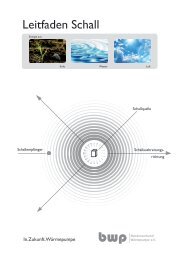
1.1.1. Sound emission<br />
<strong>TERRA</strong> heat pumps are very quiet in operation thanks<br />
to their design. It is however important that the site of<br />
the heater is situated as far as possible from noisesensitive<br />
living areas. A noise-insulating door should<br />
be fi tted door.<br />
1.1.2. Construction drying/screed heating<br />
The heat pump is not designed for the increased<br />
heat requirements when drying out construction work<br />
or heating plaster or screed. This must be covered<br />
by equipment to be provided by the customer if required.<br />
1.1.3. Servicing and maintenance<br />
Regular maintenance as well as checking and servicing<br />
of all system components guarantee its safe and<br />
economical operation in the long term. To achieve<br />
this, we recommend a maintenance contract <strong>with</strong> the<br />
relevant IDM customer service company.<br />
1.1.4. Cleaning<br />
If necessary, the <strong>TERRA</strong> heat pump can be cleaned<br />
<strong>with</strong> a damp cloth. The use of cleaning agents is not<br />
recommended.<br />
4<br />
Operating Manual NAV 1.0<br />
T HE POWER FAMILY<br />
Please strictly observe the safety instructions<br />
in this regard to avoid hazards and<br />
injury to people and material damage.<br />
1.1.5. Working on the equipment<br />
Assembly, initial commissioning, inspection, maintenance<br />
and repairs must only be performed by authorised<br />
specialist staff.<br />
Heat pumps may only be installed by competent specialist<br />
staff and commissioned by a customer service<br />
company trained to do so by IDM-Energiesysteme<br />
GmbH. When working on the heat pump, it must be<br />
deactivated and secured against reactivation. When<br />
working on the heat pump, all safety instructions<br />
in the relevant documentation, stickers on the heat<br />
pump itself and all other applicable safety regulations<br />
must be observed.<br />
1.1.6. In the event of hazards<br />
Immediately disconnect the system from the mains,<br />
e.g. using a separate fuse or a main switch. In the<br />
case of fi re use suitable fi re extinguishers.<br />
1.1.7. Refrigerant leak<br />
The heat pump is fi lled <strong>with</strong> a non-toxic and nonfl<br />
ammable refrigerant. If there is damage however,<br />
refrigerant could leak and lead to oxygen deprivation.<br />
Moreover, open fi re can also lead to harmful decomposition<br />
products. As such, upon the immediate<br />
detection of refrigerant leak (smell) leave the installation<br />
location immediately and close the door. Notify<br />
customer service.<br />
(C) IDM ENERGIESYSTEME GMBH
T HE POWER FAMILY<br />
1.1.8. Installing additional components<br />
The installation of additional components which<br />
have not been tested <strong>with</strong> the equipment may impair<br />
function. No liability is accepted and the guarantee<br />
becomes void in the event of damage caused for this<br />
reason.<br />
1.1.9. Installation room conditions<br />
- Suffi cient ventilation<br />
- No heavy dust formation<br />
- No persistent air humidity<br />
- Frost-proof<br />
1.2. Navigator Control for <strong>HGL</strong> Technology<br />
The following functional description is applicable to<br />
IDM heat pumps type <strong>TERRA</strong> <strong>HGL</strong> <strong>with</strong> installed hot<br />
gas heat exchanger and Navigator Control.<br />
A prerequisite for the perfect operation of the control<br />
system is clean work by the heating engineer and<br />
electrician, as well as the proper commissioning of the<br />
control system by a trained IDM service engineer.<br />
The Navigator Control conforms to the EU Directives:<br />
- 73/23/EC "Low voltage directive"<br />
- 93/68/EC "Electromagnetic compatibility directive"<br />
- EN 61000-6-2 "Electromagnetic compatibility -<br />
resistance"<br />
- EN 61000-6-3 "Electromagnetic comparability -<br />
interference transmission"<br />
- EN 61000-3-2 "Limit values for harmonic current<br />
emissions"<br />
- EN 61000-3-3+A1 "Limitation of voltage fl uctuations"<br />
1.3. Structure of the Navigator Control<br />
Description<br />
The Navigator Control is comprised of a central unit<br />
and the control unit. Furthermore, in accordance <strong>with</strong><br />
requirements, an internal heating circuit expansion<br />
module for two additional heating circuits, as well as<br />
an external heating circuit expansion module for three<br />
additional heating circuits, can be connected. The<br />
central unit also has an interface for a GSM module<br />
as well as a stepper motor module.<br />
Via an SD card slot, on the actual central unit, it is<br />
possible to carry out evaluations using an event log.<br />
(C) IDM ENERGIESYSTEME GMBH Operating Manual NAV 1.0 5<br />
1<br />
2<br />
3<br />
4<br />
5<br />
6<br />
7<br />
8<br />
9<br />
10<br />
11<br />
12<br />
13<br />
Description
1<br />
2<br />
3<br />
4<br />
5<br />
6<br />
7<br />
8<br />
9<br />
10<br />
11<br />
12<br />
13<br />
Operation<br />
2. Allgemeine Operation Beschreibung<br />
2.1. Operation using the Control Unit<br />
The heat pump is put into operation via the main<br />
switch. After actuating the main switch, the Navigator<br />
Control starts automatically.<br />
In systems that are already confi gured the main menu<br />
appears on the LCD after initialisation.<br />
The operation of the Navigator Control is performed<br />
using the control unit. The control unit enables easy<br />
menu-driven operation on the LCD using 6 membrane<br />
keys.<br />
6<br />
F1<br />
By using both arrow keys it is possible<br />
to move between the individual menu<br />
items. The symbol currently selected<br />
has a black background.<br />
By using the selection keys to the left and<br />
right of the arrow keys, the command<br />
<strong>with</strong> the black background at the top of<br />
the LCD can be executed.<br />
Using the F1 key, it is possible to change<br />
between the status displays on the righthand<br />
edge of the screen. The status displays<br />
will be described in greater detail<br />
further ahead.<br />
2.2. Displays in the Main Menu<br />
In the main menu the fi ve submenus are shown by<br />
way of symbols. By using the arrow keys it is possible<br />
to select the individual menu symbols. The submenus<br />
are described in greater detail further ahead.<br />
The heat pump status is shown on the status display<br />
on the right-hand screen edge. Using the F1 key it is<br />
possible to change between the individual status bars<br />
HC(), Info and System.<br />
F2<br />
Operating Manual NAV 1.0<br />
NAVIGATOR 1.0<br />
F1<br />
F2<br />
T HE POWER FAMILY<br />
Using the F2 key, the system can be<br />
switched off or switched on again respectively.<br />
(C) IDM ENERGIESYSTEME GMBH
T HE POWER FAMILY<br />
2.3. Displays in the Status Bar<br />
Info status bar<br />
System status bar<br />
Heating circuit status bar<br />
Description of symbols<br />
q<br />
q<br />
�<br />
Current outside temp.<br />
Mean outside temp.<br />
Current time<br />
Current date<br />
Buffer tank temperature<br />
Cold reservoir temperature<br />
Hygienik temperature<br />
Flow temp. heat pump<br />
Heat source temp.<br />
Heat pump in priority mode<br />
Heating stage<br />
Room temp. set value<br />
Room temp. real value or<br />
status room thermostat<br />
Flow temp. set value<br />
Flow temp. real value<br />
Heating circuit in heating mode<br />
Operation according to the heating<br />
program<br />
Thermostat open - HC pump off<br />
Thermostat closed - HC pump on<br />
System / heating circuit in heating mode<br />
(C) IDM ENERGIESYSTEME GMBH Operating Manual NAV 1.0 7<br />
�<br />
1<br />
Operation<br />
In the Info status bar, the current outside temperature<br />
is displayed on the outside sensor. The mean outside<br />
temperature is calculated over a period of time<br />
(usually 16 hours). Furthermore, the current time and<br />
the date are shown.<br />
In the System status bar, the temperatures for the<br />
buffer tank, cold reservoir, Hygienik, heat pump fl ow<br />
and heat source are displayed. In cascade systems,<br />
the heating stage shows the number of stages in<br />
operation.<br />
In the heating circuit status bar the most important<br />
data for the individual heating circuits are listed.<br />
An individual status bar is displayed for each parameterised<br />
heating circuit. The status bar header shows<br />
which heating circuit is currently activated.<br />
Pump heating circuit in operation<br />
Mixer heating circuit open<br />
Mixer heating circuit closed<br />
Priority mode<br />
Party function - active Holiday function - active<br />
Heating circuit permanent in normal mode<br />
Symbol for cooling mode<br />
Temperature values are only shown for<br />
those devices that are confi gured in the<br />
engineer level.<br />
Heating circuit permanent in ECO mode<br />
Heating stage 1<br />
1<br />
2<br />
3<br />
4<br />
5<br />
6<br />
7<br />
8<br />
9<br />
10<br />
11<br />
12<br />
13<br />
Operation
1<br />
2<br />
3<br />
4<br />
5<br />
6<br />
7<br />
8<br />
9<br />
10<br />
11<br />
12<br />
13<br />
Operating modes<br />
3. Allgemeine Operating modes Beschreibung<br />
3.1. Operating Modes via the Main Menu<br />
The individual heating circuits can be parameterised<br />
via the submenu "Operating Modes".<br />
In order to access the "Operating Modes" menu, use<br />
the arrow keys to select the symbol for operating<br />
modes in the main menu. As soon as the symbol has<br />
a black background, it is possible to open the respective<br />
subprogram by using the right-hand selection<br />
key.<br />
In the operating mode menu, the operating modes of<br />
the system in the individual heating circuits can be<br />
selected.<br />
By using the arrow keys it is possible to move between<br />
the menu items. The current set status is always displayed<br />
(e.g. operating mode System - Automatic) on<br />
the right next to the operating function.<br />
In order to carry out a setting, the desired menu<br />
item (e.g. operating mode System) must have a<br />
black background. The respective submenu can be<br />
accessed by using the right-hand selection key. It is<br />
possible to return to the superordinate menu using<br />
the left-hand selection key and the command "Back".<br />
Depending on the parameterisation of the heat pump,<br />
only the heating circuits using the operating mode<br />
menu are shown.<br />
8<br />
Operating Manual NAV 1.0<br />
T HE POWER FAMILY<br />
(C) IDM ENERGIESYSTEME GMBH
T HE POWER FAMILY<br />
3.1.1. System operating mode<br />
In the submenu for the System operating mode it is<br />
possible to select between the functions Off, Automatic<br />
and Tapwater. Usually the Automatic function is<br />
set. The arrow keys are used to change between the<br />
operating modes.<br />
Operating modes<br />
System operating modes parameters<br />
Par. No. Name Description<br />
PROGO Off The heat pump is not in operation unless the frost-proof function is active.<br />
PROGO Automatic The heat pump runs in the heating mode in accordance <strong>with</strong> the set heating<br />
times.<br />
PROGO Hot water The heat pump only runs for storage tank charging <strong>with</strong>out heating mode.<br />
PROGO Tapwater charging once The heat pump performs the one storage tank charging procedure. After comple-<br />
only<br />
tion of the storage tank charging, the heat pump continues to run in the previous<br />
operating mode.<br />
3.1.2. Holiday program<br />
In the holiday program submenu it is possible to set<br />
a date range during which the heating and cooling<br />
circuits can be operated in the ECO mode. During<br />
this time, no storage tank charging is carried out.<br />
After the set holiday program has elapsed, all the<br />
consumers are administered in accordance <strong>with</strong> the<br />
timer program.<br />
The date for the holiday program can be set by using<br />
the right-hand selection key and the arrow keys. After<br />
completing the setting, the date is saved using the<br />
right-hand selection key.<br />
3.1.3. Party function<br />
The consumers are controlled by the ECO mode up<br />
to the end date / time entered.<br />
The setting is carried out using the right-hand selection<br />
key and the arrow keys. After completing the setting,<br />
the date and time are saved using the right-hand<br />
selection key.<br />
The party function is only active if the individual<br />
heating and cooling circuits are set<br />
to automatic (timer program).<br />
(C) IDM ENERGIESYSTEME GMBH Operating Manual NAV 1.0 9<br />
1<br />
2<br />
3<br />
4<br />
5<br />
6<br />
7<br />
8<br />
9<br />
10<br />
11<br />
12<br />
13<br />
Operating modes
1<br />
2<br />
3<br />
4<br />
5<br />
6<br />
7<br />
8<br />
9<br />
10<br />
11<br />
12<br />
13<br />
Operating modes<br />
3. Allgemeine Beschreibung<br />
Operating modes<br />
3.1.4. HC mode<br />
All parameterised heating circuits are shown in the<br />
operating modes menu. It is possible to change<br />
between operating modes for the respective heating<br />
circuits using the arrow keys.<br />
10<br />
Operating Manual NAV 1.0<br />
T HE POWER FAMILY<br />
Heating circuit operating modes parameters<br />
Par. No. Name Description<br />
HC..01 Off The heating circuit is not in operation unless the frost-proof function is active.<br />
HC..01 Timer program The heating circuit is operated according to the set heating times <strong>with</strong> Day set<br />
room temperature. Four heating times can be set per day for the heating circuit.<br />
HC..01 Normal The heating circuit is operated constantly <strong>with</strong> the Normal Heating set room<br />
temperature.<br />
HC..01 ECO The heating circuit is operated constantly <strong>with</strong> the ECO Heating set room<br />
temperature.<br />
HC..01 Manual heating The outside temperature for the calculation of the individual heating circuits is<br />
replaced <strong>with</strong> 7°C.<br />
(C) IDM ENERGIESYSTEME GMBH
T HE POWER FAMILY<br />
4.1. Temperature Settings via the Main Menu<br />
The temperatures for fresh water capture can be set<br />
using the second menu item in the main menu, as<br />
well as the temperatures for the individual heating<br />
circuits.<br />
4.1.1. Fresh water temperature setting<br />
Fresh water temperature parameters<br />
Par.<br />
No.<br />
Name Description<br />
4. Temperature Settings<br />
FW30 Fresh water temperature The fresh water temperature gives the set temperature for the tapwater capture.<br />
It is possible to carry out this setting over the temperature range from 35.00°C<br />
to 60.00°C. The desired set temperature is set using the arrow keys. The new<br />
temperature value is confi rmed by using the right-hand selection key.<br />
4.1.2. Heating circuits temperature setting<br />
The parameters that can be set for the heating circuit<br />
temperatures are in accordance <strong>with</strong> the machine<br />
confi guration. Only the setting parameters that are<br />
relevant <strong>with</strong> regard to the machine confi guration are<br />
displayed.<br />
Heating circuit temperatures parameters<br />
Par.<br />
No.<br />
Name Description<br />
HC104 Normal Heating Room<br />
Temp.<br />
HC105 ECO Heating Room<br />
Temperature<br />
Upon delivery of the equipment, the default value is set at 46.00°C.<br />
Note: 60°C is only possible for heat pumps using the refrigerant R134a.<br />
The Normal Heating Room Temperature can be set between 15.00°C and 30.00°C.<br />
The duration during which the temperature is maintained depends on the respective<br />
heating program.<br />
The ECO Heating Room Temperature gives the temperature outside the selected<br />
heating times.<br />
The ECO Heating Room Temperature can be set between 10.00°C and 25.00°C.<br />
(C) IDM ENERGIESYSTEME GMBH Operating Manual NAV 1.0 11<br />
1<br />
2<br />
3<br />
4<br />
5<br />
6<br />
7<br />
8<br />
9<br />
10<br />
11<br />
12<br />
13<br />
Temperature Settings
1<br />
2<br />
3<br />
4<br />
5<br />
6<br />
7<br />
8<br />
9<br />
10<br />
11<br />
12<br />
13<br />
Temperature Settings<br />
4. Allgemeine Beschreibung<br />
Temperature Settings<br />
Heating circuit temperatures parameters<br />
Par.<br />
No.<br />
Name Description<br />
12<br />
Operating Manual NAV 1.0<br />
T HE POWER FAMILY<br />
HC108 Heating limit For mixer and uncontrolled heating circuits a heating limit can be set in the user menu<br />
above which the heating mode is blocked.<br />
HC109 Room infl uence<br />
Above this outside temperature, no further heating demand is generated by the<br />
heating circuit. The heating limit is deactivated <strong>with</strong> the setting 0.<br />
The room infl uence factor shows to what extent the control system reacts to the room<br />
temperature.<br />
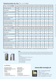
HC110 Heating curve<br />
If the room unit is assembled in a room affected by other heat sources (e.g. a tiled<br />
stove) a smaller proportion should be selected. The temperature of the room in which<br />
the room unit is assembled, also affects the heating of the other rooms.<br />
Note: Parameter is only visible in the case of confi gured room unit.<br />
Given the steepness of the characteristic heating curve, the relation of the outside<br />
temperature to the required fl ow temperature is established.<br />
HC150 Normal Cooling Room<br />
Temp.<br />
HC151 ECO Cooling Room<br />
Temp.<br />
2,6<br />
2,4<br />
2,2<br />
2<br />
The greater the steepness of the characteristic curve is set, the higher the fl ow<br />
temperature for the heating depending on the outside temperature as well as on the<br />
heating and cooling limits.<br />
Parameter for the desired room temperature during Normal Cooling mode.<br />
Parameter for the desired room temperature during ECO Cooling mode.<br />
HC153 Cooling fl ow Parameter for the desired cooling circuit fl ow temperature.<br />
HC154 Dew-point gap This shows the minimum temperature difference between the dew-point (room humidity<br />
sensor) and the set fl ow temperature.<br />
HC108 Cooling limit Below this outside temperature no further cooling demand is generated by the<br />
cooling circuit.<br />
1,8<br />
Outside temperature [°C]<br />
1,6<br />
1,4<br />
1,2<br />
1<br />
0,8<br />
0,6<br />
0,4<br />
(C) IDM ENERGIESYSTEME GMBH<br />
65<br />
60<br />
55<br />
50<br />
45<br />
40<br />
35<br />
30<br />
25<br />
20<br />
[°C]<br />
Flow temperature
T HE POWER FAMILY<br />
5.1. Time Settings via the Main Menu<br />
All time settings can be carried out on the control<br />
system under the third menu item.<br />
5.1.1. Date and time<br />
The date and time can be set in the submenu<br />
"Times".<br />
In order to carry out the setting, "Date/Time" must<br />
be selected from the Times - Menu. The respective<br />
submenu can be accessed by using the right-hand<br />
selection key.<br />
In the "Date and Time" menu, in order to carry out the<br />
setting, the right-hand selection key must be used to<br />
select the function "Change".<br />
Subsequently, the arrow keys can be used to modify<br />
the respective established value. The next setting<br />
value can be accessed by using the right-hand selection<br />
key.<br />
Once all values have been set, the new setting can<br />
be saved using the right-hand selection key.<br />
The changeover between summertime and wintertime<br />
is automatically carried out by the control system.<br />
5. Time Settings<br />
(C) IDM ENERGIESYSTEME GMBH Operating Manual NAV 1.0 13<br />
1<br />
2<br />
3<br />
4<br />
5<br />
6<br />
7<br />
8<br />
9<br />
10<br />
11<br />
12<br />
13<br />
Time Settings
1<br />
2<br />
3<br />
4<br />
5<br />
6<br />
7<br />
8<br />
9<br />
10<br />
11<br />
12<br />
13<br />
Time Settings<br />
5. Allgemeine Beschreibung<br />
Time Settings<br />
5.1.2. Program priority setting<br />
By using the time setting "Program Priority", times<br />
can be established during which a priority storage<br />
tank charging takes place. The storage tank charging<br />
is preferentially carried out prior to heating up the<br />
heating circuits.<br />
During the priority charging procedure, the heating,<br />
when operating <strong>with</strong> a Hygienik, is not supplied <strong>with</strong><br />
heat. When using an additional buffer accumulator,<br />
the supply to the heating circuits is guaranteed via the<br />
additional buffer accumulator in the priority charging<br />
mode.<br />
During the priority charging procedure, the speed<br />
of the charging pump and, as such, the throughput<br />
through the condenser and the <strong>HGL</strong> exchanger, is<br />
reduced to the extent that the accumulator is once<br />
again charged <strong>with</strong> the desired <strong>HGL</strong> temperature<br />
(e.g. 58°C).<br />
Procedure for setting the time:<br />
It is possible to set an arbitrary number of times for<br />
the priority charging for each weekday.<br />
Under the menu item Program Priority it is possible<br />
to change between the individual functions via the<br />
left-hand selection button. The respective function is<br />
selected using the right-hand selection key.<br />
Once the desired day has been chosen, the left-hand<br />
selection key is used to select the Change function.<br />
By using the right-hand selection key, the time for<br />
Activ (priority charging) and Inactiv (no priority charging)<br />
can be set.<br />
14<br />
Operating Manual NAV 1.0<br />
T HE POWER FAMILY<br />
(C) IDM ENERGIESYSTEME GMBH
T HE POWER FAMILY<br />
Setting the times using the cursor:<br />
The Cursor function is selected by using the righthand<br />
selection key. The current status for the cursor<br />
is displayed directly above the right-hand selection<br />
key.<br />
Position Cursor - The cursor can be displaced along<br />
the time bar <strong>with</strong>out having any effect<br />
Cursor Activ - The cursor marks the time range for<br />
"Priority charging". By displacing the cursor <strong>with</strong> the<br />
arrow keys the bar above has a dark background.<br />
Cursor Inactiv - The cursor marks the time range<br />
for "No Priority charging". By displacing the cursor<br />
<strong>with</strong> the arrow keys the bar above has a light background.<br />
The times for Activ or Inactiv can be arbitrarily set.<br />
Copying the settings to another day:<br />
The settings can be copied to another day. To do so<br />
the day to be copied must be active. By using the<br />
left-hand selection key the Copy function is selected<br />
and the right-hand selection key is used to carry out<br />
the action. Subsequently, the desired day to which<br />
the settings are to be copied is selected. By using the<br />
left-hand selection key the Paste function is selected<br />
and the right-hand selection key is used to carry out<br />
the action.<br />
Time Settings<br />
(C) IDM ENERGIESYSTEME GMBH Operating Manual NAV 1.0 15<br />
1<br />
2<br />
3<br />
4<br />
5<br />
6<br />
7<br />
8<br />
9<br />
10<br />
11<br />
12<br />
13<br />
Time Settings
1<br />
2<br />
3<br />
4<br />
5<br />
6<br />
7<br />
8<br />
9<br />
10<br />
11<br />
12<br />
13<br />
Time Settings<br />
5. Allgemeine Beschreibung<br />
Time Settings<br />
5.1.3. Heating circuit program setting<br />
In the "Program HC .." the times for the heating mode<br />
of the heating circuits to be parameterised can be<br />
set.<br />
For each heating circuit, it is possible to set up to<br />
24 heating times for each day selected. The setting<br />
for the heating times is carried out as described for<br />
setting the times in Program Priority mode.<br />
Normal - dark bar - Heating mode at room temp.<br />
Normal Heating<br />
ECO - light bar - Heating mode at room temp. ECO<br />
Heating<br />
5.1.4. Setting EVU blocking time<br />
The blocking time must be maintained by the respective<br />
EVU. It can be set in the menu "EVU Blocking<br />
Time". The entered blocking time is applicable to each<br />
day.<br />
These times can be set to a min. time interval of<br />
0.5 hours.<br />
16<br />
Operating Manual NAV 1.0<br />
T HE POWER FAMILY<br />
(C) IDM ENERGIESYSTEME GMBH
T HE POWER FAMILY<br />
5.1.5. Fan speed reduction in the CL version<br />
The fan speed reduction can be set for Terra CL heat<br />
pumps. By using the fan speed reduction function,<br />
times can be set during which the fan speed on the<br />
evaporator is reduced.<br />
The reduced speed is set by the manufacturer and<br />
can only be modifi ed by customer service.<br />
Time Settings<br />
(C) IDM ENERGIESYSTEME GMBH Operating Manual NAV 1.0 17<br />
1<br />
2<br />
3<br />
4<br />
5<br />
6<br />
7<br />
8<br />
9<br />
10<br />
11<br />
12<br />
13<br />
Time Settings
1<br />
2<br />
3<br />
4<br />
5<br />
6<br />
7<br />
8<br />
9<br />
10<br />
11<br />
12<br />
13<br />
Information<br />
6. Allgemeine InformationBeschreibung<br />
6.1. Information via the Main Menu<br />
Under the fourth menu item of the main menu, various<br />
status requests regarding the system can be made.<br />
6.1.1. Inputs / outputs<br />
Via the Inputs / Outputs Menu, the status of all inputs<br />
(sensors, digital inputs), as well as the status of the<br />
outputs ( analogue outputs, digital outputs) can be<br />
requested.<br />
The status request can be helpful during start-up as<br />
well as when solving errors.<br />
Requests Inputs / Outputs<br />
Par.<br />
No.<br />
Name Description<br />
- Sensor Current temperatures of the respective sensor in °C<br />
- Digital inputs Status of the digital inputs (O- Open, C - Closed)<br />
- Analogue outputs Display of the voltage at the outputs (0-10V)<br />
18<br />
Bedienungsanleitung NAV 1.0<br />
T HE POWER FAMILY<br />
- Digital outputs<br />
Display of the modulation in %<br />
Status (Off - On)<br />
- Bus connection This is where the current status of the cascades CAN - Bus participants is displayed.<br />
6.1.2. System information<br />
In the submenu System Information, the current<br />
software version, as well as the total times for the<br />
individual operating modes, the running times for<br />
the heating stages and the switching signals of the<br />
heating stages that have been performed by the heat<br />
pump are shown in hours.<br />
(C) IDM ENERGIESYSTEME GMBH
T HE POWER FAMILY<br />
6.1.3. Heat meter<br />
If a heat meter is installed, under the menu item<br />
Heat Meter it is possible to request the heating and<br />
cooling performance in [kW]. Furthermore, the current<br />
actual performance of HP fl ow and <strong>HGL</strong> fl ow is<br />
shown in [W].<br />
6.1.4. GSM Module<br />
Via the submenu "GSM Module“ the current status,<br />
as well as the signal quality, is displayed via the GSM<br />
antenna.<br />
The GSM Module allows storing three mobile phone<br />
numbers which, in the event of failure, can be reported<br />
via SMS (see operating instructions GSM Module).<br />
If no GSM Module is installed, No is displayed at<br />
"SMS Modul Ready".<br />
The SimCard State parameter provides the current<br />
status of the SimCard. When operating correctly,<br />
SimCard State 3 is displayed.<br />
0 ..... Initialisation<br />
1 ..... SimCard not used<br />
2 ..... SimCard used<br />
3 ..... SimCard ready<br />
4 ..... SimCard error<br />
5 ..... PIN OK - initialisation<br />
6 ..... PIN request not deactivated<br />
Before the SimCard can be used the PIN<br />
request must be deactivated via a mobile<br />
phone.<br />
Information<br />
(C) IDM ENERGIESYSTEME GMBH Bedienungsanleitung NAV 1.0 19<br />
1<br />
2<br />
3<br />
4<br />
5<br />
6<br />
7<br />
8<br />
9<br />
10<br />
11<br />
12<br />
13<br />
Information
1<br />
2<br />
3<br />
4<br />
5<br />
6<br />
7<br />
8<br />
9<br />
10<br />
11<br />
12<br />
13<br />
Faults<br />
7. Allgemeine Faults Beschreibung<br />
7.1. Error Display in the Main Menu<br />
When an error occurs an error notifi cation is shown<br />
on the display.<br />
Via the left-hand selection key it is possible to access<br />
the submenu Error where a more detailed description<br />
of the error is given.<br />
Sensor error<br />
Error<br />
No.<br />
Designation Description<br />
100 Outside sensor (B32) Short circuit<br />
101 Interruption<br />
102 Heat pump fl ow sensor (B33) Short circuit<br />
103 Interruption<br />
104 <strong>HGL</strong> fl ow sensor (B35) Short circuit<br />
105 Interruption<br />
106 Heat source sensor (B36) Short circuit<br />
107 Interruption<br />
108 Heat accumulator sensor (B39) Short circuit<br />
109 Interruption<br />
110 Cold reservoir sensor (B40) Short circuit<br />
111 Interruption<br />
112 Hygienik sensor (B41) Short circuit<br />
113 Interruption<br />
114 Fresh water station sensor (B42) Short circuit<br />
115 Interruption<br />
116 Flow sensor HC A (B51) Short circuit<br />
117 Interruption<br />
118 Flow sensor HC B (B52) Short circuit<br />
119 Interruption<br />
120 Room sensor HCA (B61) Short circuit<br />
121 Interruption<br />
122 Room sensor HCB (B62) Short circuit<br />
123 Interruption<br />
126 Room humidity sensor (B31) Short circuit<br />
127 Interruption<br />
20<br />
Operating Manual NAV 1.0<br />
T HE POWER FAMILY<br />
(C) IDM ENERGIESYSTEME GMBH
T HE POWER FAMILY<br />
Sensor error<br />
Error<br />
No.<br />
Designation Description<br />
130 Flow sensor HC C Short circuit<br />
131 Interruption<br />
132 Flow sensor HC D Short circuit<br />
133 Interruption<br />
134 Room sensor HC C Short circuit<br />
135 Interruption<br />
136 Room sensor HC D Short circuit<br />
137 Interruption<br />
138 Flow sensor HC E Short circuit<br />
139 Interruption<br />
140 Flow sensor HC F Short circuit<br />
141 Interruption<br />
142 Flow sensor HC G Short circuit<br />
143 Interruption<br />
144 Room sensor HC E Short circuit<br />
145 Interruption<br />
146 Room sensor HC F Short circuit<br />
147 Interruption<br />
148 Room sensor HC G Short circuit<br />
149 Interruption<br />
System error<br />
Error<br />
No.<br />
Designation Description<br />
Faults<br />
020 Heat pump fl ow maximum temperature Heat pump fl ow temperature is above the set maximum temperature.<br />
021 Heat pump fl ow minimum temperature Heat pump fl ow temperature is below the set minimum temperature.<br />
022 Low pressure switch The low pressure switch has switched off the heat pump (< 3 times<br />
in 24h).<br />
023 Low pressure lock pressure fault The low pressure switch has switched off the heat pump (> 3 times<br />
in 24h). The heat pump is no longer triggered.<br />
024 High pressure switch The high pressure switch has switched off the heat pump (< 3 times<br />
in 24h).<br />
025 High pressure lock pressure fault The high pressure switch has switched off the heat pump (> 3 times<br />
in 24h). The heat pump is no longer triggered.<br />
(C) IDM ENERGIESYSTEME GMBH Operating Manual NAV 1.0 21<br />
1<br />
2<br />
3<br />
4<br />
5<br />
6<br />
7<br />
8<br />
9<br />
10<br />
11<br />
12<br />
13<br />
Faults
1<br />
2<br />
3<br />
4<br />
5<br />
6<br />
7<br />
8<br />
9<br />
10<br />
11<br />
12<br />
13<br />
Faults<br />
7. Allgemeine Beschreibung<br />
Faults<br />
System error<br />
Error<br />
No.<br />
Designation Description<br />
22<br />
Operating Manual NAV 1.0<br />
T HE POWER FAMILY<br />
026 Flow monitoring The fl ow switch in ground water systems has switched off the heat<br />
pump (< 3 times in 24h).<br />
027 Flow lock The fl ow switch in ground water systems has switched off the heat<br />
pump (> 3 times in 24h). The heat pump is no longer triggered.<br />
028 Start-up current limiter see LED Error start-up current limiter (< 5 times in 24h). The type of error is<br />
displayed on the start-up current limiter.<br />
029 Start-up current limiter 5x in 24h Error start-up current limiter (> 5 times in 24h). The heat pump is no<br />
longer triggered.<br />
030 Motor protection heat source pump The motor protection for the heat source pump has been triggered<br />
(< 5 times in 24h).<br />
031 Motor protection heat source 5x in 24h The motor protection for the heat source pump has been triggered<br />
(> 5 times in 24h). The heat pump is no longer triggered.<br />
032 Maximum defrosting time exceeded The maximum defrosting time has been exceeded<br />
033 Minimum condenser temperature undershot<br />
The heat pump has been switched off due to undershooting the minimum<br />
condenser temperature.<br />
034 Fan error The control system for the fan has detected a functional error.<br />
036 Electric immersion heater overheating The safety thermostat of the immersion heater has been activated.<br />
050 Dew-point monitoring device has been<br />
activated<br />
The heat pump has been switched off by the dew-point monitoring<br />
device.<br />
060 Heat source temperature The measured heat source outlet temperature undershoots the<br />
minimum heat source temperature.<br />
061 Warning heat source temperature The heat source outlet temperature reaches a critical value min. heat<br />
source temperature + 2K<br />
(C) IDM ENERGIESYSTEME GMBH
Notes<br />
T HE POWER FAMILY<br />
Notes<br />
(C) IDM ENERGIESYSTEME GMBH Operating Manual NAV 1.0 23<br />
1<br />
2<br />
3<br />
4<br />
5<br />
6<br />
7<br />
8<br />
9<br />
10<br />
11<br />
12<br />
13
Always there for you.<br />
Your IDM partner<br />
ONE STEP AHEAD*<br />
T HE POWER FAMILY<br />
IDM - service technology<br />
IDM Academy<br />
IDM HEADQUARTERS IN EASTERN TYROL, AUSTRIA<br />
IDM ENERGIESYSTEME GMBH<br />
Seblas 16 – 18 A-9971 Matrei in Osttirol, Austria<br />
Telephone +43(0)4875.6172 - 0 Fax +43(0)4875.6172 - 85<br />
E-mail team@idm-energie.at<br />
www.idm-energie.com<br />
THE POWER FAMILY<br />
COMMISSIONING – SERVICING – ON-SITE SERVICE<br />
Our service technicians are happy to help on-site. Contact<br />
details for your regional customer service centre can be<br />
found on our website www.idm-energie.com.<br />
PRACTICAL KNOWLEDGE FOR SALES AND TECHNOLOGY<br />
The comprehensive range of seminars for specialists at the<br />
IDM POWER FAMILY is available to you at all times on our<br />
website www.idm-energie.com. We look forward to<br />
receiving your registration.<br />
© IDM ENERGIESYSTEME GMBH Matrei i. Osttirol 10.06.09 · Errors and omissions excepted