Operation and Maintenance Manual for GENTEC® Model 881VR ...
Operation and Maintenance Manual for GENTEC® Model 881VR ...
Operation and Maintenance Manual for GENTEC® Model 881VR ...

Create successful ePaper yourself
Turn your PDF publications into a flip-book with our unique Google optimized e-Paper software.
<strong>Operation</strong> <strong>and</strong> <strong>Maintenance</strong> <strong>Manual</strong> <strong>for</strong>GENTEC ® <strong>Model</strong> <strong>881VR</strong>Continuous/Intermittent Digital Suction RegulatorsGenstar Technologies Co., Inc.4525 Edison AvenueChino, CA 91710 USATEL 909-606-2726FAX 909-606-6485CAUTION: United States Federal law restricts thisdevice to sale by or on the order of a physician.
IMPORTANT SAFETY INSTRUCTIONS.READ AND UNDERSTAND THESE INSTRUCTIONSCOMPLETELY BEFORE OPERATING THISEQUIPMENT.If you do not underst<strong>and</strong> any of these instructions, or if you haveany questions regarding the use of this product, please contact yourfacility’s training manager, your supervisor, the medical equipmentdealer from whom the product was purchased, or the manufacturerbe<strong>for</strong>e operating the equipment.Do not attempt to repair this device if you have not been properlytrained. Doing so may create a hazardous situation that may resultin death or serious injury. Attempted repair by anyone other than aduly authorized repair/service center of Genstar Technologies Co.,Inc. voids any <strong>and</strong> all warranties, express or implied.Carefully inspect <strong>and</strong> test this product be<strong>for</strong>e each use to ensureproper operation. Do not use the product if there are signs ofdamage or if it does not pass the initial suction test.Should this product require repair or service that will requireshipping the product to another location, bear in mind that UnitedStates Federal law restricts the shipping of contaminated products.Refer to DOT regulations <strong>for</strong> additional in<strong>for</strong>mation.Genstar Technologies Co., Inc. (GENTEC ® ) manufactures continuous/intermittent digital suction regulators in two ranges, 0 to 160mmHg(<strong>881VR</strong>-160) <strong>and</strong> 0 to 300mmHg (<strong>881VR</strong>-300). These suction regulatorsprovide three modes: CONT (continuous regulated vacuum), OFF (no vacuum)<strong>and</strong> INT (intermittent regulated vacuum). Please take a few minutes tofamiliarize yourself with the product by reviewing Figure 1 on the next page.The mode is selected by moving the lever at the top of the regulator to the left(CONT) <strong>for</strong> continuous suction, the center (OFF) to turn off the regulator, orthe right (INT) <strong>for</strong> intermittent suction.The CONT mode provides continuous regulated suction levels as set by theuser. The suction level is set by occluding the suction tubing, then adjustingthe regulator knob on the front of the suction regulator to achieve the desiredsuction level, up to the designed range. Suction is increased by turning theregulator knob clockwise, decreased by turning it counter-clockwise.1The OFF mode turns off the suction regulator, allowing no suction at the tubing.The INT mode provides intermittent regulated suction levels as set by the user.The suction level is set by occluding the suction tubing, then making sure the
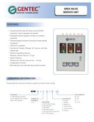
Mode SelectorGaugeRegulatorAdjustment KnobOutlet (in back)Inlet (on bottom)Figure 1 - Main Featuresregulator is in the ON cycle. This could take up to 10 seconds. When theregulator begins the ON cycle, adjust the regulator knob on the front of thesuction regulator to achieve the desired suction level, up to the designedrange. Suction is increased by turning the regulator knob clockwise,decreased by turning it counter-clockwise.A suction filter or vacuum trap assembly (GENTEC catalog #880VT) shouldbe used to prevent aspirate from entering the suction regulator. Typically,the suction catheter is connected to the suction tubing, which is thenconnected to the inlet fitting on the suction canister.The canister can be connected directly to the suction regulator via DISSconnection, or, as is recommended, connected to a filter or vacuum trap,which is then connected to the suction regulator via direct, threadedconnection, suction tubing, or DISS connector (see Figure 2).The appropriate outlet connector (located on the back of the suctionregulator) must be used <strong>for</strong> connection to the wall inlet. The use ofconverting adapters (e.g., DISS connection to Ohio connection) should beavoided. If the suction regulator is connected via tubing or hose assemblyto the wall inlet (as occurs when the suction regulator is attached to a mobilest<strong>and</strong>), a minimum inside hose diameter(ID) of 5/16” (7.9mm) should beused to prevent loss of flow.2
DO NOT connect the suction tubing directly from the patient to either thevacuum trap assembly or the suction regulator. Doing so may permanentlydamage the suction regulator <strong>and</strong> void any <strong>and</strong> all warranties, express or implied.A collection canister (reusable or disposable) MUST be used between thepatient <strong>and</strong> the suction regulator or vacuum trap, if used. If a vacuum trap is notused it is recommended that a disposable hydrophobic bacterial filter be usedbetween the suction canister <strong>and</strong> the suction regulator to prevent overflow ofthe canister into the suction regulator. Use of these filters may also preventbuild up of aerosolized particulate inside the suction regulator, thus reducingmaintenance requirements <strong>and</strong> extending the life of the unit.VERIFYING REGULATOR OPERATIONNOTE: The proper operation of the suction regulator must be verified prior toeach use. Should the regulator not operate in accordance with the following, itmust be repaired by authorized personnel.1) Ensure that the Mode selector is in the OFF (center) position.2) Connect the regulator to a vacuum source (normally the wall-mounted inlet).3) Occlude the regulator inlet, <strong>and</strong> turn the adjustment knob one full turnclockwise.4) Verify that the gauge needle does not move from the “0” position.5) Move the Mode selector to the “CONT” position.6) Occlude the regulator inlet, <strong>and</strong> turn the adjustment knob counter-clockwiseuntil the gauge needle is at 0.7) Keeping the inlet occluded, turn the adjustment knob clockwise. The gaugeneedle should move in a clockwise direction, indicating an increase in thevacuum level. Turning the adjustment knob counter-clockwise shouldreduce the vacuum level, with the gauge needle moving counter-clockwise.8) Occlude the regulator inlet. The regulator should begin the ON cycle within10 seconds, <strong>and</strong> the gauge needle should read the same as the previoussetting.9) The unit should remain the ON cycle <strong>for</strong> 14-18 seconds, then turn OFF <strong>for</strong>6-10 seconds, then back on <strong>for</strong> 14-18 seconds. Verify one complete cycle.10) Move the Mode selector to the “OFF” position. The needle should return to 0.If the regulator passes all of the above, it is ready <strong>for</strong> patient use. Failure ofany of the above requires that the unit be serviced by authorized personnel.Once the operation of the regulator has been verified, it can be prepared <strong>for</strong>patient use as follows:1) Connect the regulator to the wall inlet, ensuring proper latching.2) Move the Mode selector to “CONT” or “INT”.3) Occlude the inlet or tubing.4) Adjust the regulator knob to achieve the desired level of vacuum.5) Attach the suction catheter <strong>and</strong> proceed.NOTE: the suction regulator should always be turned OFF when not in use.This will prevent placing undo dem<strong>and</strong>s on the facility’s central vacuum system.3
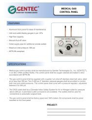
Ohio/OhmedaChemetronDISS Nut & NippleDISS H<strong>and</strong>-TightPossible BackFittingsPuritan-BennettHose BarbPossible Inlet FittingsHose Barb DISS MaleVacuum Trap Assembly or Fitting OnlyFigure 2 - Suction Regulator ConfigurationsDO NOT connect suction tubing directly to the vacuum trap, filter or suction regulator!<strong>881VR</strong> Disassembly Instructions:1) Disconnect the <strong>881VR</strong> from the suction source.2) Sterilize the suction regulator using ETO or autoclave, <strong>for</strong> self-protection.3) Remove the four screws marked by arrows on the back of the unit.4) Turn the regulator adjustment knob counterclockwise to release thefaceplate.5) The gauge can be gently lifted out of the socket.6) The regulator can be gently lifted out of the socket.7) One screw holds the Mode selector lever in place.Reassembly is accomplished by per<strong>for</strong>ming the above steps in reverse order.DO NOT OVERTIGHTEN THE SCREWS WHEN REPLACING.The timing of the intermittent mode can be adjusted by removing the T 0 <strong>and</strong>T - T 12 covers. The T 0 valve controls the OFF time, <strong>and</strong> the T 2 valve controlsthe ON time. These timers should only be adjusted by authorized personnel,at the direction of a physician. Refer to GENTEC publication#<strong>881VR</strong>-TIMING <strong>for</strong> additional in<strong>for</strong>mation regarding timing adjustment.The regulator can be cleaned by wiping the outside surfaces with disinfectant.The internal flow path can be cleaned by suctioning a cold sterilant throughthe unit, then allowing the unit to run <strong>for</strong> 30-45 minutes to dry the interior.Repair assemblies can be purchased from your Authorized GENTECdistributor, refer to the exploded view on page 5 <strong>for</strong> the parts list.All parts are sold in kits of 6.4
No. Part No. Description Qty/Kit1 <strong>881VR</strong>-K01 Adjustment Knob Assembly 62 <strong>881VR</strong>-K02 Front Cover6345610<strong>881VR</strong>-K04<strong>881VR</strong>-K05<strong>881VR</strong>-K05A<strong>881VR</strong>-K07<strong>881VR</strong>-K09<strong>881VR</strong>-K08Lens7 <strong>881VR</strong>-K10 Back Body8 <strong>881VR</strong>-K06 Relief Valve, 0-160 mmHg9NotShownNotShownNotShown<strong>881VR</strong>-K06A<strong>881VR</strong>-K03<strong>881VR</strong>-K03A<strong>881VR</strong>-K11Gauge, <strong>881VR</strong>-K05-D160Gauge, <strong>881VR</strong>-K05-D300Selector Knob AssemblyDrive Plate AssemblyRelief Valve, 0-300 mmHgRegulator Assembly, 0-160 mmHgRegulator Assembly, 0-300 mmHgTimer AssemblyTiming Needle Valve Assembly(2 per suction regulator)<strong>881VR</strong>-K12 Timer Cap, T 0 6<strong>881VR</strong>-K13 Timer Cap, T 1 , T 266666666666665
# Problem Probable Cause123The vacuum gaugeneedle does not moveoff “0” when regulatoris connected tovacuum source.The vacuum regulatorgauge shows areading but there is nosuction at the tubing.Under the regulatorcannot reach thespecified suction level(i.e., 120mmHg or240mmHg, dependingupon model).The regulator is in the “OFF”mode, or is not fully in the“CONT” or “INT” position.The suction regulator is in the“INT” position, <strong>and</strong> has startedin the “OFF” cycle.The adjustment knob is in thefully counter-clockwise, closed,position.The collection bottle or suctiontube is leaking.The collection bottle is too full,causing the float to shut off thesuction.The filters or suction tubing areclogged.Suction source cannot providesufficient suction.RegulatorInternalProblemsRelief valve (F) isdamaged.O-ring on vacuumgauge (B) isdamaged.O-ring in regulatorassembly (E) isdamaged.Regulator assembly(E) is damaged.CorrectiveMeasuresMove the modeselector to the“CONT” or “INT”position.Wait 8-10 seconds<strong>for</strong> the “ON” cycleto start.Turn theadjustment knobclockwise to open.Check thecollection bottle<strong>and</strong> tubing <strong>for</strong> leaks.Empty thecollection bottle.Change the filters<strong>and</strong> tubing.Increase sourceequipment vacuumsettings.Replace relief valve.Replace o-ring.Replace o-ring.Replace regulatorassembly.4Under REG mode thesuction is too strong<strong>and</strong> cannot be reduced.Mode selectorassembly (H) isloose.Gas assist port (6) is clogged.Tighten or replacemode selectorassembly.Clean gas assistport.6
Genstar Technologies Co., Inc.4525 Edison AvenueChino, CA 91710 USATEL 909-606-2726 or 800-333-0811FAX 909-606-6485 or 800-999-1478www.gentechealthcare.comCopyright 2012Form No. 9-OM-<strong>881VR</strong>/0612