elotest m3 - Rohmann GmbH
elotest m3 - Rohmann GmbH
elotest m3 - Rohmann GmbH

Create successful ePaper yourself
Turn your PDF publications into a flip-book with our unique Google optimized e-Paper software.
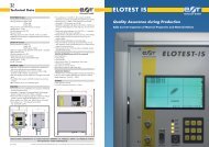
Eddy Current Instruments and -Systems<br />
Hand held and portable dual frequency eddy current<br />
instrument with oversized 5,7“ display<br />
<strong>Rohmann</strong> <strong>GmbH</strong><br />
Additional HD-Rotorfilter for specific ROTOR applications
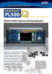
ELOTEST M3 - Examples of applications<br />
Eddy Current Instruments and -Systems<br />
Conductivity measurement in IACSor MS/m<br />
from 1 % up to 110% IACS<br />
Crack detection of hidden defects in aluminium<br />
rivet layers<br />
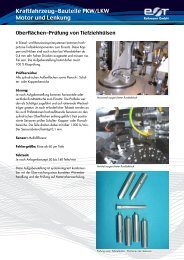
Dual frequency eddy current instrument ELOTEST M3<br />
Dynamic surface crack detection rotor blade Manual surface crack detection<br />
with adapted contour sensor<br />
Charging station M3-LS with Li-Ion<br />
battery pack M3 BA2<br />
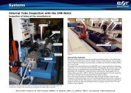
Dual frequency inner tube inspection<br />
with signal-mix function<br />
<strong>Rohmann</strong> <strong>GmbH</strong><br />
Coil for sorting test with screws of different tensile<br />
strengths<br />
Bore hole inspection with mini rotor on aluminium<br />
structures<br />
Test set for rough environmental conditions with<br />
LED-crack indicator on the probe
Technical Data<br />
User-Interface ELOTEST M3<br />
• Pictograph-based operation via key pad with key-click<br />
• 6 languages: English, German, French, Italian, Swedish,<br />
and Spanish<br />
• Direct-function keys for offset- and liftoff-compensation<br />
• Programmable function key<br />
• Intuitive operation using only one submenu-level<br />
• Speed control for rotor (torque compensated) in 10 steps (corresponds to<br />
approx. 900rpm to 2700rpm using <strong>Rohmann</strong> standard rotors)<br />
Probe Connection<br />
• 11-pin Fischer socket, compatible with the 8-pin Fischer connector<br />
• BNC connector for parametric probes (resonant probes)<br />
• OEM probes to be connected via an adapter or directly to the BNC<br />
connector<br />
Activ Probe Compensation<br />
• Compensation of the probe response signal for optimum signal dynamics<br />
• Automatic test frequency selection using the probe characteristics<br />
• Automatic balancing of single-coil probes using fi nely graduated, internal<br />
compensating loads (no external elements required)<br />
Frequency Range<br />
• 10Hz to 12MHz, continuously adjustable, quartz stabilized,<br />
display in Hz, kHz, MHz<br />
• Adjustable driver current to 100% in 2% steps,<br />
(100% ≈ +/-10V at Imax=0.3A)<br />
• Dual-frequency operation in multiplex-mode (on one probe)<br />
Gain<br />
• Preamplifi cation 0 to 60dB in 0.5dB steps (0 to 40dB in 100kHz range)<br />
• Gain 0 to 60dB in 0.5dB steps<br />
• Axis spread 0 to 20dB in 1dB steps<br />
• Automatic selection of preamplifi cation and gain<br />
Phase<br />
• 0-359.5° in 0.5° steps; step size adjustable<br />
Filter<br />
• Low-pass fi lter 1.3Hz to 10kHz in 40 steps<br />
• High-pass fi lter 0Hz to 10kHz in 40 steps<br />
• Band-pass fi lter 0Hz to 10kHz, combination of HP and LP<br />
• Selectable automatic fi lter for rotor operation<br />
• HD-fi lter to optimize the defect classifi cation during rotor inspection (e. g.<br />
distinction crack/corrosion)<br />
LCD – Display<br />
• LCD featuring long-life LED backlight, 120 x 89mm (4.72“ x 3.5“)<br />
• Temperature-compensated contrast setting<br />
• Resolution 320 x 240pixel, refresh rate 75Hz,<br />
• 220.000 data samples/second, no signal delay<br />
• Signal display covering 100% of the screen; over 89% with menu displayed<br />
• 80° viewing angle<br />
Display Modes<br />
• Impedance plane/spot display (X/Y), available for all probes<br />
• Time-base/sweep display (Y/t) 5ms bis 60s in 17 steps, synchronized<br />
• Simultaneous X/Y- and Y/t-display (dual-screen mode)<br />
• Reference signal may be displayed in the background<br />
6<br />
• 2 screen grid sizes with adjustable intensity<br />
• Selectable display range: X/Y center – X/Y center bottom – X/Y center right<br />
• Freely positionable zero point<br />
• Automatic trigger during rotor operation<br />
D<br />
• Simultaneous multi-signal display during multi-frequency operation<br />
• Persistence: 0.1s to 70s adjustable in 12 steps<br />
• On-screen signal storage; cleared manually or via auto-erase (2s - 80s)<br />
Gates/ Alarm<br />
• Alarm: optical and acoustic<br />
• Active in all display modes; may be inverted<br />
• Adjustable gates: +Y-gate, Box-gate, Circle-gate with adjustable fl at in the<br />
C<br />
Y-direction<br />
Parameter Settings/Image Memory<br />
• 99 user settings may be programmed, stored and recalled<br />
• Application-related factory default settings (cannot be overwritten)<br />
• 32 signal memories incl. parameter settings for documentation<br />
• Parameter setups and images may be named using alphanumerical<br />
characters<br />
• Long-term recording (strip chart) of X- and Y-signals, from 20s to 24hrs;<br />
90.000min/max-values (envelope, without data-loss)<br />
• Data storage maintained (backup-battery)<br />
B<br />
Datum Name<br />
Gezeichnet 03.02.2011 Radde<br />
<strong>Rohmann</strong> <strong>GmbH</strong> • Carl-Benz-Str. 23 • 67227 Frankenthal • GERMANY • Tel. +49(0)62 33 - 3789-0 • Fax +49(0)62 33 Kontrolliert - 3789-77<br />
A<br />
www.rohmann.de • E-Mail: info@rohmann.de<br />
Doc. M3/03_2011 All rights reserved. Patent pending. Protection 6 of registered design MR 1.140. As 5part<br />
of the continued development 4we<br />
reserve the right to make technical 3 modifi cations without prior announcement. 2<br />
5<br />
75<br />
196<br />
4<br />
3<br />
240<br />
<strong>Rohmann</strong><br />
<strong>GmbH</strong><br />
Frankenthal<br />
Status Änderungen Datum Name<br />
<strong>Rohmann</strong> <strong>GmbH</strong><br />
Conductivity Measurement<br />
• Measurement in % IACS or MS/m from 1% IACS to 110% IACS<br />
• Measuring frequency 60kHz<br />
• Calibration using 2 individually adjustable calibration points<br />
Coating Thickness Measurement<br />
• Measurement of non-conductive layers on conductive non-ferromagnetic<br />
materials<br />
• Measurement range up to1000µm<br />
Multi-Frequency Operation<br />
• 2-frequency multiplex<br />
• Multiplex rate up to 1kHz<br />
• Both frequencies fully adjustable, independent of each other<br />
• Signal mix-function to suppress unwanted effects<br />
Interfaces<br />
• RS232-interface for PC or printer (HP Laserjet and Epson LX80)<br />
• Bluetooth for wireless communication<br />
Operation with Lithium-Ionen Accu<br />
• Without rotor: approx. 4.5 hrs<br />
• With rotor: approx. 3.5 hrs<br />
• Indication of remaining charge capacity<br />
• Acoustic and optical alarm for low battery<br />
• Charge time Lithium Ion Battery from 0% to 70% - approx. 1 hour<br />
• Charge time Lithium Ion Battery from 0% to 100% - approx. 6 hours<br />
• Accu may be replaced in less than 10 seconds<br />
Ambient Conditions<br />
• Operation between -20°C (-4°F) and 50°C (122°F) at max. 85% rel.<br />
humidity (non-condensating)<br />
• Storage between -30°C (-22°F) and 80°C (176°F) at max. 85% rel.<br />
humidity (non-condensating)<br />
• Accu charge between 0°C (32°F) and 40°C (104°F) at max. 85% rel.<br />
humidity (non-condensating)<br />
Dimensions<br />
• Hight: 180mm<br />
• Width: 200mm<br />
• Depth: 76mm<br />
• Weight: 1.2 kg<br />
Power Supply<br />
• Li-Ion battery (14.8V/1.95Ah) charging time with charging station LS:<br />
approx.. 1.5 hours to 80%, 3 hours to 100%<br />
• Mains operation via wide-range charger (90 - 250VAC)<br />
PC-Software<br />
• Setting Manager PC software to archive parameter settings and to<br />
document screen dumps and inspection protocols<br />
Norm<br />
2<br />
Oberfläche Maßstab: Format:<br />
Freimaßtoleranzen<br />
nach DIN 7168 fein<br />
Werkstoff:<br />
Rohteil:<br />
Benennung:<br />
Prüfgerät ---M3---<br />
Zeichnungsnummer:<br />
1<br />
00M0660000001012<br />
1