Ramsey Silent Chains - tecoStyle
Ramsey Silent Chains - tecoStyle
Ramsey Silent Chains - tecoStyle

You also want an ePaper? Increase the reach of your titles
YUMPU automatically turns print PDFs into web optimized ePapers that Google loves.
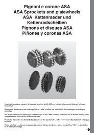
<strong>Ramsey</strong> <strong>Silent</strong> <strong>Chains</strong>For Power Transmission<strong>Ramsey</strong> Products specializes in the design, manufacture,and application of silent chain drives, also known asinverted tooth or toothed chain drives. For more than 80years this has been our focus, and today we remaincommitted to providing our customers with the world'swidest range of top quality silent chain products.Because we specialize in silent chain, we understand howimportant it is to choose the right chain and sprockets foreach application. Whether selecting components for anew application, replacing an existing chain, or customdesigning a chain, our goal is to provide our customerswith the most practical and cost effective solutions. If ajob can be done with silent chain, we will help find thebest chain for the job, at the lowest possible cost.Many companies sell silent chain, but no one offers theproduct range, quality, and support provided by <strong>Ramsey</strong>.In addition to our extensive standard product line, weoffer replacements for most competitors' chains, as wellas custom designed chains. We also provide freeconsultation and drive selection assistance through ourstaff of experienced designers. Whether your requirementis a single chain, or a much larger volume, our sales andengineering staff has the experience to assist you. Withwarehouses and representatives around the world, wewelcome the opportunity to serve you.ABOUT THIS CATALOG<strong>Ramsey</strong> manufactures three different silent chainproduct lines for general power transmission. Each hasunique features and advantages:RPV seriesRPV chain and sprockets are high performanceproducts offering maximum speed and powerhandling capability. RPV is usually the choice forchallenging applications, particularly where space islimited and power or speed requirements exceed thecapacity of other products.RP seriesRP or RamPower silent chain provides approximatelytwo times the power capacity of standard silent chain.RP chain operates on sprockets having an ASMEStandard tooth profile and is well suited for new orreplacement applications.SC seriesSC silent chain and sprockets are manufactured tocomply with the ASME Standard for silent chain. SCproducts have been around the longest, are usedprimarily in replacement applications, and are oftenthe most economical.Many of the products listed in this catalogare successfully employed in applicationsother than power transmission.For additional information regarding othersilent chain applications, such as conveying,or for details on specialty silent chainproducts, please call <strong>Ramsey</strong> or visit ourwebsite: www.ramseychain.com.1
CONTENTS<strong>Silent</strong> Chain Fundamentals............ 2-3Applications.......................................4RPV................................................ 5-7RP................................................ 8-10SC.............................................. 11-14Sprockets................................... 15-21Ordering Information......................22Drive Selection.......................... 23-25Lubrication................................. 26-27Installation.......................................28Connection......................................29Service Factors............................... 30Maintenance and formulas.............. 31WHY SILENT CHAIN?<strong>Silent</strong> chain offers today’s drive designer uniqueadvantages and options for transmitting powersmoothly, efficiently, and economically. Capable oftransmitting loads and speeds that exceed the capacityof all other chains and belts, silent chain providesproven technology that is found in applicationsthroughout modern industry. <strong>Silent</strong> chain alsoproduces very little vibration or noise, and operates atefficiencies as high as 99%. Add to these features awide range of standard chain and sprocket sizes andthe result is an extremely flexible and powerful systemfor power transmission.<strong>Silent</strong> Chain Drives compared with belts1.Significantly higher speeds and power capacity2.Greater efficiency3.Larger ratios possible4.No slippage5.Withstands heavier overloads6.Higher drive ratios at short center distances7.Less affected by temperature or humidity8.Lower bearing loads9.Detachable and therefore more easily installed10.Effective in oil filled gear boxes<strong>Silent</strong> Chain Drives compared with roller chain1.Significantly higher speeds and power capacity2.Much quieter3.Transmits power more smoothly, less vibration4.Lower impact load during sprocket engagement5.Higher efficiency (as high as 99%)6.Longer sprocket life<strong>Silent</strong> Chain Drives compared with gears1.Quieter than spur gears2.Center distance much less restricted3.Shaft parallelism tolerances are broader4.Lower bearing loads5.No end thrust as with helical gears6.Greater elasticity to absorb shockCHAIN CONSTRUCTION<strong>Ramsey</strong> silent chains are made from hardened alloysteel components consisting of flat tooth shapeddriving links, guide links and pins that form the chainjoint. The driving links engage sprocket teeth muchthe way a rack and pinion mesh. Guide links serve toretain the chain on sprockets and pins hold the jointtogether and allow the chain to flex.Driving LinksDriving links, also known as plainlinks, engage sprocket teeth withless sliding and less impact thanother types of chain. This results inquieter operation and longersprocket life. Reduced impactloading also allows for higher operating speeds.Guide LinksGuide links maintain propertracking of the chain on sprockets.They can be positioned on theouter edges of the chain in sideguide or nearer to the middle ofthe chain with center guide. Widerchains will often have two rows of center guide links,commonly referred to as two center guide.Pins and JointsRPV, RP, and SC chains use highly specialized two-pinjoints that have been developed to maximize chainload and speed capacity, while reducing friction andwear. RPV and RP use case hardened "crescent" shapedpins, while SC chains contain the original "D" shaped<strong>Ramsey</strong> pin profile, also case hardened for maximumwear resistance. The one exception is SC 3/16" pitchchain, which due to relatively light loading, isproduced with a single pin joint.RPV and RP chain joint with“Crescent” shaped pinsSC chain joint with “D”shaped pins2
<strong>Silent</strong> Chain FundamentalsHOW TWO PIN JOINTS WORKThis figure shows how the <strong>Ramsey</strong> two pin joint works. As a chain engages the sprocket, and moves fromposition A to position B, the convex surfaced pins roll upon one another. This rolling action eliminates the slidingfriction and galling that occurs in other types of chain. Pin action also minimizes the effects of chordal action byslightly increasing chain pitch and internally moving the pitch point up to coincide with the sprockets pitchcircle. As a result, the chain smoothly and efficiently engages the sprocket, very nearly tangent to the pitch circle.The smoothness and lack of vibration results in a quiet drive with higher load and speed capability.Direction of chain travelBA<strong>Ramsey</strong> Two Pin JointA <strong>Ramsey</strong> <strong>Silent</strong> Chain operating at high speed. Note thesmoothness and lack of vibrationChain Guide TypeChain guide type describes the placement of guide links within the chain. The most common guide types are,one center guide, two center guide, and side guide .One Center GuideTwo Center Guide3Side Guide
ApplicationsPaddle wheel drive on a large river boatMain drive on plastic film extruderPipe spinner on oil drilling rigDiesel powered highway snow blowerFloating oil scavenger pump4
RPV SERIES CHAINRPV is high performance inverted tooth chain, specificallydesigned to meet or exceed the capability of all other highperformance chains. RPV is capable of speeds in excess of35 m/s and loads exceeding 2200 kw.Shaved ApertureThick WaistRPV's strength and load capacity comes from improved link andsprocket designs. Links are designed to minimize stressconcentrations and to increase the amount of steel in the line ofchain pull. Innovative stamping methods maximize the amountof load bearing surface in each link and greatly reduce the rateof chain elongation during operation. All links are shot peenedto improve fatigue strength and produce a uniform, high qualityfinish.RPV sprockets employ an involute tooth profile todecrease impact loading and vibration during chainengagement. RPV chain engages sprockets nearlytangent to the sprocket pitch circle, reducing the velocityvariation produced by chordal action. Reduced velocityvariation creates less vibration and translates directly toless wasted energy and higher load carrying capacity.Pitch circleShot PeenedFull RadiusSprocket rotationSpecial Two PinJoint150The...RPV....AdvantagePOWER CAPACITY IN KILOWATTS120906030RPV404Toothed belt14mm x 25mm wide#40 Roller chain2000 4000 6000RPM5Power ratings are based on 33 tooth sprockets
RPV Side Guide Assemblies3/8” through 1”” PitchPitch1 1/2” and 2” PitchPitchdhdhType 139 Type 115WCtWBGWLWHWCtWBG WL WHWidth Width Width WidthBetween Over Over At BreakingPitch Part Nominal Guides Heads Links Connector Weight Load h d tNumber Width WBG WH WL WC (kg/m) (kN)RPV303 19 17.5 22.9 20.6 26.2 1.0 27RPV304 25 23.6 29.2 26.7 32.5 1.3 363/8" RPV306 38 36.3 41.9 39.4 45.5 1.9 53 10.9 4.3 1.5RPV308 51 49.0 54.9 52.1 58.2 2.7 71RPV312 76 74.4 80.3 77.5 83.6 3.9 107RPV404 25 23.6 29.2 26.7 32.5 1.8 49RPV406 38 36.3 41.9 39.4 45.2 2.7 731/2" RPV408 51 49.0 54.9 52.1 58.2 3.6 98 14.5 5.8 1.5RPV412 76 74.4 80.3 77.5 83.6 5.2 147RPV416 102 99.8 105.7 102.9 109.0 7.0 196RPV606 38 36.3 45.0 41.4 48.5 4.6 110RPV608 51 49.0 58.7 54.4 62.2 5.5 1473/4” RPV612 76 74.4 84.1 79.8 87.6 7.9 220 21.6 8.6 2.0RPV616 102 99.8 109.5 105.2 113.0 10.4 294RPV620 127 125.2 134.9 130.6 138.4 12.9 367RPV808 51 48.0 61.0 56.6 63.8 7.4 196RPV812 76 73.4 86.4 82.0 89.2 10.7 2941" RPV816 102 98.8 111.8 107.4 114.6 14.1 391 29.0 11.4 3.0RPV820 127 124.2 137.2 132.8 140.0 17.4 489RPV824 152 149.6 162.6 158.2 165.4 21.0 587RPV1212 76 64.3 84.3 70.4 85.1 15.5 4401-1/2" RPV1216 102 89.7 109.7 95.8 110.5 20.5 587 41.9 20.6 3.0RPV1220 127 115.1 135.1 121.2 135.9 25.7 734RPV1224 152 140.5 160.5 146.6 161.3 30.8 881RPV1616 102 85.5 111.8 93.6 112.3 27.4 7832" RPV1620 127 110.9 137.2 119.0 137.7 34.2 979 55.6 27.4 4.1RPV1624 152 136.3 162.6 114.4 163.1 41.1 1174RPV1632 203 187.1 213.4 195.2 213.9 54.8 1566Other chain widths are availableUnless indicated, all dimensions are in millimeters3/4” and 1” pitch is also available in Type 115 link style6
RPVCenter Guide AssembliesRPV Center Guide Assemblies3/8” and 1/2” PitchPitchType 139dh3/4” through 2” PitchWCtWLWHPitchType 115dhWidth Width WidthOver Over At BreakingPitch Part Nominal Heads Links Connector Weight Load h d tNumber Width WH WL WC (Lbs/ft) (Lbf)RPV3-025 25 32.5 27.2 33.8 1.5 36RPV3-030 30 38.6 33.5 40.1 1.8 433/8" RPV3-040 41 45.2 40.1 46.7 2.1 57 10.9 4.3 1.5RPV3-050 51 57.7 52.6 59.7 2.8 71RPV3-065 66 70.1 65.0 72.1 3.4 93RPV4-325 25 33.0 27.7 35.6 1.9 49RPV4-330 30 39.1 34.0 41.4 2.4 59RPV4-340 41 46.2 40.6 47.8 2.8 781/2" RPV4-350 51 58.7 53.1 60.2 3.7 98 14.5 5.8 1.5RPV4-365 66 70.6 66.0 72.4 4.5 127RPV4-375 76 84.6 79.2 86.4 5.4 147RPV4-3100 99 109.2 105.2 111.3 7.0 191RPV6-535 36 43.2 35.1 46.5 3.9 103RPV6-540 41 50.0 43.7 53.6 4.8 1173/4" RPV6-550 51 58.7 51.6 62.0 5.5 147 21.1 10.4 2.0RPV6-565 66 75.7 68.1 78.7 7.1 191RPV6-585 86 92.7 84.6 94.2 8.9 250RPV6-5100 99 109.2 101.1 111.5 10.6 286RPV8-640 41 51.1 41.7 54.1 6.0 157RPV8-650 51 61.7 54.1 65.3 7.6 196RPV8-665 66 74.7 67.1 78.0 9.4 2541" RPV8-675 76 87.6 79.5 90.7 11.0 294 27.9 13.7 3.0RPV8-6100 99 112.5 105.2 115.8 14.4 382RPV8-6125 124 138.2 130.6 141.5 17.9 479RPV8-6150 150 163.6 156.2 166.9 21.3 5777Other chain widths are availableUnless indicated, all dimensions are in millimeters3/4” and 1” pitch is also available in Type 139 link style
RPRamPower <strong>Silent</strong> ChainRP SERIES CHAINRP or RamPower series silent chain was designed to operate on sprockets manufactured with an ASMEStandard tooth profile. Available exclusively through <strong>Ramsey</strong>, RamPower offers twice the power capacityof SC series chains and speeds up to 35 m/s. RamPower has been successfullyemployed in applications transmitting up to 1850 kw and is oftenpreferred where high loads and speeds must be accommodated ina small amount of space.Shaved apertureThick waistShot peenedThe increased load carrying capacity of RamPower is a result ofimproved link and pin designs. Working with independentlaboratories, <strong>Ramsey</strong> engineers re-designed the standard SC linkshape to reduce stress concentrations, improve fatigue life, andincrease link tensile strength. Innovative stamping methods werealso employed to maximize the amount of bearing surface area ineach link. The increased bearing area produces less stress in thechain joint and greatly reduces the rate of chain elongation duringoperation. All chain links are shot peened to improve fatigueresistance and produce a uniform finish.In most applications RamPower will experience very little initialelongation, making it well suited for fixed center drive applications.We recommend RamPower for all new chain drives where thecustomer desires to use sprockets with the ASME standard toothprofile. It is also well suited for upgrading existing SC chainapplications when improved performance is desired.ASME Standardtooth profileFull radiusSpecial two pinjointCross section of an RP link apertureMaximized bearing surfaceMinimized break outRamPower is available in center guide as well as side guide assemblies.8Rampower drive in oil field pump
RPCenter Guide AssembliesRP Center Guide Assemblies3/8” and 1/2” Pitch 5/8” through 2” PitchPitchPitchdhdhWCtWLWHWCtWLWHWidth Width WidthOver Over At BreakingPitch Part Nominal Guide Heads Links Connector Weight Load h d tNumber Width Type WH WL WC (kg/m) (kN)RP302 13 CG 16.3 13.5 17.5 0.7 17RP303 19 CG 22.6 19.6 23.9 1.0 25RP304 25 CG 29.0 25.7 30.5 1.3 33RP305 32 CG 35.3 31.8 36.8 1.6 423/8" RP306 38 CG 41.7 37.6 43.2 2.1 50 10.7 5.6 1.5RP308 51 CG 54.4 49.8 55.9 2.5 67RP310 64 CG 67.1 62.0 68.8 3.3 83RP312 76 2CG 79.2 73.9 81.5 3.7 100RP316 102 2CG 104.6 98.0 107.2 5.1 133RP403 19 CG 23.9 19.8 25.4 1.2 33RP404 25 CG 30.0 25.9 32.3 1.6 44RP405 32 CG 36.3 32.3 38.1 2.1 56RP406 38 CG 42.7 38.4 44.5 2.4 67RP408 51 CG 55.4 50.5 57.2 3.3 891/2" RP410 64 CG 68.1 63.0 70.1 4.0 111 14.2 7.6 1.5RP412 76 CG 81.8 75.2 82.8 4.9 133RP414 89 CG 93.7 87.6 95.5 5.7 156RP416 102 2CG 106.4 99.8 108.2 6.5 178RP420 127 2CG 132.1 124.5 133.9 8.2 222RP424 152 2CG 156.5 148.8 158.8 9.7 267RP504 25 CG 33.5 25.7 35.6 2.7 56RP506 38 CG 46.2 37.6 48.3 3.4 83RP508 51 CG 58.4 49.5 60.5 4.5 111RP510 64 CG 70.1 61.5 72.1 4.6 1395/8" RP512 76 CG 82.6 73.2 84.6 7.1 167 17.8 9.4 2.0RP514 89 CG 94.7 85.1 96.8 7.9 195RP516 102 CG 107.2 97.0 83.8 8.9 222RP520 127 CG 131.6 120.7 133.6 11.3 278RP524 152 CG 157.0 144.5 159.0 13.4 3349Other chain widths are availableUnless indicated, all dimensions are in millimeters
RP Center Guide AssembliesWidth Width WidthOver Over At BreakingPitch Part Nominal Guide Heads Links Connector Weight Load h d tNumber Width Type WH WL WC (kg/m) (kN)RP604 25 CG 33.5 25.7 35.6 2.7 66.7RP606 38 CG 46.2 37.6 48.3 3.9 100RP608 51 CG 58.4 49.5 60.5 5.2 133RP610 64 CG 71.1 61.5 73.2 6.5 167RP611 70 CG 75.2 65.3 77.2 7.1 1833/4" RP612 76 CG 81.5 73.2 83.6 7.9 200 21.3 10.9 2.0RP616 102 CG 106.9 97.0 109.0 10.4 267RP620 127 CG 131.6 120.7 133.6 13.1 334RP624 152 CG 159.0 144.5 161.0 15.6 400RP628 178 CG 184.4 168.4 186.4 18.3 467RP632 203 CG 207.0 192.0 209.0 20.8 534RP808 51 CG 57.4 45.5 60.2 6.2 178RP812 76 CG 81.0 69.3 85.1 9.4 267RP816 102 CG 107.4 93.0 110.2 12.5 356RP820 127 CG 131.6 116.8 134.4 15.6 4451" RP824 152 CG 156.0 140.5 159.8 18.7 534 28.4 15.2 3.0RP828 178 CG 188.7 170.2 191.5 21.9 623RP832 203 CG 213.6 196.1 216.4 25.0 712RP836 229 CG 234.7 217.9 237.5 28.1 801RP840 254 CG 263.7 241.6 266.4 31.2 890RP848 305 CG 316.0 293.1 319.0 37.5 1068RP1212 76 CG 84.3 72.9 84.3 14.0 400RP1216 102 CG 108.7 98.3 108.7 18.3 534RP1220 127 CG 131.6 121.2 131.6 22.9 6671-1/2" RP1224 152 CG 159.5 149.1 159.5 27.5 801 42.7 22.9 3.0RP1228 178 CG 184.9 175.0 184.9 32.0 934RP1232 203 CG 210.6 200.7 210.6 36.6 1068RP1236 229 CG 236.7 226.6 236.7 39.1 1201RP1240 254 CG 264.7 254.0 264.7 45.8 1334RP1616 102 CG 110.2 93.2 110.2 24.4 712RP1620 127 CG 135.6 117.3 135.6 30.5 890RP1624 152 CG 161.0 141.2 161.0 36.6 10682" RP1628 178 CG 186.4 165.4 186.4 42.7 1245RP1632 203 2CG 211.8 189.5 211.8 48.8 1423 57.2 30.5 3.0RP1640 254 2CG 262.6 237.7 262.6 61.0 1779RP1648 305 2CG 313.4 285.8 313.4 73.2 2135RP1656 356 2CG 370.6 340.1 370.6 85.4 2491RP1664 406 2CG 421.4 382.0 421.4 97.6 2847Other chain widths are availableUnless indicated, all dimensions are in millimeters10
SCIndustry Standard <strong>Silent</strong> ChainSC SERIESSC series chain is available in center guide and side guide assemblies. Center guide assemblies are fully compliant withthe ASME Standard for silent chain. Both side guide and center guide operate on industry standard sprockets.SC chain can accommodate speeds approaching 33 m/s and loads in excess of 750 kw. Utilizing the patented <strong>Ramsey</strong>roller bearing joint, SC chain is <strong>Ramsey</strong>'s most popular industrial chain.We recommend SC chain primarily as a replacement chain for existing power transmission applications where it hasbeen successfully employed in the past. SC chain weighs less than an equal width of RPV or RP chain, and ittypically costs less.SC Center Guide AssembliesPitchOne Center GuideWCtWLWHdhTwo Center GuideWCWLWHtWidth Width WidthOver Over At BreakingPitch Part Nominal Guide Heads Links Connector Weight Load h d tNumber Width Type WH WL WC (kg/m (kN)SC302 13 SG 13.2 10.4 14.5 0.6 9SC303 19 CG 19.6 16.5 20.8 0.7 13SC304 25 CG 25.9 22.6 27.4 1.0 18SC305 32 CG 32.3 28.7 33.8 1.3 223/8" SC306 38 CG 38.6 34.5 40.1 1.6 26 9.4 4.6 1.5SC310 64 CG 64.0 58.9 65.8 2.7 44SC312 76 2CG 76.2 70.9 78.5 3.1 53SC316 102 2CG 101.6 95.0 104.1 4.2 70SC402 13 SG 14.0 10.7 16.0 0.7 12SC403 19 CG 20.6 16.8 22.4 1.0 18SC404 25 CG 26.9 22.9 28.7 1.3 23SC405 32 CG 33.3 29.0 35.1 1.6 29SC406 38 CG 39.6 35.3 41.4 2.1 35SC408 51 CG 52.3 47.5 54.1 2.7 471/2" SC410 64 CG 65.0 59.7 66.8 3.4 58 11.9 5.3 1.5SC412 76 CG 78.0 72.1 79.8 4.0 70SC414 89 CG 90.7 84.3 92.5 4.8 82SC416 102 2CG 103.4 96.8 105.2 5.4 93SC420 127 2CG 129.0 121.2 130.8 6.7 117SC424 152 2CG 154.7 145.8 156.5 8.0 140SC428 178 2CG 180.1 170.4 181.9 9.4 16311Other chain widths are availableUnless indicated, all dimensions are in millimeters
SC Center Guide AssembliesWidth Width WidthOver Over At BreakingPitch Part Nominal Guide Heads Links Connector Weight Load h d tNumber Width Type WH WL WC (kg/m) (kN)SC504 25 CG 30.7 25.7 32.5 1.8 27.8SC506 38 CG 39.1 33.8 40.9 2.7 42SC508 51 CG 51.6 45.5 53.3 3.6 56SC510 64 CG 64.3 57.4 66.0 4.5 695/8" SC512 76 CG 76.7 69.3 78.5 5.4 83 16.5 8.4 20.3SC516 102 CG 101.9 93.2 103.6 7.1 111SC520 127 2CG 127.0 116.8 128.8 8.9 139SC524 152 2CG 152.1 140.7 153.9 10.7 167SC532 203 2CG 206.8 192.0 208.5 14.3 222SC604 25 CG 31.0 25.7 34.3 2.2 35SC606 38 CG 39.9 33.8 42.7 3.4 53SC608 51 CG 52.1 45.5 55.4 4.5 70SC610 64 CG 64.5 57.4 67.8 5.7 883/4" SC612 76 CG 77.2 69.3 80.5 6.7 105 20.3 10.4 20.3SC616 102 CG 102.4 93.0 105.7 8.9 140SC620 127 CG 127.5 116.8 130.8 11.2 175SC624 152 CG 152.7 140.7 156.0 13.4 210SC628 178 2CG 181.9 168.4 185.2 15.6 245SC632 203 2CG 207.0 192.0 210.3 17.9 280SC808 51 CG 52.3 45.2 55.1 5.4 93SC812 76 CG 77.5 69.1 80.5 8.0 140SC816 102 CG 102.6 93.2 105.7 10.7 187SC820 127 CG 127.8 117.3 130.8 13.4 2341" SC824 152 CG 153.7 141.2 156.5 16.1 280 24.9 12.2 3.0SC828 178 2CG 178.8 165.4 181.9 18.7 327SC832 203 2CG 204.2 189.5 207.3 21.4 374SC836 229 2CG 229.4 213.6 232.4 24.1 420SC840 254 2CG 254.8 237.7 257.8 26.8 467SC848 305 2CG 305.3 285.8 308.4 32.1 560SC1212 76 CG 84.8 69.1 84.8 13.4 210SC1216 102 CG 110.2 93.2 110.2 17.9 280SC1220 127 CG 135.6 117.3 135.6 22.3 350SC1224 152 CG 161.0 141.2 161.0 26.8 420SC1228 178 CG 186.4 165.4 186.4 31.2 4901-1/2" SC1232 203 2CG 211.8 189.5 211.8 35.7 560 38.1 18.0 3.0SC1236 229 2CG 237.2 213.6 237.2 40.2 631SC1240 254 2CG 262.6 237.7 262.6 44.6 701SC1248 305 2CG 313.4 285.8 313.4 53.6 841SC1256 356 2CG 370.6 340.1 370.6 62.5 981SC1264 406 2CG 421.4 388.1 388.1 71.4 1121Other chain widths are availableUnless indicated, all dimensions are in millimeters12
SCSide Guide AssembliesSC Side Guide AssembliesPitchdhWCtWBGWLWHWidth Width Width WidthBetween Over Over At BreakingPitch Part Nominal Guides Heads Links Connector Weight Load h d tNumber Width WBG WH WL WC (kg/m) (kN)DSG302 13 6.4 14.7 12.2 16.0 0.6 9DSG303 19 12.7 21.3 18.0 22.6 0.9 13DSG304 25 19.1 27.7 24.1 29.2 1.2 18DSG305 32 25.4 34.0 30.2 35.6 1.3 223/8" DSG306 38 31.8 40.4 36.3 41.9 1.6 26 9.4 4.6 1.5DSG308 51 44.5 53.1 48.3 54.6 2.5 35DSG310 64 57.2 65.5 60.5 67.3 2.8 44DSG312 76 69.9 78.5 72.6 80.3 3.3 53DSG316 102 95.3 104.1 96.8 105.7 4.9 70DSG402 13 6.4 15.7 12.2 17.3 0.7 12DSG403 19 12.7 22.1 18.5 23.9 1.2 18DSG404 25 19.1 28.4 24.6 30.2 1.5 23DSG405 32 25.4 35.1 30.7 36.8 1.8 291/2" DSG406 38 31.8 41.4 36.8 43.2 2.2 35 11.9 5.3 1.5DSG408 51 44.5 53.8 49.3 55.6 3.0 47DSG410 64 57.2 66.8 61.5 68.3 3.7 58DSG412 76 69.9 79.5 73.7 81.3 4.3 70DSG416 102 95.3 105.2 92.2 106.9 5.8 93DSG504 25 19.1 30.7 25.7 32.5 1.8 29DSG506 38 31.8 43.2 37.6 45.0 2.7 44DSG508 51 44.5 57.9 51.6 59.7 3.7 585/8" DSG510 64 57.2 70.4 63.5 72.1 4.6 73 16.5 8.4 20.3DSG512 76 69.9 83.1 75.2 84.8 5.5 88DSG514 89 82.6 95.5 87.1 97.3 6.4 102DSG516 102 95.3 110.2 101.1 112.0 7.3 117DSG520 127 120.7 135.4 124.7 137.2 9.1 146DSG606 38 25.4 39.4 33.8 42.7 3.3 53DSG608 51 38.1 52.1 45.5 55.4 4.3 70DSG610 64 50.8 64.5 57.4 67.8 5.5 88DSG612 76 63.5 77.2 69.3 80.5 6.5 1053/4" DSG614 89 76.2 89.7 81.3 93.0 7.6 123 20.3 10.4 20.3DSG616 102 88.9 102.4 93.2 105.7 8.8 140DSG620 127 114.3 127.5 116.8 130.8 11.0 175DSG624 152 139.7 152.7 140.7 156.0 13.1 210DSG628 178 165.1 181.9 168.4 185.2 15.3 24513Other chain widths are availableUnless indicated, all dimensions are in millimeters
SC Side Guide AssembliesWidth Width Width WidthBetween Over Over At BreakingPitch Part Nominal Guides Heads Links Connector Weight Load h d tNumber Width WBG WH WL WC (kg/m (kN)DSG808 2 1 1/2 2.18 1.90 2.30 3.9 21,000DSG810 2 1/2 2 2.68 2.37 2.79 4.8 26,250DSG812 3 2 1/2 3.17 2.84 3.29 5.9 31,5001” DSG816 4 3 1/2 4.29 3.91 4.41 7.8 42,000 0.98 0.48 0.12DSG820 5 4 1/2 5.28 4.86 5.40 9.8 52,500DSG824 6 5 1/2 6.30 5.81 6.41 11.7 63,000DSG828 7 6 1/2 7.42 6.87 7.53 13.7 73,500DSG832 8 7 1/2 8.41 7.82 8.53 15.7 84,000SC 3/16” PITCH CHAIN<strong>Ramsey</strong> 3/16" pitch chain is manufactured to ASME standards and will operate on standard sprockets. <strong>Chains</strong> aremade entirely of 304 stainless steel and are available in side guide or center guide assemblies, depending on chainwidth.SC3/16” Pitch ChainCenter GuidePitchSide GuidePitchdhdhWCtWLWHWCtWBGWLWHWidth Width Width WidthBetween Over Over AtPitch Part Nominal Guide Guides Heads Links Connector Weight h d tNumber Width Type WBG WH WL WC (g/m)SC0305 4 SG 2.4 5.3 3.8 3.8 112SC0307 6 SG 4.0 7.1 5.3 5.3 149SC0309 7 SG 5.6 8.9 6.9 6.9 177SC0311 .9 SG 7.1 10.2 8.4 8.4 223SC0315 12 SG 10.3 13.2 11.4 11.4 2983/16" SC0315A 12 CG 25.4 13.2 11.4 11.4 298 5.1 2.5 0.8SC0319 .15 CG 25.4 16.0 14.5 14.5 400SC0319A 15 SG 13.5 16.0 14.5 14.5 400SC0325 20 CG 25.4 21.3 19.1 19.1 502SC0325A 20 SG 18.3 21.3 19.1 19.1 502SC0331 20 CG 25.4 26.9 23.6 23.6 62314
Sprockets<strong>Ramsey</strong> offers a full range of stock and made to ordersprockets. Because they are produced in largerquantities, stock sprockets are often the mosteconomical choice. Made to order sprockets provide awider range of drive ratio options and are a large partof our daily production.All sprockets can be fully machined to yourspecifications or you can request they be supplied withan unfinished bore to allow secondary machining.<strong>Ramsey</strong> also supplies sprockets to replace mostcompetitors' products. We welcome all inquiries.Guide TypeSimilar to chains, sprockets can be grouped into twobroad categories: center guide and side guide.Center Guide A groove machined in the centerof the sprocket face accepts the chain's centerguide link. Two grooves are machined for two centerguide.Side Guide The sprocket fits between the chain's sideguide plates.MaterialsRPV, RP and SC sprockets are typically made fromcarbon steel or ductile iron, with sprocket teethhardened to Rockwell hardness of Rc 50. For RP and SConly, some sprocket sizes are available in class 30 grayiron with unhardened teeth. Other materials areavailable subject to customer preference, sprocket size,cost, and availability.Sprocket Face ProfilesOne Center GuideF15˚ 15°Two Center GuideFPerformance GuidelinesIn general, larger sprocket diameters will provide forsmoother operation, less vibration, and longer life. Werecommend using sprockets with at least 21 teethwhenever possible. Also, to assure proper meshing ofsprockets and chain we recommend they be purchasedfrom the same source.S4mmGWGWF = Face Width, the same as the nominal chain widthCenter Guide Groove Width and Guide SpacingPitch 3/16” 3/8” 1/2” 5/8” 3/4” 1” 1-1/2” 2”GW 1.3 3.2 3.2 4.0 4.0 6.4 6.4 6.4S* 25.4 25.4 50.8 101.6 101.6 101.6 101.6Table values in millimeters*Only applies to sprockets for two center guide chainsSide GuideW1.6mmR6.3mmRW max = WBG - XWBG = Chain width between guides(See Chain data tables)Sprocket Width and Chamfer Data for RP and SC Sprockets15Pitch 3/16” 3/8” 1/2” 5/8” 3/4” 1” 1-1/2”X 0.5 1.6 1.6 1.6 1.6 3.2 3.2R 0.8 4.8 6.4 7.9 9.5 12.7 19.1Table values in millimetersConsult <strong>Ramsey</strong> for RPV Sprocket Dimensions
Hub TypesLTBLTBLTB F& F F HP FHPFBushingODBBHDHDBODODBHDType A Type B Type C Type DLTBF = Nominal Chain WidthB = BoreOD = Outside DiameterHD = Hub DiameterLTB = Length Through the BoreHP = Hub ProjectionRPV Stock Sprockets3/8” pitch19 mm Nominal Face Width-Type B Hub Actual Face Width = 16.8 mmNumber Part Pitch Outside Minimum Maximum Hub Length Approximateof Teeth Number Diameter Diameter Plain Bore Bore Diameter Thru Bore Weight(kg)19 RPV303-19 57.9 54.3 12.7 29.4 41.3 35.7 0.421 RPV303-21 63.9 60.5 12.7 32.5 47.6 35.7 0.523 RPV303-23 70.0 66.6 12.7 34.9 54.0 35.7 0.725 RPV303-25 76.0 72.8 19.1 41.3 60.3 35.7 0.827 RPV303-27 82.0 79.0 19.1 44.5 66.7 35.7 1.029 RPV303-29 88.1 85.2 19.1 46.0 73.0 35.7 1.231 RPV303-31 94.2 91.3 19.1 54.0 78.6 35.7 1.438 RPV303-38 115.3 112.6 19.1 73.0 100.0 35.7 2.342 RPV303-42 127.5 124.8 19.1 84.1 111.9 35.7 2.957 RPV303-57 172.9 170.5 31.8 114.3 152.4 35.7 5.376 RPV303-76 230.5 228.2 31.8 114.3 152.4 35.7 7.625 mm Nominal Face Width-Type B Hub Actual Face Width = 22.9 mm19 RPV304-19 57.9 54.3 12.7 29.4 41.3 41.3 0.521 RPV304-21 63.9 60.5 12.7 32.5 47.6 41.3 0.623 RPV304-23 70.0 66.6 12.7 34.9 54.0 41.3 0.825 RPV304-25 76.0 72.8 19.1 41.3 60.3 41.3 1.027 RPV304-27 82.0 79.0 19.1 44.5 66.7 41.3 1.229 RPV304-29 88.1 85.2 19.1 46.0 73.0 41.3 1.431 RPV304-31 94.2 91.3 19.1 54.0 78.6 41.3 1.638 RPV304-38 115.3 112.6 19.1 73.0 100.0 41.3 2.642 RPV304-42 127.5 124.8 19.1 84.1 111.9 41.3 3.457 RPV304-57 172.9 170.5 31.8 114.3 152.4 41.3 6.276 RPV304-76 230.5 228.2 31.8 114.3 152.4 41.3 9.3 16Unless indicated, All dimensions in millimeters
RPV Stock Sprockets3/8” pitch38 mm Nominal Face Width-Type B Hub Actual Face Width = 35.6 mmNumber Part Pitch Outside Minimum Maximum Hub Length Approximateof Teeth Number Diameter Diameter Plain Bore Bore Diameter Thru Bore Weight(kg)19 RPV306-19 57.9 54.3 12.7 29.4 41.3 54.8 0.721 RPV306-21 63.9 60.5 12.7 32.5 47.6 54.8 0.923 RPV306-23 70.0 66.6 12.7 34.9 54.0 54.8 1.125 RPV306-25 76.0 72.8 19.1 41.3 60.3 54.8 1.327 RPV306-27 82.0 79.0 19.1 44.5 66.7 54.8 1.529 RPV306-29 88.1 85.2 19.1 46.0 73.0 54.8 1.931 RPV306-31 94.2 91.3 19.1 54.0 78.6 54.8 2.238 RPV306-38 115.3 112.6 19.1 73.0 100.0 54.8 3.542 RPV306-42 127.5 124.8 19.1 84.1 111.9 54.8 4.457 RPV306-57 172.9 170.5 31.8 114.3 152.4 54.8 8.376 RPV306-76 230.5 228.2 31.8 114.3 152.4 54.8 13.11/2” pitch25 mm Nominal Face Width-Type B Hub Actual Face Width = 22.9 mmNumber Part Pitch Outside Minimum Maximum Hub Length Approximateof Teeth Number Diameter Diameter Plain Bore Bore Diameter Thru Bore Weight(kg)19 RPV404-19 77.2 72.4 12.7 36.5 56.4 50.8 1.121 RPV404-21 85.2 80.6 12.7 42.9 63.5 50.8 1.523 RPV404-23 93.3 88.8 19.1 46.0 73.0 50.8 1.825 RPV404-25 101.3 97.1 19.1 54.0 81.0 50.8 2.227 RPV404-27 109.4 105.4 19.1 60.3 88.9 50.8 2.729 RPV404-29 117.5 113.5 19.1 65.1 96.8 50.8 3.231 RPV404-31 125.5 121.7 19.1 69.9 105.6 63.5 4.638 RPV404-38 153.8 150.2 19.1 95.3 134.1 63.5 7.342 RPV404-42 169.9 166.4 19.1 111.1 150.8 63.5 9.257 RPV404-57 230.5 227.3 31.8 114.3 152.4 63.5 12.376 RPV404-76 307.3 304.2 25.4 63.5 92.1 50.8 14.1Unless indicated, All dimensions in millimeters17
RPV Stock Sprockets1/2” pitch38 mm Nominal Face Width-Type B Hub Actual Face Width = 35.6 mmNumber Part Pitch Outside Minimum Maximum Hub Length Approximateof Teeth Number Diameter Diameter Plain Bore Bore Diameter Thru Bore Weight(kg)19 RPV406-19 3.038 2.851 0.50 1.44 2.22 2.50 3.321 RPV406-21 3.355 3.175 0.50 1.69 2.50 2.50 4.323 RPV406-23 3.672 3.498 0.75 1.81 2.88 2.50 5.125 RPV406-25 3.989 3.821 0.75 2.13 3.19 2.50 6.327 RPV406-27 4.307 4.149 0.75 2.38 3.50 2.50 7.629 RPV406-29 4.625 4.47 0.75 2.56 3.81 2.50 9.031 RPV406-31 4.942 4.792 0.75 2.75 4.16 3.00 12.338 RPV406-38 6.055 5.913 0.75 3.75 5.28 3.00 19.742 RPV406-42 6.691 6.553 0.75 4.38 5.94 3.00 24.657 RPV406-57 9.076 8.949 1.25 4.50 6.00 3.00 35.476 RPV406-76 12.099 11.978 1.00 2.50 3.63 2.50 46.151 mm Nominal Face Width-Type B Hub Actual Face Width = 48.3 mm19 RPV408-19 3.038 2.851 0.50 1.44 2.22 3.00 4.121 RPV408-21 3.355 3.175 0.50 1.69 2.50 3.00 5.223 RPV408-23 3.672 3.498 0.75 1.81 2.88 3.00 6.325 RPV408-25 3.989 3.821 0.75 2.13 3.19 3.00 7.727 RPV408-27 4.307 4.149 0.75 2.38 3.50 3.00 9.229 RPV408-29 4.625 4.47 0.75 2.56 3.81 3.00 10.931 RPV408-31 4.942 4.792 0.75 2.75 4.16 3.00 12.738 RPV408-38 6.055 5.913 0.75 3.75 5.28 3.00 20.142 RPV408-42 6.691 6.553 0.75 4.38 5.94 3.00 25.157 RPV408-57 9.076 8.949 1.25 4.50 6.00 3.50 43.676 RPV408-76 12.099 11.978 1.00 2.50 3.63 3.00 60.776 mm Nominal Face Width-Type B Hub Actual Face Width = 73.7 mm19 RPV412-19 3.038 2.851 0.50 1.44 2.22 4.00 5.321 RPV412-21 3.355 3.175 0.50 1.69 2.50 4.00 6.923 RPV412-23 3.672 3.498 0.75 1.81 2.88 4.00 8.625 RPV412-25 3.989 3.821 0.75 2.13 3.19 4.00 10.527 RPV412-27 4.307 4.149 0.75 2.38 3.50 4.00 12.629 RPV412-29 4.625 4.47 0.75 2.56 3.81 4.00 14.731 RPV412-31 4.942 4.792 0.75 2.75 4.16 4.00 17.338 RPV412-38 6.055 5.913 0.75 3.75 5.28 4.00 27.242 RPV412-42 6.691 6.553 0.75 4.38 5.94 4.00 33.957 RPV412-57 9.076 8.949 1.25 4.50 6.00 4.50 60.276 RPV412-76 12.099 11.978 1.00 2.50 3.63 4.00 83.2Unless indicated, All dimensions in millimeters18
RP and SC Stock SprocketsLTBLTBLTB F& F F HP FHPFBushingODBBHDHDBODODBHDType A Type B Type C Type DLTBF = Nominal Chain WidthB = BoreOD = Outside DiameterHD = Hub DiameterLTB = Length Through the BoreHP = Hub Projection3/8” pitch25 mm Nominal Face WidthNumber Part Pitch Outside Hub Minimum Maximum Hub Length Approx Materialof Teeth Number Diameter Diameter Type Plain Bore Bore Diameter Thru Bore Weight(kg)17 SC304-17 51.8 50.5 B 12.7 22.2 38.1 44.5 0.4 Steel19 SC304-19 57.9 56.6 B 12.7 31.8 41.3 44.5 0.6 Steel21 SC304-21 63.9 62.8 B 12.7 33.3 47.6 44.5 0.7 Steel23 SC304-23 74.5 69.0 B 12.7 38.1 54.0 44.5 0.9 Steel25 SC304-25 76.0 75.2 B 12.7 44.5 60.3 44.5 1.1 Steel191/2” pitch25 mm Nominal Face WidthNumber Part Pitch Outside Hub Minimum Maximum Hub Length Approx Materialof Teeth Number Diameter Diameter Type Plain Bore Bore Diameter Thru Bore Weight(kg)17 404-17 69.1 67.3 B 19.1 34.9 50.8 38.1 0.7 Steel19 404-19 77.2 75.5 B 19.1 41.3 58.7 44.5 0.9 Steel21 404-21 85.2 83.7 B 19.1 47.6 68.3 44.5 1.2 Steel23 404-23 93.3 92.0 B 19.1 54.0 76.2 44.5 1.6 Steel25 404-25 101.3 100.2 B 19.1 60.3 84.1 44.5 2.0 Steel38 404-38 153.8 153.4 C 25.4 63.5 101.6 44.5 3.6 Steel38 404-38 TLB 153.8 153.4 D 1615 TLB 101.6 38.1 2.7 Steel57 404-57 230.5 230.6 C 25.4 63.5 101.6 38.1 8.6 Steel57 404-57 TLB 230.5 230.6 D 1615 TLB 101.6 38.1 7.3 Steel76 404-76 307.3 307.5 C 25.4 63.5 101.6 38.1 13.4 Steel76 404-76 TLB 307.3 307.5 D 1615 TLB 101.6 50.8 14.5 Steel95 404-95 384.1 384.4 C 28.6 76.2 127.0 50.8 23.8 Steel95 404-95 TLB 384.1 384.4 D 2517 TLB 127.0 44.5 18.1 Steel114 404-114 460.9 461.3 C 28.6 76.2 127.0 50.8 15.0 Cast Iron114 404-114 TLB 460.9 461.3 D 2517 TLB 127.0 44.5 12.9 Cast IronUnless indicated, All dimensions in millimeters
RP and SC Stock Sprockets1/2” pitch51 mm Nominal Face WidthNumber Part Pitch Outside Hub Minimum Maximum Hub Length Approx Materialof Teeth Number Diameter Diameter Type Plain Bore Bore Diameter Thru Bore Weight(lb)17 408-17 69.1 67.3 B 22.2 34.9 50.8 69.9 1.1 Steel19 408-19 77.2 75.5 B 22.2 41.3 58.7 69.9 1.6 Steel21 408-21 85.2 83.7 B 22.2 47.6 68.3 69.9 2.0 Steel23 408-23 93.3 92.0 B 22.2 54.0 76.2 69.9 2.5 Steel25 408-25 101.3 100.2 B 22.2 60.3 84.1 69.9 3.2 Steel38 408-38 153.8 153.4 C 25.4 63.5 101.6 69.9 7.3 Steel38 408-38 TLB 153.8 153.4 D 1615 TLB 120.7 38.1 4.1 Steel57 408-57 230.5 230.6 C 25.4 63.5 127.0 76.2 17.2 Steel57 408-57 TLB 230.5 230.6 D 2517 TLB 171.5 44.5 11.3 Steel76 408-76 307.3 307.5 C 31.8 63.5 127.0 76.2 18.6 Cast Iron76 408-76 TLB 307.3 307.5 D 2517 TLB 146.1 63.5 16.3 Cast Iron95 408-95 384.1 384.4 C 31.8 76.2 139.7 76.2 18.8 Cast Iron95 408-95 TLB 384.1 384.4 D 2525 TLB 146.1 63.5 16.3 Cast Iron114 408-114 460.9 461.3 C 31.8 76.2 127.0 76.2 21.3 Cast Iron114 408-114 TLB 460.9 461.3 D 2525 TLB 127.0 63.5 18.1 Cast Iron76 mm Nominal Face Width17 412-17 69.1 67.3 B 25.4 34.9 50.8 95.3 1.4 Steel19 412-19 77.2 75.5 B 25.4 41.3 58.7 95.3 1.8 Steel21 412-21 85.2 83.7 B 25.4 47.6 68.3 95.3 2.5 Steel23 412-23 93.3 92.0 B 25.4 54.0 76.2 95.3 3.2 Steel25 412-25 101.3 100.2 B 25.4 60.3 84.1 95.3 4.1 Steel38 412-38 153.8 153.4 C 25.4 63.5 101.6 95.3 10.0 Steel38 412-38 TLB 153.8 153.4 D 2517 TLB 25.4 44.5 4.5 Steel57 412-57 230.5 230.6 C 31.8 63.5 114.3 101.6 24.0 Steel57 412-57 TLB 230.5 230.6 D 2525 TLB 114.3 63.5 16.8 Steel76 412-76 307.3 307.5 C 31.8 63.5 114.3 101.6 16.6 Cast Iron76 412-76 TLB 307.3 307.5 D 2525 TLB 114.3 63.5 12.5 Cast Iron95 412-95 384.1 384.4 C 34.9 76.2 152.4 101.6 33.6 Cast Iron95 412-95 TLB 384.1 384.4 D 2525 TLB 152.4 63.5 21.5 Cast Iron114 412-114 460.9 461.3 C 34.9 76.2 152.4 101.6 31.1 Cast Iron114 412-114 TLB 460.9 461.3 D 3030 TLB 152.4 76.2 24.3 Cast Iron3/4” pitch76 mm Nominal Face WidthNumber Part Pitch Outside Hub Minimum Maximum Hub Length Approx Materialof Teeth Number Diameter Diameter Type Plain Bore Bore Diameter Thru Bore Weight(lb)17 612-17 103.7 100.9 B 31.8 52.4 76.2 95.3 3.6 Steel19 612-19 115.7 113.3 B 31.8 60.3 87.3 95.3 5.0 Steel21 612-21 127.8 125.6 B 31.8 69.9 100.0 95.3 6.4 Steel23 612-23 139.9 138.0 B 34.9 82.6 112.7 95.3 8.2 Steel25 612-25 152.0 150.3 B 34.9 92.1 123.8 95.3 10.0 Steel38 612-38 230.7 230.1 C 34.9 76.2 101.6 101.6 22.7 Steel38 612-38 TLB 230.7 230.1 D 2525 TLB 152.4 63.5 16.3 Steel57 612-57 345.8 345.8 C 34.9 88.9 152.4 101.6 26.3 Cast Iron57 612-57 TLB 345.8 345.8 D 3030 TLB 152.4 76.2 18.6 Cast Iron76 612-76 461.0 461.3 C 34.9 88.9 152.4 101.6 29.7 Cast Iron76 612-76 TLB 461.0 461.3 D 3030 TLB 152.4 76.2 23.6 Cast Iron95 612-95 576.2 576.7 C 38.1 114.3 190.5 101.6 45.4 Cast Iron95 612-95 TLB 576.2 576.7 D 3535 TLB 190.5 88.9 43.5 Cast Iron114 612-114 691.4 692.0 C 38.1 114.3 196.9 101.6 59.6 Cast Iron114 612-114 TLB 691.4 692.0 D 3535 TLB 196.9 88.9 55.1 Cast IronUnless indicated, All dimensions in millimeters20
Sprocket DiametersCALCULATING OUTSIDE DIAMETERSIn the tables below, locate the diameter factor that corresponds to the number of teeth in yoursprocket and your chain type. Multiply this factor by the sprocket pitch (in millimeters) to obtainthe outside diameter in millimeters.RPV Sprockets-Outside Diameter FactorsNumber Diameter Factorof Teeth Type139 Type 11518 5.4 5.719 5.7 6.020 6.0 6.321 6.3 6.622 6.7 6.923 7.0 7.324 7.3 7.625 7.6 7.926 8.0 8.227 8.3 8.628 8.6 8.929 8.9 9.230 9.3 9.531 9.6 9.832 9.9 10.233 10.2 10.534 10.5 10.835 10.9 11.136 11.2 11.437 11.5 11.838 11.8 12.1Number Diameter Factorof Teeth Type139 Type 11539 12.1 12.440 12.5 12.741 12.8 13.042 13.1 13.443 13.4 13.744 13.7 14.045 14.1 14.346 14.4 14.647 14.7 15.048 15.0 15.349 15.3 15.650 15.7 15.951 16.0 16.252 16.3 16.653 16.6 16.954 16.9 17.255 17.3 17.556 17.6 17.857 17.9 18.158 18.2 18.559 18.5 18.8Number Diameter Factorof Teeth Type139 Type 11560 18.9 19.161 19.2 19.462 19.5 19.763 19.8 20.164 20.1 20.465 20.5 20.766 20.8 21.067 21.1 21.368 21.4 21.769 21.7 22.070 22.0 22.371 22.4 22.672 22.7 22.973 23.0 23.274 23.3 23.675 23.6 23.976 24.0 24.277 24.3 24.578 24.6 24.879 24.9 25.280 25.2 25.5Number Diameter Factorof Teeth Type139 Type 11581 25.6 25.882 25.9 26.183 26.2 26.484 26.5 26.885 26.8 27.186 27.1 27.487 27.5 27.788 27.8 28.089 28.1 28.390 28.4 28.791 28.7 29.092 29.1 29.393 29.4 29.694 29.7 29.995 30.0 30.396 30.3 30.697 30.6 30.998 31.0 31.299 31.3 31.5100 31.6 31.821RP and SC Sprockets-Outside Diameter FactorsNumberof TeethDiameterFactor18 5.62319 5.94720 6.27121 6.59522 6.91923 7.24324 7.56825 7.89026 8.21327 8.53628 8.85929 9.18130 9.50431 9.82832 10.15033 10.47134 10.79335 11.11536 11.43737 11.75738 12.149Numberof TeethDiameterFactor39 12.39740 12.71741 13.03742 13.35743 13.67744 13.99745 14.31746 14.63747 14.95748 15.22749 15.59750 15.91751 16.23652 16.55653 16.87654 17.19655 17.51556 17.83457 18.15458 18.47359 18.793Unless otherwise indicated, All dimensions are in millimetersNumberof TeethDiameterFactor60 19.11261 19.43162 19.75063 20.07064 20.3885 20.70866 21.02767 21.34668 21.66569 21.98470 22.30371 22.62272 22.94173 23.25974 23.57875 23.89776 24.21677 24.53578 24.85379 25.17280 25.491Numberof TeethDiameterFactor81 25.80982 26.12883 26.44784 26.76685 27.08486 27.40387 27.72288 28.04089 28.35990 28.67891 28.99792 29.31593 29.63494 29.95395 30.27196 30.59097 30.90998 31.22899 31.546100 31.865
Ordering InformationCHAIN ORDERING INFORMATIONIf you know the chain's part number …Simply supply the part number along with the chain length in pitches, feet or meters.If you have a chain description, but do not know the part number…Please specify the following details.o Product type: For example, RPV, RP, SC or competitors product typeo Pitch: Best determined by measuring across 3 pin heads and dividing the measurement by 2.o Chain width across the links and across the headso Guide typeo Chain length in pitches, feet or metersIf you have an engineering drawing…Simply fax, email, or mail the drawing to <strong>Ramsey</strong>.If you are uncertain about what you need...Contact <strong>Ramsey</strong>. Our experienced sales engineers will be pleased to assist you in identifying a chainfor your application.SPROCKET ORDERING INFORMATIONIf you know your sprocket part number…Simply supply the part number along with the following details:o Hub type A, B, C or Do Hub projectiono Bore diametero Keyway sizeo Hub diameterIf you know your chain part number…A compatible sprocket can be identified by the chain part number followed by the number of sprocket teeth.For example a 21 tooth sprocket for a RamPower 1/2" pitch by 25 mm wide chain can be specifiedas RP404-21. Also please supply the following machining details:o Hub type A, B, C or Do Hub projectiono Bore diametero Keyway sizeo Hub diameterIf you have an engineering drawing…Simply fax, email, or mail the drawing to <strong>Ramsey</strong>. After a review of the drawing we will respond to your inquiryand supply a quotation if desired.If you are uncertain about what you need...Contact <strong>Ramsey</strong>. Our experienced sales engineers will be pleased to assist you in identifying sprockets for yourapplication.22
Engineering InformationDESIGN SUGGESTIONSSprockets. For long life, sprockets should have aminimum of 21 teeth. For smoother, quieter drives use alarger number of teeth.Drive Ratios. Ratios of 12:1 or greater are possible,but above 8:1 it is usually desirable to make thereduction in two steps.Shaft Center Adjustment. Center adjustment toallow for wear is always desirable. It is particularlyimportant in vertical center drives. Typically the amountof adjustment should equal at least 1% of the centerdistance.Shaft Center Distance. The center distance shouldbe great enough that the chain wraps the smallsprocket at least 120 degrees. Center distances shouldgenerally not exceed 60 pitches.Chain Length. Whenever possible, chain lengthshould be an even number of pitches so an offsetsection can be avoided.Tensioning Devices. An idler sprocket or shoe canoften be used to maintain tension on fixed center drives.Chain Width. The use of a wider than recommendedchain will result in a more rugged drive and improveddrive life.Drive Enclosures. Fully enclosed drives withproper lubrication are desirable for maximum service lifeand personnel safety.Non-horizontal And Vertical Shafts. Drivesusing non-horizontal shafts often work best with sideguide chain and an automatic tensioner. Consult <strong>Ramsey</strong>for specific recommendations.DRIVE POSITIONSThe preferred position for a drive is where a line betweenshaft centers is horizontal or inclined not more than 45degrees. Under ordinary conditions the slack strand maybe either on the upper or lower side of the drive.Where the center distance is comparatively short, slack onthe lower strand is preferable. With the slack on the upperstrand there is a tendency for the chain to be forced outof proper engagement with the sprockets.AcceptableAcceptableVertical drives should be avoided if possible. They must berun fairly taut which means frequent adjustment of centersas the chain elongates due to normal wear. Less care andadjustment will be required if the drive can be positionedslightly off the vertical.AcceptableAvoidDrives with long center distances and small sprocketsshould have the slack strand on the bottom. With theslack on top there is danger of the upper strandhitting the lower as the chain elongates.AcceptableAcceptableAcceptableAvoid23
DRIVE SELECTION-STEP BY STEPDrive selection consists of choosing the appropriate chain and sprockets for the space, loads, and speeds involved.Often more than one pitch and width will work in a given situation. In such cases one may choose two or three possibleselections and base the final choice on factors such as cost, stock availability, ruggedness or space availability.Contact <strong>Ramsey</strong> for a computer program that simplifies the drive selection process.Information Needed• Type of power source and application• Shaft center distance(CD)• Power to be transmitted(W)• Shaft diameters and keyway sizes• RPM of shafts(N1=faster shaft speed, N2=slower shaft speed)Follow These Steps1. Choose a service factor(SF) from the table on page 302. Compute the design power(W d ) by multiplying the power to betransmitted(W) by the service factor.3. Use the speed of the faster moving shaft(N1) to make a tentativepitch selection(p) from the chart below.Table of R ValuesPitch3/8” 1/2” 5/8” 3/4” 1” 1 1/2” 2”RPV(SG) 1.5 1.8 na 1.6 1.5 1.1 1.0RPV(CG) 1.5 1.8 na 1.3 1.2 1.1 1.0RP .922 1.0 1.0 1.0 1.0 1.0 1.0RPM of Faster Shaft9000800070006000500040003000250020001750150012501000750500Trial PitchRPVRPSC3/8” 1/2” 5/8” 3/4” 1” 1 1/2” 2”4. Select the number of teeth in the small sprocket(Z1), makingsure the sprocket can accommodate the shaft diameter. Seemaximum sprocket bores in sprocket tables.5. Use the following equations to calculate the required chainwidth(C w ). If the required chain width is not readily available it maybe necessary to go to a wider chain or a larger sprocket.For RPV and RP C w = 98( W d )p.V.R (1- V 2 (5.19 x 10 -4 ))For SC C w = 419 (W d )p.V (2.16 - V/(Z-8))where:C w = required width (mm) W d = design power (kw)R= factor from table p= pitch (mm)V= chain speed (M/s)6. Select the large sprocket (Z2) by multiplying the number of teethin the small sprocket by the desired shaft speed ratio.Z2 = Z1 x N1/N27. Compute the chain length using the table provided onpage 25. If the computed length is fractional, round off to the nearestwhole number of pitches. An even number of pitches is alwayspreferable to an odd number of pitches which requires an offsetsection. If an offset section is required it will be necessary toincrease the width of the chain by 25% to account for the offsetsreduced tensile strength. Note: offset sections are not available forRPV chain.C d = C L - ( Z1+Z2 ) + SQRT ( C L - Z1+Z2 ) 2 - 8( Z2-Z1 ) 22 2 4π 24Where:Cd = corrected center distance in pitchesC L = chain length in pitchesZ1 = number of teeth in smaller, faster moving sprocketZ2 = number of teeth in larger, slower moving sprocket8. Compute the new center distance (C d ) for the rounded off chainlength. The following formula provides an approximate center distance.When fixed center drives are used or extremely accurate centerdistance is required consult <strong>Ramsey</strong>.9. Select a method for lubricating the drive.Forced feed lubrication will provide optimum results and isrecommended whenever chain speeds exceed 12.7 m/s. Drip orbath type lubrication may be acceptable at lower speeds. Additionalinformation on lubrication is given in the section describing lubrication.Also, if the drive will not operate inside a housing, a chainenclosure is recommended.24
Drive Selection ExampleDRIVE SELECTION EXAMPLEFan( propeller type),Power source: electric motorPower: 26 kwShaft RPM: 1750 RPM (N1), 800 RPM (N2)Center distance: 700 mm, adjustable centersShaft diameter = 38 mm1 Determine the service factor(SF), using chart on page 30Service factor = 1.32. Calculate the design power(W d )W d = W x SF = 26 kw x 1.3 = 33.8 kw3. Choose an initial pitch (p)Entering the pitch selection chart (page 24) at 1750 rpm,select 1/2” pitch RP series chain.4. Select the number of teeth in the small sprocket(Z1).A minimum of 21 teeth is recommended. From the sprockettable on page 19, the maximum bore for a 21 tooth sprocket is47.6mm. This is greater than the shaft diameterso the sprocket choice is acceptable.5. Calculate minimum chain width(C W)W d = 33.8 kwR = 1.0, from table on page 24V = pZN = (12.7 x 21 x 1750)/60,000 = 7.78 m/sC w = (98 x 33.8)(12.7 x 1.0 x 7.78) x (1-[(7.78) 2 x(5.19 x 10-4)])C w = 34.8 mmThe nearest larger standard chain width ,from page 9, is38 mm wide, RP406.6. Calculate the number of teeth in the larger sprocket(Z2)Z2 = Z1 x (N1/N2) = 21 x 2.19 = 46 teeth7. Calculate the chain length(C L )C = 55.1, A = 67, S = 25From table below T = 15.83, and C L = 143.7Round to even number of pitches, C L = 144 pitches8. Calculate the new center distance(C d )From page 24, C d = 54.962 pitchesConverting to mm, C d = 54.962 x 12.7 = 698 mmInformation Needed:CD = center distance (mm)Z2 = number of teeth in large sprocketZ1 = number of teeth In small sprocketp = chain pitch (mm)25CHAIN LENGTH CALCULATIONProcedure1. Calculate C, where C = CD/p2. Calculate A, where A = Z1+Z23. Calculate S, where S = Z2-Z14. Refer to the below and find the T valuecorresponding to the calculated S value.5. Chain length in pitches, C L = 2C + (A/2) + (T/C)Note: If chain length is fractional round off to the nearest whole numberof pitches. An even number of pitches is always preferable to anodd number which requires an offset section.An offset section (also called a hunting link section) must be usedwhen a chain contains an odd number of links. If an offset section isrequired, it will be necessary to increase the width of the chain by 25%to account for the reduced tensile strength of the offset.S T S T S T1 0.032 0.103 0.234 0.415 0.636 0.917 1.248 1.629 2.0510 2.5311 3.0612 3.6513 4.2814 4.9615 5.7016 6.4817 7.3218 8.2119 9.1420 10.1321 11.1722 12.2623 13.4024 14.5925 15.8326 17.1227 18.4728 19.8629 21.3030 22.8031 24.3432 25.9433 27.5834 29.2835 31.0336 32.8337 34.6838 36.5839 38.5340 40.5341 42.5842 44.6843 46.8444 49.0445 51.2946 53.6047 55.9548 58.3649 60.8250 63.3351 65.8852 68.4953 71.1554 73.8655 76.6256 79.4457 82.3058 85.2159 88.1760 91.1961 94.2562 97.3763 100.5464 103.7565 107.0266 110.3467 113.7168 117.1369 120.6070 124.1271 127.6972 131.3173 134.9974 138.7175 142.4876 146.3177 150.1878 154.1179 158.0980 162.1181 166.1982 170.3283 174.5084 178.7385 183.0186 187.3487 191.7388 196.1689 200.6490 205.1891 209.7692 214.4093 219.0894 223.8295 228.6196 233.4497 238.3398 243.2799 248.26100 253.30
LubricationCHOOSE THE PROPER LUBRICANTProper drive lubrication is essential for a long service life. In sufficient quantities a lubricant penetrates chainjoints to protect against corrosion, dissipate heat, cushion impact, and flush away debris. The chain widthequations on page 24 presume that adequate lubrication is used.For most applications a good grade of non-detergent petroleum based oil is recommended. Multiviscosity oilsare not recommended. Generally greases and high viscosity oils are too thick to penetrate chain joints andshould be avoided.A chain which does not receive sufficient lubrication will wearprematurely. An early indication is the appearance of a reddish brown,iron oxide deposit on the chain. When this is found the methodand/or quantity of lubricant should be improved.Chain drives should also be covered or enclosed in a manner that willprotect the oil from contamination by dirt or moisture. For best resultsoil should be filtered and cooled when necessary.AmbientTemperature Recommended(°F)Lubricant< 40 SAE 5*40-90 SAE 10*> 90 SAE 20* Type A or B Automatic TransmissionFluid may be sustitutedLUBRICATION METHODSType I - Manual And Drip LubricationOil is applied periodically to the inside of the chain with a brush, drip tube, or oil can. With a drip feedsystem, one oil drop opening should be provided for each 19 mm of chain width. The volume andfrequency of lubrication should be enough to prevent chain overheating or discoloration.This method may be suitable for applications involving low speeds and loads, or short duty cycles. It is notgenerally recommended for chain speeds exceeding 1,000 ft/min.Warning: Do not attempt to manually lubricateor service any chain drive while it is operating.Serious injury could result.26
LubricationType II - Bath and Disc LubricationBath-The lower strand of chain runs through an oil bath. The oil level should be such that the pitch line of thechain is just submerged. Also, to prevent excessive heat generation, only a short section of chain should runthrough the bath.Disc-A rotating disc picks up oil from a reservoir and directs it to the chain by means of a baffle or trough.Thechain is not submerged in oil. This method requires that the disc rim speed be between 4 m/s and 40 m/s.These methods may be suitable for chain speeds up to approximately 12 m/sType III - Force Feed LubricationLubricant is supplied in a continuous stream by a circulating pump and distribution pipe. The oil should bedirected to the inside of the slack strand with one oil stream for each 25 mm of chain width. This is thepreferred method of lubrication, particularly for drives with heavy loads or speeds greater than 12.7 m/sRecommended oil flow rates will vary depending on the application. The equation below lists minimumrecommended flow rates based on the power transmitted. In general, oil flow rates should be 3.8 liters perminute, for every 25 mm of chain width.Minimum Flow RatesF = Pw + 0.439.4Where:F = Flow rate in liters per minutePw = Power transmitted in kilowatts27
Installation GuidelinesDRIVE INSTALLATIONShaft ParallelismShaft parallelism should be checked before installing sprockets.Typically shafts should be parallel to within 0.4 mm per meter. <strong>Ramsey</strong>should be consulted for applications where shafts are not horizontal.Sprocket AlignmentSprockets should be aligned on the shafts so there is little or no lateraloffset between sprocket faces. Excessive wear will result if the sprocketsare not properly aligned.Chain ConnectionA variety of connector styles are used in <strong>Ramsey</strong> chain, depending on the chain type and customer preference.See page 29 for illustrations of the most common styles.During connection, It is very important that the ends of the chain be properly laced together and that the pins beinserted with their convex surfaces facing one another.Symmetric chain lacing during connectionChain clamped to the sprocket to simplify connection.Tensioning<strong>Chains</strong> must be properly tensioned at installation and checked periodically. Chain life will be shortened both byrunning too tight and running too loose. A chain which is too tight has an additional load imposed on it whichwill accelerate wear and increase noise. A chain which is loose enough to whip or surge can be subjected toshock loads and excessive wear.On drives where the line between shaft centers is horizontal or inclined as much as 60 degrees from horizontal,the chain should be tensioned to allow a sag in one strand equal to approximately two percent of the shaftcenter distance. The chain should be taut in vertical or fixed center drives, and on drives subject to shock loads,reversing, or dynamic braking.28
Chain ConnectionCONNECTIONOnce the links in each end are properly laced together, chain connection is completed by first inserting thelonger pin and then the shorter pin. Position the pins so that the convex surfaces contact one another.Complete the connection by putting a washer or side link on the long pin where appropriate and thenfasten with a spirol pin or cotter. Optional annealed connecting pins are available that are secured bypeening over the pin end. The illustrations show the most common connection methods; other methods areavailable upon request.For RPV and RP chains 3/8” - 1/2” pitchBring the ends of the chain togetherso the holes are alignedInsert longer pin throughthe chain.Insert short pin so convex pinsurfaces are in contactInstall spirol roll pinFor RPV and RP chains 5/8” - 2” pitchBring the ends of the chain togetherso the holes are alignedInsert longer pin throughthe chain.Insert short pin so convex pinsurfaces are in contactPut washer on pin and installcotter or spirol roll pinFor SC <strong>Chains</strong> 3/8” - 1” pitchBring the ends of the chain togetherso the holes are alignedInsert longer pin throughthe chain.Insert short pin so convex pinsurfaces are in contactPut washer on long pin andinstall cotter.Other chain connections are available29
Service FactorsService factors are used during drive selection to compensate for less than optimum drive conditions. The chainwidth formulas on page 24 are based on the following drive conditions:* Power source = electric motor, hydraulic motor, turbine, or engine with fluid coupling* Proper lubricationFor conditions that differ from those listed above, the power to be transmitted must be multiplied by a service factorto obtain the design power. The design power is then used to calculate the required chain width.Select an appropriate service factor from the service factor table, then add one or more of the additional factors listedhere:Fixed center distance =0.2 Engine with mechanical coupling =0.2Inadequate lubrication =0.2 to 0.5Service Factor TableAGITATORS (paddle or propeller)Pure liquid 1.1Liquids (variable density) 1.2BAKERY MACHINERYDough Mixer 1.2BLOWERSSee FansBREWING & DISTILLING EQUIPMENTBottling Machinery 1.0Brew Kettles, cookers, mash tubs 1.0Scale Hopper (Frequent starts) 1.2BRICK & CLAY EQUIPMENTAuger machines, cutting table 1.3Brick machines, dry press, granulator 1.4Mixer, pug mill, rolls 1.4CEMENT PLANTSKilns 1.4CENTRIFUGES 1.4COMPRESSORSCentrifugal, rotary (lobe) 1.1Reciprocating (1 or 2 cyl.) 1.6Reciprocating (3 or more cyl.) 1.3CONSTRUCTION EQUIPMENTOR OFF-HIGHWAY VEHICLESDrive line , power take-off Consult <strong>Ramsey</strong>Accessory drivesCONVEYORSApron, bucket, pan, elevator 1.4Belt (ore, coal, sand, salt) 1.2Belt (light packages, oven) 1.0Screw, flight (heavy duty) 1.6CRANES & HOISTSMain hoist (medium duty) 1.2Main hoist (heavy duty), skip hoist 1.4CRUSHING MACHINERYBall mills, crushing rolls, jaw crushers 1.6DREDGESConveyors, cable reels 1.4Jigs, screens 1.6Cutter head drivesConsult <strong>Ramsey</strong>Dredge pumps 1.6FANS & BLOWERSCentrifugal, propeller, vane 1.3Positive blowers (lobe) 1.5GRAIN MILL MACHINERYSifters, purifiers, separators 1.1Grinders, hammer mills 1.2Roller mills 1.3GENERATORS & EXCITERS 1.2ICE MACHINES 1.5LAUNDRY MACHINERYDampeners, Washers 1.1Tumblers 1.2MACHINE TOOLSGrinders, lathes, drill press 1.0Boring mills, milling machines 1.1MARINE DRIVESConsult <strong>Ramsey</strong>MILLSRotary type:Ball, Pebble, Rod, Tube, Roller 1.5Dryers, Kilns, tumbling barrels 1.6Metal type:Draw bench carriage, main drive 1.5FORMING MACHINES Consult <strong>Ramsey</strong>MIXERSConcrete 1.6Liquid, Semi-liquid 1.1OIL INDUSTRY MACHINERYCompounding Units 1.1Pipe line pumps 1.4Slush pumps 1.5Draw works 1.8Chillers, Paraffin filter presses, Kilns 1.5PAPER INDUSTRY MACHINERYAgitators, bleachers 1.1Barker( mechanical) 1.6Beater, Yankee Dryer 1.3Calendars, Dryer, Paper Machines 1.2Chippers,winder drums 1.5PRINTING MACHINERYEmbossing, flat bed presses, folders 1.2Paper cutter, rotary press, linotype 1.1Magazine, Newspaper Presses 1.5PUMPSCentrifugal, gear, lobe, vane 1.2Dredge 1.6Pipe line 1.4Reciprocating (3 or more cyl.) 1.3Reciprocating (1 or 2 cyl.) 1.6RUBBER & PLASTICS EQUIPMENTCalendars, rolls, tubersTire-building, Banbury Mills 1.5Mixers, sheeters 1.6Extruders 1.5SCREENSConical, revolving 1.2Rotary, gravel, stone, vibrating 1.5STOKERS 1.1DYNAMOMETERS Consult <strong>Ramsey</strong>TEXTILE INDUSTRYSpinning frames, twisters, Wrappers 1.0Batchers, calendars, looms 1.130
Drive MaintenanceInspectionPeriodic drive inspection and adjustment will often result in increased service life and lower costs. An inspection shouldinclude sprocket alignment, tension, lubrication, and the general condition of chain and sprockets.Tensioning and ElongationAs a chain wears, its pitch will elongate and the chain will wrap an increasingly larger pitch circle. Re-tensioning of thechain will normally eliminate problems associated with excess chain slack Also, with <strong>Ramsey</strong> chains thiselongation occurs uniformly throughout the length of the chain so efficient, smooth operation is maintained.However, when elongation becomes excessive the chain can skip teeth and damage the sprocket. It is best to replacethe chain before this happens. The size of the large sprocket will limit the allowable elongation of the chain. In general,a chain will not properly wrap sprockets when it has elongated by 200/N % where N = the number of teeth in thelarger sprocket. Other application related considerations may further limit the amount of acceptable elongationAlignmentSprocket alignment must be maintained for optimum drive performance and chain life. Examine the sides of the chainguide links for excessive wear or gouging; these are often symptoms of misaligned sprockets.Periodically check that sprockets are securely fastened. If sprocket position has changed since installation go throughthe alignment procedure used during installation.ENGINEERING FORMULASp = pitch in millimetersZ = number of teeth in sprocketV = chain speed in meters per secondW = power in kilowattsN = revolutions per minuteP d = pitch diameter in millimetersL = working load in kilo NewtonsT = torque in Newton metersW = TN L = 19,098W T = LP d9549 pZN 2W = VL L = W T = 9549WVNL = 60,000W V = pZN P d = ppZN 60,000 Sin(180/Z)Catalog# 601-504<strong>Ramsey</strong> Products CorporationP.O. Box 6688273701 Performance Road (28214)Charlotte, N.C. 28266-8827Tel: (704) 394-0322Fax: (704) 394-9134www.ramseychain.comE-mail: sales@ramseychain.comAUTHORIZED DISTRIBUTOR<strong>Ramsey</strong> Products EuropeNinaberlaan 837447 AC Hellendoorn (or)The NetherlandsTel: +31 (0) 548 659032Fax: +31 (0) 548 659010E-mail: ramsey@eurodev.nl