Holland FW35 Repair-Rebuild Manual - Feb 2010.pdf - Transpec
Holland FW35 Repair-Rebuild Manual - Feb 2010.pdf - Transpec
Holland FW35 Repair-Rebuild Manual - Feb 2010.pdf - Transpec

You also want an ePaper? Increase the reach of your titles
YUMPU automatically turns print PDFs into web optimized ePapers that Google loves.
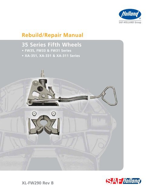
<strong>Rebuild</strong> Instructions3. Top Plate Removal1. Remove bracket pin retention bolts and nuts from bothsides of fifth wheel top plate (Figure 3).2. Using a pry bar, pull bracket retention pins out of fifthwheel top plate (Figure 3).3. Using a lifting device capable of lifting 500 lbs., removetop plate from mounting base. Place fifth wheel upsidedown on a flat, clean working area.Figure 3TOP PLATERETENTIONBOLTNOTE:Some fifth wheel assemblies have replaceablepocket inserts installed between fifth wheeltop plate and mounting base. Take care whenremoving the fifth wheel top plate not to losepocket inserts.4. Completely remove all components from the fifth wheeland discard.BRACKET PINPRY BARRETENTIONNUTIMPORTANT:IMPORTANT:NOTE:Your rebuild kit contains all componentsnecessary to completely rebuild your fifthwheel top plate. DO NOT reuse old parts.DO NOT remove the pocket inserts unlessthey are cracked or worn. Refer to Section11 for inspection information.Lock pins may be difficult to dislodge and mayrequire force to remove.Do not hit steel parts with a steel hammeras parts could break, sending flying steelfragments in any direction creating ahazard which, if not avoided, may resultin minor to moderate injury.5. Thoroughly steam clean top plate.6. Inspect fifth wheel top plate for cracks and for loose lockpins. Fifth wheels with cracks or loose lock pins holesmust be replaced.Failure to replace fifth wheels with cracksor loose lock pin holes may result intractor trailer separation which, if notavoided, could result in death or seriousinjury.Figure 4LOCK JAWSLOCK PIN HOLES10XL-FW290 Rev B · 02-10 · Amendments and errors reserved · © SAF-HOLLAND, Inc.
<strong>Rebuild</strong> Instructions4. Lock Installation1. Lubricate lock pin holes of lock jaws with Never-Seez(provided in kit.) (Figure 4).NOTE:Lubrication is not necessary for the XA-311NoLube installation.Figure 5KINGPIN GUIDEFACING BOTTOMSIDE OF FIFTHWHEELIMPORTANT:Only use Never-Seez when lubricatinglock pin holes of lock jaws. Do not use asubstitute lubricant.LOCK PINHOLES2. With the fifth wheel top plate upside down, align lock pinhole of lock jaws with lock pin holes in casting. Be certainto position lock jaws with kingpin guides facing bottomside of fifth wheel (Figure 5).3. With lock jaws properly positioned in the fifth wheelcasting, drive lock pins into lock jaws and casting holesuntil heads are flush with casting (Figure 6).4. Install retaining rings on lock pins (Figure 6).5. Insert a 2" diameter precision plug or the <strong>Holland</strong> LockGauge (Part No. TF-TLN-0237) into the lock jaws(Figure 7).Figure 6RETAINING RINGLOCK JAWSNOTE:You must use a <strong>Holland</strong> lock gauge (TF-0237)or a precision plug that is 2.000 +/- .005" forproper installation of the locking mechanism.CASTING HOLELOCK PINLOCK JAWSFigure 7HOLLAND LOCKGAUGE2.00"LOCK JAWSXL-FW290 Rev B · 02-10 · Amendments and errors reserved · © SAF-HOLLAND, Inc. 11
<strong>Rebuild</strong> Instructions6. Yoke Installation1. Lubricate tips of the yoke with a water-resistant lithiumbase grease (Figure 8).NOTE:Lubrication is not necessary for the XA-311NoLube installation.2. With the threaded hole facing up, slide yoke (Item 11)into the casting. Tap lightly to seat yoke around lock jaws(Figure 8).3. Inspect the amount of yoke tip engagement. The yoke tipsmust be flush with the end of the lock jaw or extend lessthan 1/2" beyond the lock jaw (Figure 9).Figure 8YOKETHREADED HOLEFACING UPLUBRICATEYOKE TIPNOTE:If the new yoke extends more than 1/2" beyondthe lock jaw DO NOT USE. Discard it andorder <strong>Holland</strong> part number XA-07295-THK.4. Install lock spring onto lock jaws (Figure 10).Figure 9YOKELOCK JAW1/2" MAX.Figure 10LOCK SPRINGLOCK JAWS12XL-FW290 Rev B · 02-10 · Amendments and errors reserved · © SAF-HOLLAND, Inc.
<strong>Rebuild</strong> Instructions5. Install yoke spring (Figure 11).6. Slide yoke shaft into casting, through the spring and intothe yoke. Align recessed hole in the shaft with threadedhole in the yoke (Figure 11).7. Slide lock adjustment tag, rubber washer and 13/16"washer onto yoke shaft (Figure 11).8. Insert a lock nut on the end of the yoke shaft and turn byhand until tight (Figure 11).7. Release Handle Installation1. Slide release handle (Item 23) through hole in side of fifthwheel top plate (Figure 12).LEFT-HAND RELEASE – Use Hole ARIGHT-HAND RELEASE – Use Hole BFigure 11LOCK NUT13/16" WASHERRUBBER WASHERLOCK ADJUSTMENTTAGYOKE SHAFTYOKE SPRINGYOKEFigure 12RIGHT-HANDRELEASE HANDLEHOLE BHOLE ABRACKETVERSIONCASTVERSIONLEFT-HANDRELEASEHANDLEXL-FW290 Rev B · 02-10 · Amendments and errors reserved · © SAF-HOLLAND, Inc. 13
<strong>Rebuild</strong> Instructions2. Slide 9/16" washer, handle spring and 17/32" washerin order over the “S” bend of the release handle(Figure 13).3. Compress spring using the 17/32" washer until cotter pinhole is exposed (Figure 13).4. Insert cotter pin into hole on the release handle, spreadcotter pin and wrap it completely around release handle(Figure 13).8. Cam Plate Installation1. Inspect cam plate for burrs. Service as necessary.2. Lubricate cam plate track and pivot hole with a waterresistant lithium base grease (Figure 14).Figure 13RELEASEHANDLEHANDLESPRINGCOTTERPIN17/32"WASHER 9/16"WASHERCOTTER PINWRAPPED AROUNDRELEASE HANDLECOTTERPIN HOLENOTE:Lubrication is not necessary for the XA-311NoLube installation.3. Install cam plate onto handle "S" bend (Figure 14).4. Position cam plate over fifth wheel top plate so that camplate attachment hole lines up with the proper casting lughole (Figure 15).5. Place a 9/16" washer between cam plate and casting lughole with rounded side of the washer facing cam plate(Figure 15).NOTE:When installing washer rounded edge of thewasher must always face cam plate.Figure 14RELEASE HANDLEATTACHMENT HOLECAM PLATECAM PLATE TRACKCASTING LUG HOLEFigure 15CAM PLATE9/16"WASHERROUNDED CORNERSFACING CAM PLATE14XL-FW290 Rev B · 02-10 · Amendments and errors reserved · © SAF-HOLLAND, Inc.
<strong>Rebuild</strong> Instructions6. Install 1/2" roller into cam plate and place a second9/16" washer on top of roller with rounded side facingcam plate (Figure 16).7. Install 1/2" bolt (Item 15) through washers, roller and topplate lug (Figure 16).8. Secure bolt with a 1/2" lock nut and tighten securely.Check for free movement of cam plate (Figure 16).9. Align cam plate track over the threaded hole in the yoke(Figure 16).10. Place a 21/32 ID x 2-5/8" OD washer between the yokeand cam plate with rounded side of washer facing camplate (Figure 17).11. Place a 5/8" roller into cam plate track, then place asecond 21/32 ID x 2-5/8" OD washer over roller withthe rounded side of washer facing the cam plate(Figure 17).12. Check alignment of the recessed hole in yoke shaft.13. Install 5/8" bolt through washers, roller, cam plate,washer and into threaded hole in the yoke (Figure 17).14. Tighten bolt securely, then check for free movement ofcam plate.Figure 161/2" BOLT1/2" ROLLERCAM PLATETRACK1/2" NUT9/16" WASHERCAM PLATE1-3/4"WASHERROUNDED CORNERSFACING CAM PLATECAM PLATECAM PLATEATTACHMENT HOLEHOLE FOR RIGHTHAND RELEASEFigure 175/8" BOLT21/32" WASHERCAM PLATECAM PLATE5/8" ROLLERCAM PLATE TRACK21/32" WASHERYOKETHREADED HOLEIN YOKEXL-FW290 Rev B · 02-10 · Amendments and errors reserved · © SAF-HOLLAND, Inc. 15
<strong>Rebuild</strong> Instructions9. Secondary Lock Installation(Automatic Version)Figure 181. Start roll pin into hole in the top plate opposite thecam attachment bolt (Figure 18).2. Assemble secondary lock to the torsion spring(Figure 18).ROLL PIN3. Drive roll pin through spring and lock until flush withcasting (Figure 18).4. Check lock spring for tension and lock for free movement.10. Secondary Lock Installation(<strong>Manual</strong> Version)SECONDARYLOCKTORSIONSPRINGTAILS OFSPRING MUSTREST AGAINSTCASTING1. Pass “S” bend of manual secondary release handlethrough casting guide hole (Figure 19).For left-hand release, use guide hole C.For right-hand release, use guide hole D.2. Pass “S” bend of release handle through small hole inthe secondary lock (Figure 19).Figure 193. Start roll pin into hole in top plate opposite camattachment bolt (Figure 18).4. Assemble secondary lock to the torsion spring(Figure 18).34DC 345. Drive roll pin through spring and lock until flush withcasting (Figure 18).356. Check for proper spring tension and operation by pullingrelease handle and hooking it on casting, then unhookinghandle and allowing spring to snap it closed.RIGHT-HANDRELEASELEFT-HANDRELEASE16XL-FW290 Rev B · 02-10 · Amendments and errors reserved · © SAF-HOLLAND, Inc.
<strong>Rebuild</strong> Instructions11. Top Plate Installation1. Visually inspect both pocket inserts for excessive wear,chips, cracks or gouges. If any of these conditions arefound, the pocket insert(s) must be replaced (Figure 20).Refer to Page 6 for kit ordering information.2. If pocket inserts are dislodged from fifth wheel casting,clean pocket area of casting and apply a strip of doubleface tape in bottom of pockets. Install pocket inserts bypressing them down into the pocket areas (Figure 22).3. Using a lifting device capable of lifting 500 lbs., installfifth wheel top plate onto its mounting base.4. Install bracket pins through fifth wheel casting andmounting base and secure by installing the bracket pinsretention bolts and nuts (Figure 22). Torque retentionfasteners to manufacturer recommendation.Figure 20POCKET INSERTFigure 21POCKETINSERTPOCKETAREAFigure 22TOPPLATERETENTIONBOLTRETENTIONNUTBRACKETPINXL-FW290 Rev B · 02-10 · Amendments and errors reserved · © SAF-HOLLAND, Inc.17
<strong>Rebuild</strong> Instructions5. To unlock fifth wheel, push down and rotate “J” hookso that it locks under front skirt of fifth wheel top plate(Figure 25).6. Pull release handle.7. Rotate handle on lock tester counter clockwise(Figure 26).8. Repeat coupling and uncoupling process with lock testera minimum of 2 times to help “seat” yoke. Then recheckadjustment of fifth wheel.9. With the fifth wheel unlocked, unhook “J” hook fromunder front skirt of fifth wheel top plate (Figure 27)and remove lock tester from fifth wheel.Figure 25“J” HOOKFRONT SKIRTOF TOP PLATEIMPORTANT:Before using your fifth wheel, visuallyinspect all components of fifth wheelfor proper operation while coupling anduncoupling fifth wheel with lock tester.Failure to repair an improperly operatingfifth wheel may result in tractor trailerseparation which, if not avoided, couldresult in serious injury or deathFigure 26IMPORTANT:Be sure to read and understand FifthWheel Operation Instructions published inXL-FW10009OM-en-US prior to use.Failure to read and understand FifthWheel Operation Instructions prior to usecan result in improper operation of fifthwheel which, if not avoided, could resultin death or serious injury.Figure 27“J” HOOKFRONT SKIRTOF TOP PLATEXL-FW290 Rev B · 02-10 · Amendments and errors reserved · © SAF-HOLLAND, Inc.19
From fifth wheel rebuild kits to suspension bushing repair kits,SAF-HOLLAND Original Parts are the same quality components used inthe original component assembly.SAF-HOLLAND Original Parts are tested and designed to providemaximum performance and durability. Will-fits, look-alikes or, worseyet, counterfeit parts will only limit the performance potential andcould possibly void SAF-HOLLAND’s warranty. Always be sure to specSAF-HOLLAND Original Parts when servicing yourSAF-HOLLAND product.SAF-HOLLAND USA · 888.396.6501 · Fax 800.356.3929www.safholland.usSAF-HOLLAND CANADA · 519.537.3494 · Fax 800.565.7753WESTERN CANADA · 604.574.7491 · Fax 604.574.0244www.safholland.caSAF-HOLLAND MEXICO · 52.1.55.545668641 · Fax 52.55.58162230www.safholland.com.mxinfo@safholland.comXLFW290 Rev B · 2010-02-15 · Amendments and Errors Reserved · © SAF-HOLLAND, Inc.SAF-HOLLAND USA, INC.1950 Industrial Blvd, Muskegon, MI 49443www.safholland.com