Pilot Operated 2-Port Solenoid Valve/ Zero ... - SMC Pneumatics
Pilot Operated 2-Port Solenoid Valve/ Zero ... - SMC Pneumatics
Pilot Operated 2-Port Solenoid Valve/ Zero ... - SMC Pneumatics
- No tags were found...

Create successful ePaper yourself
Turn your PDF publications into a flip-book with our unique Google optimized e-Paper software.
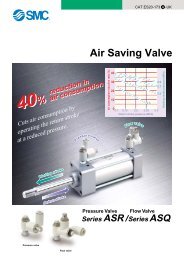
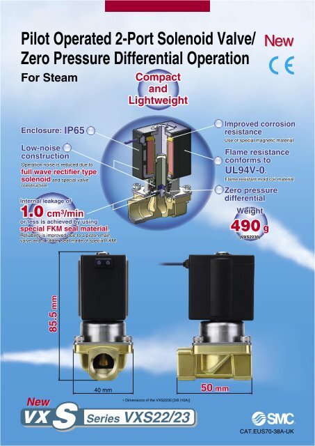
<strong>Pilot</strong> <strong>Operated</strong> 2-<strong>Port</strong> <strong>Solenoid</strong> <strong>Valve</strong>/<strong>Zero</strong> Pressure Differential OperationFor SteamCompactandLightweightNewEnclosure: IP65Low-noiseconstructionOperation noise is reduced due tofull wave rectifier typesolenoid and special valveconstruction.Internal leakage of1.0 cm 3 /minor less is achieved by usingspecial FKM seal material.Reliability is improved due to a piston mainvalve and a rubber seal made of special FKM.Improved corrosionresistanceUse of special magnetic materialFlame resistanceconforms toUL94V-0.Flame resistant mold coil material<strong>Zero</strong> pressuredifferentialWeight490 g(VXS2230)85.5 mmNewVX SSSeries40 mm 50 mm∗ Dimensions of the VXS2230 [3/8 (10A)]VXS22/23CAT.EUS70-38A-UK
<strong>Solenoid</strong> valves for various fluids used in a wide variety of<strong>Pilot</strong> operated 2-port solenoid valve for steam / <strong>Zero</strong> pressure differential operationFor SteamNew Series VXS22/23Normally closed operationNormally open operation78 8664 433Working principlesWhen the coil is energised, the armature assembly 6 is attracted to the core of the tubeassembly 7 and the pilot valve is opened.When the pilot valve is open the pressure inside the pilot chamber decreases, resultingin the pressure difference from the inlet pressure. Then the piston assembly 3 is lifted andthe main valve is opened.The armature assembly 6 interacts with the piston assembly 3 at location . The pistonassembly is pulled upward when the armature assembly is attracted to open the main valve .8 8Working principlesWhen the coil is de-energised, the armature assembly6 returns by the reacting force of the return spring 4 .When the pressure inside the pilot chamber increases,the pressure difference from the inlet pressure is lost andthe main valve is closed.Normally Closed (N.C.)<strong>Solenoid</strong> valve (<strong>Port</strong> size)Model<strong>Port</strong>symbol(<strong>Port</strong> size)VXS22 VXS2302 (1/4)03 (3/8)04 (1/2)06 (3/4)10 (1)3(10 mmø)Orifice symbol (diameter)4(15 mmø)5(20 mmø)6(25 mmø)MaterialBodyBrass (C37),StainlesssteelSealFKMApplicationsFor various industries which use steamSteam cooker Dish/container steriliser Steam pressSteam dryer Boiler Steam heaterFeatures 1
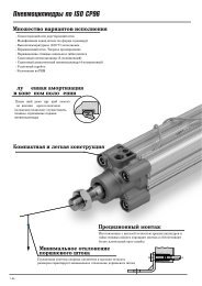
applications —<strong>Pilot</strong> operated 2-port<strong>Zero</strong> pressure differential operationFor Air, Water, OilNew VX SeriesNew VXZ22/23variationsDirect operated 2-portNewVX21/22/23For Air, Vacuum, Water, Steam, Oil<strong>Valve</strong> type<strong>Port</strong> sizeOrifice dia.mmø<strong>Valve</strong> type<strong>Port</strong> sizeOrifice dia.mmøN.C./N.O.1/4 to 110 to 25N.C./N.O.1/8 to 1/22 to 10<strong>Pilot</strong> operated 2-portNewVXD21/22/23For Water, Oil, AirDirect operated 3-portNewVX31/32/33For Air, Vacuum, Water, Steam, Oil<strong>Pilot</strong> operated 2-portVXP21/22/23For Steam (Air, Water, Oil)<strong>Valve</strong> typeN.C./N.O.<strong>Port</strong> size1/4 to 132A to 50AWater hammer relief,<strong>Pilot</strong> operated 2-portVXR21/22/23For Water, OilOrifice dia.mmø10 to 50<strong>Valve</strong> typeN.C./N.O.COM.<strong>Port</strong> size1/8 to 3/8Orifice dia.mmø1.5 to 4<strong>Pilot</strong> operated 2-port forhigh pressureVXH22For Air, Water, Oil<strong>Valve</strong> typeN.C./N.O.<strong>Port</strong> size1 1 / 4 to 232A to 50AOrifice dia.mmø35 to 502-port for dust collector(<strong>Solenoid</strong> type/Air operated type)VXF21/22, VXFA21/22For Air<strong>Valve</strong> typeN.C./N.O.<strong>Port</strong> size1/2 to 2Orifice dia.mmø20 to 50<strong>Valve</strong> typeN.C.<strong>Port</strong> size1/4 to 1/2Orifice dia.mmø10<strong>Valve</strong> typeN.C.<strong>Port</strong> size Orifice dia.mmø3/4 to 1 1 / 2 20 to 40The new VX series, with its improved construction, replaces our previous VX range.Features 2
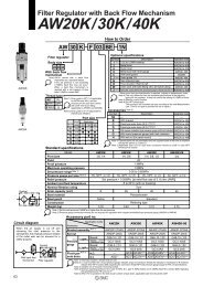
(DC spec.)CAT.ES70-31A<strong>Pilot</strong> <strong>Operated</strong> 2-<strong>Port</strong> <strong>Solenoid</strong> <strong>Valve</strong> for Steam<strong>Zero</strong> Pressure Differential OperationSeries VXS22/23For Steam <strong>Valve</strong>Normally closed (N.C.) <strong>Solenoid</strong> CoilCoil: Class H Rated Voltage100 VAC, 200 VAC, 110 VAC,220 VAC, 240 VAC, 230 VAC, 48 VAC MaterialBody Brass (C37), Stainless steelSeal FKM Electrical Entry• Grommet• Conduit• Conduit terminalModel VXS2230 VXS2240 VXS2350 VXS236010 mmø15 mmø20 mmø25 mmø<strong>Port</strong> size 1/4 (8A)(Nominal size) 3/8 (10A)1/2 (15A) 3/4 (20A) 1 (25A)Orifice dia.The VXZ series is recommended for air, water or oil.<strong>Pilot</strong> <strong>Operated</strong> 2-<strong>Port</strong> <strong>Solenoid</strong> <strong>Valve</strong><strong>Zero</strong> Pressure Differential OperationFor Air, Water, OilSeries VXZ22/231Normally Closed (N.C.) / Normally Open (N.O.)<strong>Solenoid</strong> valve (<strong>Port</strong> size)Model<strong>Port</strong>symbol(<strong>Port</strong> size)VXZ2202 (1/4)03 (3/8)04 (1/2)VXZ2306 (3/4)10 (1)3(10 mmø)Orifice symbol (diameter)4(15 mmø)5(20 mmø)6(25 mmø)BodyMaterialBrass (C37),StainlesssteelSealNBRFKMEPDM<strong>Zero</strong> Differential Pressure Type<strong>Pilot</strong> <strong>Operated</strong>2 <strong>Port</strong> <strong>Solenoid</strong> <strong>Valve</strong>For Air, Water, OilReducedpower consumptionVXZ22: 8 W → 7 WVXZ23: 11.5 W → 10.5 WNewVX Series Z VXZ22/23ZCAT.EUS70-31A-UK
Common SpecificationsStandard Specifications<strong>Valve</strong>specifications<strong>Valve</strong> constructionWithstand pressure (MPa) (Water pressure)Body materialSeal materialEnclosureEnvironmentRated voltage<strong>Pilot</strong> operated 2-port piston type/<strong>Zero</strong> pressure differential operation3.0Brass (C37), Stainless steelFKMDusttight, Water-jet-proof (IP65)Location without corrosive or explosive gases100 VAC, 200 VAC, 110 VAC, 220 VAC, 230 VAC, 240 VAC, 48 VACSpecificationsFor SteamCoilspecificationsAllowable voltage rangeAllowable leakage voltageCoil insulation type±10% of rated voltage10% or less of rated voltageClass H (Full wave rectifier type)Construction<strong>Solenoid</strong> Coil SpecificationsAC Specification (Class H coil, Full wave rectifier type)ModelVXS22VXS23Apparent power (VA) Note 2)1820Temperature rise (°C)120120Note 1)Note 1) The value at an ambient temperature of 20°C and when the rated voltage is applied.Note 2) There is no difference in the frequency and the inrush and energised apparentpower, since a rectifying circuit is used.Apparent power when the solenoid temperature is 20°C.DimensionsApplicable Fluid Check List / All OptionsVXS2 0SOption symbolR1Fluid and applicationOptionsymbolSealmaterialBody materialGuide ring andpiston ring materialSBrass (C37)Steam (1 MPa or less)FKMPPSQStainless steel∗ Use VXZ series when a fluid other than steam (air, water, oil) is used. (Refer to page 1 for details.)Coil insulationtypeH2
Series VXS22/23For Steam(1 MPa, 183°C or less)Model/<strong>Valve</strong> SpecificationsN.C.Passage symbol21Normally Closed (N.C.)<strong>Port</strong> size(Nominal size)1/4 (8A)3/8 (10A)1/2 (15A)3/4 (20A)Orificediameter(mmø)101520ModelVXS2230-02VXS2230-03VXS2240-04VXS2350-06Min. operatingpressuredifferential (MPa)0Max. operatingpressuredifferential (MPa)1 (25A) 25 VXS2360-10290 12.0Note) Weight of grommet type. Add 10 g for conduit type, 60 g for conduit terminal type respectively.• Refer to “Glossary of Terms” on page 12 for details on the maximum operating pressure differential and the maximum system pressure.1.0Flow-rate characteristicsAv x 10 –6 m 2 Conversion Cv582.4672.81305.32209.2Max. systempressure(MPa)1.0Weight (g)49066012001340Ambient and Fluid Temperature<strong>Valve</strong> Leakage RateInternal LeakagePower supplyAC, Class H coilFluid temperature (°C)<strong>Solenoid</strong> valve option symbolS, QSteam, 183 or lessAmbienttemperature(°C)–10 to 60Seal materialFKMLeakage rate (Air)1.0 cm 3 /min or lessNote) Dew point temperature: –10°C or lessRefer to page 9 for selection.3
<strong>Pilot</strong> <strong>Operated</strong> 2-<strong>Port</strong> <strong>Solenoid</strong> <strong>Valve</strong> for Steam<strong>Zero</strong> Pressure Differential Operation Series VXS22/23For SteamHow to OrderAC, Class H coilVXS 22 3 0(Full wave rectifier type)ModelRefer to the table below (1)for availability.SymbolSQOrifice diameterRefer to the below table (1)for availability.<strong>Valve</strong>/Body configuration0 N.C./Single unitSealmaterialFKM—ZOption—Oil-free spec.S<strong>Solenoid</strong> valve optionBody materialCoilinsulation typeBrass (C37)Stainless steelH<strong>Port</strong> sizeRefer to the table below (1)for availability.Thread type—TFN02 1 G R1RcNPTFGNPTFull waverectifier typeBracket— NoneB: With bracket∗ Bracket is not removable.Dimensions Construction For SteamSpecificationsRated voltage123100 VAC 50/60 Hz200 VAC 50/60 Hz110 VAC 50/60 Hz78J240 VAC 50/60 Hz48 VAC 50/60 Hz230 VAC 50/60 Hz4 220 VAC 50/60 Hz∗ Refer to the table below (2) for availability.Refer to page 7 for ordering coil only.Electrical entryG: Grommet C: Conduit T: With conduit terminalTL: With conduit terminaland light∗ Refer to the table (2) for the available combinations between electrical option (L) and rated voltage.∗ Surge voltage suppressor is integrated as standard into the full wave rectifier type.Table (1) Model – Orifice Diameter – <strong>Port</strong> SizeNormally Closed (N.C.)<strong>Solenoid</strong> valve (<strong>Port</strong> size)Orifice symbol (diameter)3 4 5 6Model VXS22 VXS23(10 mmø) (15 mmø) (20 mmø) (25 mmø)<strong>Port</strong>symbol(<strong>Port</strong> size)02 (1/4)03 (3/8)04 (1/2)06 (3/4)10 (1)Table (2) Rated Voltage – Electrical OptionRated voltageNote)LSpecificationsVoltagesymbolVoltageWith light1 100 V2 200 V3 110 VAC 4 220 V7 240 V8 48 VJ 230 VNote) Light is available only for conduit terminal type.4
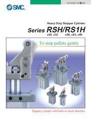
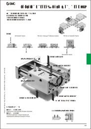
Series VXS22/23For SteamConstructionNormally closed (N.C.)Body material: Brass (C37), Stainless steel!0!1iuyrwotqeWorking principlesWhen the coil i is energised, the armature assembly y is attracted to the core of the tube assembly u and the pilot valveis opened.When the pilot valve is open the pressure inside the pilot chamber decreases, resulting in the pressure difference from theinlet pressure. Then, the piston assembly e is lifted and the main valve is opened.The armature assembly y interacts with the piston assembly e at location . The piston assembly is pulled upward when thearmature assembly is attracted to open the main valve .When the coil i is de-energised, the armature assembly y returns by the reacting force of the return spring r and the pilotvalve is closed.When the pilot valve is closed, the pressure inside the pilot chamber increases, resulting that the pressure difference fromthe inlet pressure is lost and the main valve is closed.Component PartsMaterialNo. DescriptionBody material Body material stainlessBrass (C37) specifications steel specifications1 BodyBrass (C37) Stainless steel234567891011BonnetPiston assemblyReturn springO-ringArmature assemblyTube assembly<strong>Solenoid</strong> coilHexagon socket head boltName plateClipStainless steelPPS, Stainless steel (PTFE, FKM)Stainless steelFKMStainless steel, PPSStainless steel—Stainless steelALSKThe materials in parentheses are the seal materials.5
<strong>Pilot</strong> <strong>Operated</strong> 2-<strong>Port</strong> <strong>Solenoid</strong> <strong>Valve</strong> for Steam<strong>Zero</strong> Pressure Differential Operation Series VXS22/23For SteamDimensions/Body Material: Brass (C37), Stainless SteelVXS220/VXS230Grommet: GConduit: CSpecifications300 M E39.4 120aCe300 M39.4 100For SteamLBLAF(D)bHNL25 32ghfdINOUTJKiINOUT10.5DimensionsConstructionConduit terminal: T34INOUTRModelN.C.VXS2230VXS2240VXS2350VXS2360<strong>Port</strong> sizeP1/4, 3/81/23/41A B C D E F H J K85.592.510911511141821353540405063809022.522.52525303747.555202632.53522 4029.5 5236 6540.5 70(mm)Electrical entryGrommet Conduit Conduit terminalL M L M L N R77 22.5 71 43 71 106.5 74.584 22.5 78 43 78 106.5 74.5100.5 25.5 93 46 93 109 77106.5 25.5 99 46 99 109 77(mm)ModelN.C.VXS2230VXS2240VXS2350VXS2360<strong>Port</strong> sizeP1/4, 3/81/23/41a b d e f g h i5260687367758792141722221.62.32.62.622.528.537405.56.56.56.57.58.59928354345Weight(g)490660120013406
Series VXS22/23For SteamReplacement Parts <strong>Solenoid</strong> coil assembly part numberAC, Class H coil (DIN terminal is not available.)VX022 N 1 GRH23SeriesVXS22VXS23Coil insulation typeSymbolHTypeClass HWith full wave rectifierElectrical entryG: Grommet C: Conduit T: With conduit terminalTL: With conduit terminaland light∗ Refer to the table (1) for the available combinations between electrical option (L) and rated voltage.∗ The rectifier and the surge voltage suppressor are integrated as standard.Rated voltage Note)1 100 VAC 50/60 Hz2 200 VAC 50/60 Hz3 110 VAC 50/60 Hz4 220 VAC 50/60 Hz7 240 VAC 50/60 Hz8 48 VAC 50/60 HzJ 230 VAC 50/60 HzNote) Refer to the table (1) for theavailable combinations.Table (1) Rated Voltage – Electrical OptionSpecificationsACRated voltageVoltagesymbol123478JVoltage100 V200 V110 V220 V240 V48 V230 VClass HLNote)With lightNote) Light is available only for conduit terminal type.7
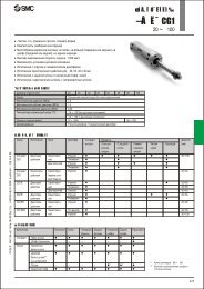
<strong>Solenoid</strong> <strong>Valve</strong>Flow-rate Characteristics(How to indicate flow-rate characteristics)1. Indication of Flow-rate CharacteristicsThe flow-rate characteristics in equipment such as a solenoid valve, etc. are indicated in their specificationsshown in Table (1).Table (1) Indication of Flow-rate CharacteristicsCorrespondingequipmentProcess fluidcontrolequipmentPneumaticequipmentIndication byinternational standardAv—C, b—Otherindications—Cv—SCvISO 6358: 1989JIS B 8390: 2000Conformed standardsIEC60534-2-3: 1997JIS B 2005: 1995Equipment: JIS B 8471, 8472, 8473JIS B 8390: 2000Equipment: JIS B 8373, 8374, 8375, 8379, 8381ANSI/(NFPA)T3.21.3: 19902. Flow-rate CharacteristicsNote) Use this chart as a guide. In the case of finding an accurate flow rate, refer to pages 9 to 11.For Saturated SteamDownstream pressure of valve (P2) MPa1.00.90.80.70.60.50.40.30.20.1[663] (183)[664] (179)[662] (174)[661] (170)[660] (164)[658] (158)[656] (151)[654] (143)[650] (133)[646] (120)0.950.90.850.80.750.70.650.60.550.50.450.40.350.30.250.20.150.10.05Upstream pressure of valve P1 Approx.1.0 MPaSubsonicCriticalpressureSonicVXS2230-02VXS2230-03VXS2240-04VXS2350-06VXS2360-1050 100 15050 100 150 200 250100200300400500600200 400 600 800 1000200 400 600 800 1000 1200 1400Flow rate Q kg/h200ø10ø10ø15ø20ø25Figures inside [ ] indicate the saturated steam holding heat (kcal/kg). Figures inside ( ) indicate the saturation temperature (°C).How to read the chartThe sonic range pressure to generate a flow rate of 400 kg/h is P1 Approx. 0.64 MPa for ø15 orifice (VXS224-04).The holding heat slightly differs depending on the pressure P1, but at 400 kg/h it is approx. 25900 kcal/h.9
<strong>Solenoid</strong> <strong>Valve</strong> Flow-rate Characteristics3. Process Fluid Control Equipment(1) Conformed standardIEC60534-2-3: 1997: Industrial process control valves. Part 2: Flow capacity, Section Three-TestproceduresJIS B 2005: 1995: Test method for the flow coefficient of a valveEquipment standards: JIS B 8471: <strong>Solenoid</strong> valve for waterJIS B 8472: <strong>Solenoid</strong> valve for steamJIS B 8473: <strong>Solenoid</strong> valve for fuel oil(2) Definition of flow-rate characteristicsAv factor: Value of the clean water flow rate represented by m 3 /s which runs through a valve (equipment fortest) when the pressure differential is 1 Pa. It is calculated using the following formula.ρAv = Q —— ································································································ (1)∆PAv : Flow coefficient [m 2 ]Q : Flow rate [m 3 /s]∆P : Pressure differential [Pa]ρ : Density of fluid [kg/m 3 ](3) Formula of flow rateIt is described by the practical units. Also, the flow-rate characteristics are shown in Chart (1).For saturated steam:P1 – 0.1Critical pressure = ————2WhenP1 – 0.1P2 > ————, subsonic flow2Q = 8.3 x 10 6 Av ∆P (P2 + 0.1) ···································································· (2)WhenP1 – 0.1P2 < ————, sonic flow2(P1 – 0.1)Q = 8.3 x 10 26 Av ————— + 0.1 x P1 ······················································ (3)4Q : Flow rate [l/min]Av : Flow coefficient [m 2 ]∆P : Pressure differential [MPa]P1 : Upstream pressure [MPa]: ∆P = P1 – P2P2 : Downstream pressure [MPa]Conversion of flow coefficient:Av = 28 x 10 –6 Kv = 24 x 10 –6 Cv ·································································· (4)Here,Kv factor: Value of the clean water flow rate represented by m 3 /h which runs through avalve at 5 to 40°C, when the pressure differential is 1 bar.Cv factor (Reference values) : Figures representing the flow rate of clean water by US gal/min whichrunsthrough a valve at 60°F, when the pressure differential is 1 lbf/in 2 (psi).Value is different from Kv and Cv factors for pneumatic purpose due to different test method.10
<strong>Solenoid</strong> <strong>Valve</strong> Flow-rate Characteristics3Water flow rate Q0 [l /min] (when Av = 1 x 10 –6 [m 2 ])210.90.80.70.60.50.40.30.2Upstream pressureP1 = 1 MPaP1 = 0.8 MPaP1 = 0.6 MPaP1 = 0.5 MPaP1 = 0.4 MPaP1 = 0.3 MPa Example 1P1 = 0.2 MPaP1 = 0.1 MPa0.10.0010.002 0.003 0.0040.01 0.02 0.03 0.040.1Example 1)Find the pressure differential when water 15 [l/min] runs through a solenoid valve with an Av = 45 x 10 –6 [m 2 ].Since Q0 = 15/45 = 0.33 [l/min], according to Chart (1), if reading ∆P when Q0 is 0.33, it will be 0.031 [MPa].(4) Test methodAttach a test equipment to the test circuit shown in Fig. (2). Next, pour water at 5 to 40°C, then measure theflow rate with a pressure differential of 0.075 MPa. However, the pressure differential needs to be set with alarge enough difference so that the Reynolds number does not go below a range of 4 x 10 4 .By substituting the measurement results in formula (1) is figured out Av.ThermometerRestrictorin theupstream sideFlowmeterPressuretap2d≥ 20dTest rangeEquipmentfor testChart (1) Flow-rate characteristicsPressuretap≥ 10dRestrictorin thedownstreamsideFig. (2) Test circuit based on IEC60534-2-3, JIS B 20056dPressure differential ∆P [MPa]Vapour Dome (Water)Pressure [MPa]2.01.81.61.41.21.00.80.60.40.20.0100 110120130140150Temperature [°C]The chart above is calculated using the Antoine equation.16017018019020021022011
Glossary of TermsPressure Terminology1. Maximum operating pressure differentialThe maximum pressure differential (the difference betweenthe inlet and outlet pressure) which is allowed for operation,with the valve closed or open. When the outlet pressure is0 MPa, this becomes the maximum operating pressure.2. Minimum operating pressure differentialThe minimum pressure differential (the difference between theinlet pressure and outlet pressure) required to keep the mainvalve stably operated.3. Maximum system pressureThe maximum pressure that can be applied inside the pipelines.(Line pressure) [The pressure differential of the solenoid valveportion must be less than the maximum operating pressure differential.]Others1. MaterialNBR: Nitrile rubberFKM: Fluoro rubber – Product name: Viton ® , Dai-el ® , etc.EPDM: Ethylene propylene rubber2. Oil-free treatmentThe degreasing and washing of wetted parts.3. Passage symbolIn the JIS symbol ( ) IN and OUT are in a blocked condition( ), but actually in the case of reverse pressure (OUT>IN), there is a limit to the blocking.( ) is used to indicate that blocking of reverse pressure is notpossible.4. Proof pressureThe pressure the valve must be withstand without a drop in performanceafter holding for 1 minute under the prescribed pressure(static pressure) and returning to the operating pressurerange. [Value under the prescribed conditions]Electrical Terminology1. Apparent power (VA)Volt-ampere is the product of voltage (V) and current (A). Powerconsumption (W): For AC, W = V·A·cosθ. For DC, W = V·A.Note) cosθ shows power factor. cosθ = 0.62. Surge voltageA high voltage which is momentarily generated by shutting offthe power in the shut-off area.3. EnclosureA degree of protection defined in the “JIS C 0920: Waterprooftest of electric machinery/appliance and the degree of protectionagainst the intrusion of solid foreign objects”.IP65: Dusttight, Water-jet-proof“Water-jet-proof” means that no water intrudes inside anequipment that could hinder from operating normally by meansof applying water for 3 minutes in the prescribed manner. Takeappropriate protection measures, since a device is not usable inan environment where a droplet of water is splashed.12
Safety InstructionsThese safety instructions are intended to prevent hazardous situations and/or equipment damage.These instructions indicate the level of potential hazard with the labels of “Caution,” “Warning” or“Danger.” They are all important notes for safety and must be followed in addition to InternationalStandards (ISO/IEC) Note 1) , and other safety regulations.Note 1) ISO 4414: Pneumatic fluid power – General rules relating to systems.ISO 4413: Hydraulic fluid power – General rules relating to systems.IEC 60204-1: Safety of machinery – Electrical equipment of machines. (Part 1: General requirements)ISO 10218-1: Manipulating industrial robots - Safety.etc.Caution:Warning:Danger :Caution indicates a hazard with a low level of risk which, if not avoided, could result in minor ormoderate injury.Warning indicates a hazard with a medium level of risk which, if not avoided, could result in death orserious injury.Danger indicates a hazard with a high level of risk which, if not avoided, will result in death or seriousinjury.Warning1. The compatibility of the product is the responsibility of the person who designs the equipmentor decides its specifications.Since the product specified here is used under various operating conditions, its compatibility with specific equipment mustbe decided by the person who designs the equipment or decides its specifications based on necessary analysis and testresults. The expected performance and safety assurance of the equipment will be the responsibility of the person whohas determined its compatibility with the product. This person should also continuously review all specifications of theproduct referring to its latest catalogue information, with a view to giving due consideration to any possibility of equipmentfailure when configuring the equipment.2. Only personnel with appropriate training should operate machinery and equipment.The product specified here may become unsafe if handled incorrectly. The assembly, operation and maintenance ofmachines or equipment including our products must be performed by an operator who is appropriately trained andexperienced.3. Do not service or attempt to remove product and machinery/equipment until safety is confirmed.1. The inspection and maintenance of machinery/equipment should only be performed after measures to prevent fallingor runaway of the driven objects have been confirmed.2. When the product is to be removed, confirm that the safety measures as mentioned above are implemented and thepower from any appropriate source is cut, and read and understand the specific product precautions of all relevantproducts carefully.3. Before machinery/equipment is restarted, take measures to prevent unexpected operation and malfunction.4. Contact <strong>SMC</strong> beforehand and take special consideration of safety measures if the product is tobe used in any of the following conditions.1. Conditions and environments outside of the given specifications, or use outdoors or in a place exposed to directsunlight.2. Installation on equipment in conjunction with atomic energy, railways, air navigation, space, shipping, vehicles, military,medical treatment, combustion and recreation, or equipment in contact with food and beverages, emergency stopcircuits, clutch and brake circuits in press applications, safety equipment or other applications unsuitable for thestandard specifications described in the product catalogue.3. An application which could have negative effects on people, property, or animals requiring special safety analysis.4. Use in an interlock circuit, which requires the provision of double interlock for possible failure by using a mechanicalprotective function, and periodical checks to confirm proper operation.Back page 1
Safety InstructionsCaution1. The product is provided for use in manufacturing industries.The product herein described is basically provided for peaceful use in manufacturing industries.If considering using the product in other industries, consult <strong>SMC</strong> beforehand and exchange specifications or a contractif necessary.If anything is unclear, contact your nearest sales branch.Limited warranty and Disclaimer/Compliance RequirementsThe product used is subject to the following “Limited warranty and Disclaimer” and “Compliance Requirements”.Read and accept them before using the product.Limited warranty and Disclaimer1. The warranty period of the product is 1 year in service or 1.5 years after the product is delivered. Note 2)Also, the product may have specified durability, running distance or replacement parts. Please consult your nearestsales branch.2. For any failure or damage reported within the warranty period which is clearly our responsibility, a replacement productor necessary parts will be provided.This limited warranty applies only to our product independently, and not to any other damage incurred due to the failureof the product.3. Prior to using <strong>SMC</strong> products, please read and understand the warranty terms and disclaimers noted in the specifiedcatalogue for the particular products.Note 2) Vacuum pads are excluded from this 1 year warranty.A vacuum pad is a consumable part, so it is warranted for a year after it is delivered.Also, even within the warranty period, the wear of a product due to the use of the vacuum pad or failure due to the deterioration ofrubber material are not covered by the limited warranty.Compliance Requirements1. The use of <strong>SMC</strong> products with production equipment for the manufacture of weapons of mass destruction (WMD) orany other weapon is strictly prohibited.2. The exports of <strong>SMC</strong> products or technology from one country to another are governed by the relevant security lawsand regulations of the countries involved in the transaction. Prior to the shipment of a <strong>SMC</strong> product to anothercountry, assure that all local rules governing that export are known and followed.Back page 2
Series VXSSpecific Product Precautions 1Be sure to read before handling.Refer to back pages 1 and 2 for Safety Instructions, “Handling Precautions for <strong>SMC</strong>Products” (M-E03-3) for 2 <strong>Port</strong> <strong>Solenoid</strong> <strong>Valve</strong>s for Fluid Control Precautions.WarningOperating Environment1. Do not use the valves in an atmosphere having corrosivegases, chemicals, sea water, water, watersteam, or where there is direct contact with any ofthese.2. Do not use in explosive atmospheres.3. Do not use in locations subject to vibration or impact.4. Do not use in locations where radiated heat will bereceived from nearby heat sources.5. Employ suitable protective measures in locationswhere there is contact with water droplets, oil orwelding spatter, etc.CautionWarningLubrication1. Do not apply lubricant to the solenoid valve.Scale and sludge are generated by the reaction of oil andsteam, and cause destruction and malfunction.Do not apply lubricant to the solenoid valve.Maintenance1. Removing the productThe valve will reach a high temperature when used with hightemperature fluids. Confirm that the valve temperature hasdropped sufficiently before performing work. If touched inadvertently,there is a danger of being burned.1. Shut off the fluid supply and release the fluid pressure inthe system.2. Shut off the power supply.3. Dismount the product.2. Low frequency operationSwitch valves at least once every 30 days to prevent malfunction.Also, in order to use it under the optimum state, conducta regular inspection once a half year.Caution1. LubricationDo not apply lubricant to the solenoid valve.Scale and sludge are generated by the reaction of oil andsteam, and cause destruction and malfunction.2. StorageIn case of long term storage after use with heated water, thoroughlyremove all moisture to prevent rust and deteriorationof rubber materials, etc.3. Depending on the water quality, the brass body maycorrode due to dezincification, causing internal leakage.Inspect the product once every six months. If any problem isfound, replace it with a product with a stainless steel body.WarningMaintenanceOperating Precautions1. <strong>Valve</strong>s will reach high temperatures from high temperaturefluids. Use caution, as there is a danger ofbeing burned if a valve is touched directly.2. Arrange piping so that condensate will not accumulatein the solenoid valve.Install the piping to the solenoid valve higher than peripheralpiping. Be sure to avoid installing the piping to the solenoidvalve at the lowest part of the piping layout. If condensate accumulatesin the solenoid valve or peripheral piping, thesteam entering the piping will cause steam hammer. This willlead to destruction and malfunction of the solenoid valve andpiping. If steam hammer causes problems, install by-pass pipingto thoroughly discharge condensate from the piping.Apply steam to the device afterwards to start operation.Caution1. The valve of the pilot-operated 2-port solenoid valvemay be opened momentarily and result in fluidleakage when pressure is applied to the valve suddenly(if the pump or supply valve starts, for example)while the valve is closed. Please be cautious ofthis.Back page 3
Series VXSSpecific Product Precautions 2Be sure to read before handling.Refer to back pages 1 and 2 for Safety Instructions, “Handling Precautions for <strong>SMC</strong>Products” (M-E03-3) for 2 <strong>Port</strong> <strong>Solenoid</strong> <strong>Valve</strong>s for Fluid Control Precautions.WarningDesign1. Cannot be used as an emergency shutoff valve, etc.The valves presented in this catalogue are not designed forsafety applications such as an emergency shutoff valve. If thevalves are used in this type of system, other reliable safety assurancemeasures should also be adopted.2. Extended periods of continuous energisationThe solenoid coil will generate heat when continuously energised.Avoid using in a tightly shut container. Install it in a wellventilatedarea. Furthermore, do not touch it while it is beingenergised or right after it is energised.3. This solenoid valve cannot be used for explosionproof applications.4. Maintenance spaceThe installation should allow sufficient space for maintenanceactivities.5. Actuator driveWhen an actuator, such as a cylinder, is to be driven using avalve, take appropriate measures to prevent potential dangercaused by actuator operation.6. Pressure (including vacuum) holdingIt is not usable for an application such as holding the pressure(including vacuum) inside of a pressure vessel because airleakage is entailed in a valve.7. When the conduit type is used as equivalent to anIP65 enclosure, install a wiring conduit, etc.8. When an impact, such as steam hammer, etc., causedby the rapid pressure fluctuation is applied, thesolenoid valve may be damaged. Give an attentionto it.WarningSelection1. Confirm the specifications.Give careful consideration to the operating conditions such asthe application, fluid and environment, and use within the operatingranges specified in this catalogue.2. Fluid1. Type of fluidThis product is applicable only for steam of 183°C/1 MPa orless.2. Flammable oil, gasDo not use with these fluids, as they can cause destructionor malfunction.3. Corrosive gasCannot be used since it will lead to cracks by stress corrosionor result in other incidents.4. Use an oil-free specification when any oily particle must notenter the passage.5. Applicable fluid on the list may not be used depending onthe operating condition. Give adequate confirmation, andthen determine a model, just because the compatibility listshows the general case.3. Steam qualityThe use of steam containing foreign matter can cause problemssuch as malfunction and seal failure by promoting wearof the valve seat and armature, and by sticking to the slidingparts of the armature, etc. Install a suitable filter (strainer) immediatelyupstream from the valve. As a general rule, use 80to 100 mesh.When used to supply water to boilers, substances such as calciumand magnesium which generate hard scale and sludgeare included. Since this scale and sludge can cause the valveto malfunction, install water softening equipment, and a filter(strainer) directly upstream from the valve to remove thesesubstances.Do not use steam which includes chemicals, synthetic oilscontaining organic solvents, salt or corrosive gases, etc., as itcan cause destruction or malfunction.4. Ambient environmentUse within the operable ambient temperature range. Confirmthe compatibility between the product’s composition materialsand the ambient atmosphere. Be sure that the fluid used doesnot touch the external surface of the product.Back page 4
Series VXSSpecific Product Precautions 3Be sure to read before handling.Refer to back pages 1 and 2 for Safety Instructions, “Handling Precautions for <strong>SMC</strong>Products” (M-E03-3) for 2 <strong>Port</strong> <strong>Solenoid</strong> <strong>Valve</strong>s for Fluid Control Precautions.Caution1. Leakage voltageParticularly when using a resistor in parallel with a switchingelement and using a C-R element (surge voltage suppressor)to protect the switching element, take note that leakage currentwill flow through the resistor, C-R element, etc., creatinga possible danger that the valve may not turn off.Power supply2. Low temperature operation1. The valve can be used in an ambient temperature of between–10 to –20°C. However, take measures to preventfreezing or solidification of impurities, etc.2. When using valves for water application in cold climates, takeappropriate countermeasures to prevent the water fromfreezing in tubing by draining the water, etc. When warmingby a heater, etc., be careful not to expose the coil portion toa heater. Installation of a dryer, heat retaining of the body isrecommended to prevent a freezing condition in which thedew point temperature is high and the ambient temperatureis low, and the high flow runs.WarningSelectionSwitching elementOFFCRLeakage current10% or less of rated voltageMountingLeakage voltage<strong>Valve</strong>1. If air leakage increases or equipment does not operateproperly, stop operation.After mounting is completed, confirm that it has been done correctlyby performing a suitable function test.2. Do not apply external force to the coil section.When tightening is performed, apply a wrench or other tool tothe outside of the piping connection parts.3. Be sure not to position the coil downwards.When mounting a valve with its coil positioned downwards, foreignobjects in the fluid will adhere to the iron core leading tomalfunction.4. Do not warm the coil assembly with a heat insulator,etc.Use tape, heaters, etc., for freeze prevention in the piping andbody only. They can cause the coil to burn out.5. Secure with brackets, except in the case of steel pipingand copper fittings.6. Avoid sources of vibration, or adjust the arm fromthe body to the minimum length so that resonancewill not occur.7. Painting and coatingWarnings or specifications printed or labeled on the productshould not be erased, removed or covered up.CautionPiping1. Preparation before pipingBefore piping is connected, it should be thoroughly blown outwith air (flushing) or washed to remove chips, cutting oil andother debris from inside the pipe.Install piping so that it does not apply pulling, pressing, bendingor other forces on the valve body.2. Wrapping of pipe tapeWhen connecting pipes, fittings,etc., be sure that chips from the pipethreads and sealing material donot enter the valve.Furthermore, when pipe tape isused, leave 1.5 to 2 thread ridgesexposed at the end of the threads.Tightening Torque for PipingConnection thread Proper tightening torque N ⋅ mRc1/412 to 14Rc3/822 to 24Rc1/228 to 30Rc3/428 to 30Rc136 to 38WindingdirectionExpose approx. 2 threads.Pipe tape3. If an excessive amount ofthread sealant such as seal tapeor liquid thread sealant is used during piping, itwill get inside the product and lead to malfunction.4. Always tighten threads with the proper tighteningtorque.When attaching fittings to valves, tighten with the proper tighteningtorque shown below.5. Connection of piping to productsWhen connecting piping to a product, refer to its instructionmanual to avoid mistakes regarding the supply port, etc.6. Steam generated in a boiler contains a largeamount of drainage. Be sure to operate it with adrain trap installed.7. Arrange piping so that condensate will not accumulatein the solenoid valve.Install the piping to the solenoid valve higher than peripheralpiping. Be sure to avoid installing the piping to the solenoidvalve at a lower part of the piping layout. If condensate accumulatesin the solenoid valve or peripheral piping, the steamentering the piping will cause steam hammer. This will lead todestruction and malfunction of the solenoid valve and piping. Ifsteam hammer causes problems, install by-pass piping to thoroughlydischarge condensate from the piping. Apply steam tothe device afterwards to start operation.8. If the effective area of piping on the fluid supply sideis restricted, the operating time may becomeunstable due to differential pressure fluctuationwhen the valve is closed.9. For the convenience of maintenance and repair, installa by-pass circuit and use a union for piping.10. To control the fluid in the tank, connect the piping alittle higher than the bottom of the tank.Back page 5
© DiskArt 1988EUROPEAN SUBSIDIARIES:Austria<strong>SMC</strong> Pneumatik GmbH (Austria).Girakstrasse 8, A-2100 KorneuburgPhone: +43 2262-622800, Fax: +43 2262-62285E-mail: office@smc.athttp://www.smc.atFrance<strong>SMC</strong> Pneumatique, S.A.1, Boulevard de Strasbourg, Parc Gustave EiffelBussy Saint Georges F-77607 Marne La Vallee Cedex 3Phone: +33 (0)1-6476 1000, Fax: +33 (0)1-6476 1010E-mail: contact@smc-france.frhttp://www.smc-france.frNetherlands<strong>SMC</strong> <strong>Pneumatics</strong> BVDe Ruyterkade 120, NL-1011 AB AmsterdamPhone: +31 (0)20-5318888, Fax: +31 (0)20-5318880E-mail: info@smcpneumatics.nlhttp://www.smcpneumatics.nlSpain<strong>SMC</strong> España, S.A.Zuazobidea 14, 01015 VitoriaPhone: +34 945-184 100, Fax: +34 945-184 124E-mail: post@smc.smces.eshttp://www.smc.euBelgium<strong>SMC</strong> <strong>Pneumatics</strong> N.V./S.A.Nijverheidsstraat 20, B-2160 WommelgemPhone: +32 (0)3-355-1464, Fax: +32 (0)3-355-1466E-mail: info@smcpneumatics.behttp://www.smcpneumatics.beGermany<strong>SMC</strong> Pneumatik GmbHBoschring 13-15, D-63329 EgelsbachPhone: +49 (0)6103-4020, Fax: +49 (0)6103-402139E-mail: info@smc-pneumatik.dehttp://www.smc-pneumatik.deNorway<strong>SMC</strong> <strong>Pneumatics</strong> Norway A/SVollsveien 13 C, Granfos Næringspark N-1366 LysakerTel: +47 67 12 90 20, Fax: +47 67 12 90 21E-mail: post@smc-norge.nohttp://www.smc-norge.noSweden<strong>SMC</strong> <strong>Pneumatics</strong> Sweden ABEkhagsvägen 29-31, S-141 71 HuddingePhone: +46 (0)8-603 12 00, Fax: +46 (0)8-603 12 90E-mail: post@smcpneumatics.sehttp://www.smc.nuBulgaria<strong>SMC</strong> Industrial Automation Bulgaria EOODBusiness Park Sofia, Building 8 - 6th floor, BG-1715 SofiaPhone:+359 2 9744492, Fax:+359 2 9744519E-mail: office@smc.bghttp://www.smc.bgGreece<strong>SMC</strong> Hellas EPEAnagenniseos 7-9 - P.C. 14342. N. Philadelphia, AthensPhone: +30-210-2717265, Fax: +30-210-2717766E-mail: sales@smchellas.grhttp://www.smchellas.grPoland<strong>SMC</strong> Industrial Automation Polska Sp.z.o.o.ul. Poloneza 89, PL-02-826 Warszawa,Phone: +48 22 211 9600, Fax: +48 22 211 9617E-mail: office@smc.plhttp://www.smc.plSwitzerland<strong>SMC</strong> Pneumatik AGDorfstrasse 7, CH-8484 WeisslingenPhone: +41 (0)52-396-3131, Fax: +41 (0)52-396-3191E-mail: info@smc.chhttp://www.smc.chCroatia<strong>SMC</strong> Industrijska automatika d.o.o.Crnomerec 12, HR-10000 ZAGREBPhone: +385 1 377 66 74, Fax: +385 1 377 66 74E-mail: office@smc.hrhttp://www.smc.hrHungary<strong>SMC</strong> Hungary Ipari Automatizálási Kft.Torbágy út 19, H-2045 TörökbálintPhone: +36 23 511 390, Fax: +36 23 511 391E-mail: office@smc.huhttp://www.smc.hu<strong>Port</strong>ugal<strong>SMC</strong> Sucursal <strong>Port</strong>ugal, S.A.Rua de Engº Ferreira Dias 452, 4100-246 <strong>Port</strong>oPhone: +351 226 166 570, Fax: +351 226 166 589E-mail: postpt@smc.smces.eshttp://www.smc.euTurkeyEntek Pnömatik San. ve Tic. A*.Perpa Ticaret Merkezi B Blok Kat:11 No: 1625, TR-34386, Okmeydani, IstanbulPhone: +90 (0)212-444-0762, Fax: +90 (0)212-221-1519E-mail: smc@entek.com.trhttp://www.entek.com.trCzech Republic<strong>SMC</strong> Industrial Automation CZ s.r.o.Hudcova 78a, CZ-61200 BrnoPhone: +420 5 414 24611, Fax: +420 5 412 18034E-mail: office@smc.czhttp://www.smc.czIreland<strong>SMC</strong> <strong>Pneumatics</strong> (Ireland) Ltd.2002 Citywest Business Campus, Naas Road, Saggart, Co. DublinPhone: +353 (0)1-403 9000, Fax: +353 (0)1-464-0500E-mail: sales@smcpneumatics.iehttp://www.smcpneumatics.ie© DiskArtRomaniaUK<strong>SMC</strong> Romania srl<strong>SMC</strong> <strong>Pneumatics</strong> (UK) LtdStr Frunzei 29, Sector 2, BucharestVincent Avenue, Crownhill, Milton Keynes, MK8 0ANPhone: +40 213205111, Fax: +40 213261489 Phone: +44 (0)845 121 5122 Fax: +44 (0)1908-555064E-mail: smcromania@smcromania.ro E-mail: sales@smcpneumatics.co.ukhttp://www.smcromania.rohttp://www.smcpneumatics.co.ukDenmark<strong>SMC</strong> Pneumatik A/SEgeskovvej 1, DK-8700 HorsensPhone: +45 70252900, Fax: +45 70252901E-mail: smc@smcdk.comhttp://www.smcdk.comItaly<strong>SMC</strong> Italia S.p.AVia Garibaldi 62, I-20061 Carugate, (Milano)Phone: +39 (0)2-92711, Fax: +39 (0)2-9271365E-mail: mailbox@smcitalia.ithttp://www.smcitalia.itRussia<strong>SMC</strong> Pneumatik LLC.4B Sverdlovskaja nab, St. Petersburg 195009Phone.:+7 812 718 5445, Fax:+7 812 718 5449E-mail: info@smc-pneumatik.ruhttp://www.smc-pneumatik.ruEstonia<strong>SMC</strong> <strong>Pneumatics</strong> Estonia OÜLaki 12, 106 21 TallinnPhone: +372 6510370, Fax: +372 65110371E-mail: smc@smcpneumatics.eehttp://www.smcpneumatics.eeLatvia<strong>SMC</strong> <strong>Pneumatics</strong> Latvia SIADzelzavas str. 120g, Riga LV-1021, LATVIAPhone: +371 67817700, Fax: +371 67817701E-mail: info@smclv.lvhttp://www.smclv.lvSlovakia<strong>SMC</strong> Priemyselná Automatizáciá, s.r.o.Fatranská 1223, 01301 Teplicka Nad VáhomPhone: +421 41 3213212 - 6 Fax: +421 41 3213210E-mail: office@smc.skhttp://www.smc.skFinland<strong>SMC</strong> <strong>Pneumatics</strong> Finland OyPL72, Tiistinniityntie 4, SF-02231 ESPOOPhone: +358 207 513513, Fax: +358 207 513595E-mail: smcfi@smc.fihttp://www.smc.fiLithuania<strong>SMC</strong> <strong>Pneumatics</strong> Lietuva, UABOslo g.1, LT-04123 VilniusPhone: +370 5 2308118, Fax: +370 5 2648126E-mail: info@smclt.lthttp://www.smclt.ltSlovenia<strong>SMC</strong> industrijska Avtomatika d.o.o.Mirnska cesta 7, SI-8210 TrebnjePhone: +386 7 3885412 Fax: +386 7 3885435E-mail: office@smc.sihttp://www.smc.siOTHER SUBSIDIARIES WORLDWIDE:ARGENTINA, AUSTRALIA, BOLIVIA, BRASIL, CANADA, CHILE,CHINA, HONG KONG, INDIA, INDONESIA, MALAYSIA, MEXICO,NEW ZEALAND, PHILIPPINES, SINGAPORE, SOUTH KOREA,TAIWAN, THAILAND, USA, VENEZUELAhttp://www.smc.euhttp://www.smcworld.com<strong>SMC</strong> CORPORATION Akihabara UDX 15F, 4-14-1, Sotokanda, Chiyoda-ku, Tokyo 101-0021, JAPAN Phone: 03-5207-8249 FAX: 03-5298-53621st printing OO printing OO 00 Printed in SpainSpecifications are subject to change without prior noticeand any obligation on the part of the manufacturer.