DISCRETE DYNODE TOF DETECTOR - SGE Analytical Science
DISCRETE DYNODE TOF DETECTOR - SGE Analytical Science
DISCRETE DYNODE TOF DETECTOR - SGE Analytical Science

Create successful ePaper yourself
Turn your PDF publications into a flip-book with our unique Google optimized e-Paper software.
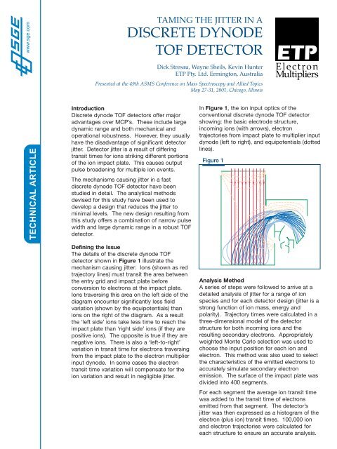
www.sge.comTAMING THE JITTER IN A<strong>DISCRETE</strong> <strong>DYNODE</strong><strong>TOF</strong> <strong>DETECTOR</strong>Dick Stresau, Wayne Sheils, Kevin HunterETP Pty. Ltd. Ermington, AustraliaPresented at the 49th ASMS Conference on Mass Spectroscopy and Allied TopicsMay 27-31, 2001, Chicago, IllinoisElectronMultipliersTECHNICAL ARTICLEIntroductionDiscrete dynode <strong>TOF</strong> detectors offer majoradvantages over MCP’s. These include largedynamic range and both mechanical andoperational robustness. However, they usuallyhave the disadvantage of significant detectorjitter. Detector jitter is a result of differingtransit times for ions striking different portionsof the ion impact plate. This causes outputpulse broadening for multiple ion events.The mechanisms causing jitter in a fastdiscrete dynode <strong>TOF</strong> detector have beenstudied in detail. The analytical methodsdevised for this study have been used todevelop a design that reduces the jitter tominimal levels. The new design resulting fromthis study offers a combination of narrow pulsewidth and large dynamic range in a robust <strong>TOF</strong>detector.In Figure 1, the ion input optics of theconventional discrete dynode <strong>TOF</strong> detectorshowing: the basic electrode structure,incoming ions (with arrows), electrontrajectories from impact plate to multiplier inputdynode (left to right), and equipotentials (dottedlines).Figure 1Defining the IssueThe details of the discrete dynode <strong>TOF</strong>detector shown in Figure 1 illustrate themechanism causing jitter: Ions (shown as redtrajectory lines) must transit the area betweenthe entry grid and impact plate beforeconversion to electrons at the impact plate.Ions traversing this area on the left side of thediagram encounter significantly less fieldvariation (shown by the equipotentials) thanions on the right of the diagram. As a resultthe ‘left side’ ions take less time to reach theimpact plate than ‘right side’ ions (if they arepositive ions). The opposite is true if they arenegative ions. There is also a ‘left-to-right’variation in transit time for electrons traversingfrom the impact plate to the electron multiplierinput dynode. In some cases the electrontransit time variation will compensate for theion variation and result in negligible jitter.Analysis MethodA series of steps were followed to arrive at adetailed analysis of jitter for a range of ionspecies and for each detector design (jitter is astrong function of ion mass, energy andpolarity). Trajectory times were calculated in athree-dimensional model of the detectorstructure for both incoming ions and theresulting secondary electrons. Appropriatelyweighted Monte Carlo selection was used tochoose the input position for each ion andelectron. This method was also used to selectthe characteristics of the emitted electrons toaccurately simulate secondary electronemission. The surface of the impact plate wasdivided into 400 segments.For each segment the average ion transit timewas added to the transit time of electronsemitted from that segment. The detector’sjitter was then expressed as a histogram of theelectron (plus ion) transit times. 100,000 ionand electron trajectories were calculated foreach structure to ensure an accurate analysis.
ResultsThe above method was used to design and evaluate avery effective jitter compensation electrode. Each of thehistograms generated by the method is essentially acalculation of the multiple ion pulse width that should beexpected from the first two stages of the detector.Measuring the pulse’s width at half maximum gives aconvenient, quantitative method of expressing eachanalysis result as a single number. To calculate theexpected total-detector pulse width (Figure 2, 3 and 4) thecalculated pulse width of the detector’s first two stages(jitter) has been added in quadrature to the detector’sexperimentally measured single ion pulse width:Figure 2W T= ((W J ) 2 +(W SI) 2 )–Figure 2, 3 & 4 show the variation in multiple ion pulsewidth as a function of ion mass and polarity for both theoriginal design and the jitter compensated design. In theoriginal design, the variation of electron transit time fromimpact plate to multiplier dynode compensates for thejitter caused by low-mass, positive ions, but causesgreater jitter for negative ions.Figure 3Although the jitter compensation is very effective, it isclear that the original design configuration will give better<strong>TOF</strong> performance in a system limited to positive ions andan energy dependant mass range (up to a mass of 6000amu for 10 keV ions).The ion’s contribution to jitter is a function of its velocity.Therefore, the jitter is a strong function of ion mass andenergy.Figure 4
Figure 5The 14880 discrete dynode<strong>TOF</strong> detector (below left) usedin this study (available eitherwith or without jittercompensation). The 14882(below right) is a floatingversion of the 14880 that hasthe signal isolated from thedetector output through 10kVdecoupling capacitors.Figure 5 shows the ion input optics of the jittercompensated discrete dynode <strong>TOF</strong> detector. Notehow all incoming ions traverse similar field variationsdue to the compensation electrode (upper left).ConclusionsInclusion of a jitter compensation electrode in adiscrete dynode <strong>TOF</strong> detector has reduced multipleion pulse width to ~3 nanoseconds for all ion massesand energies. The original (uncompensated) version<strong>TOF</strong> detector will give better <strong>TOF</strong> performance formost positive ion applications. Improvedperformance for negative ion applications will extendthe discrete dynode <strong>TOF</strong> detector’s use as thepreferred detector in a wider range of <strong>TOF</strong>applications, affording greater detector robustnessand dynamic range in systems previously restricted toMCP detectors.AcknowledgmentsWe would like to thank Alexander Makarov, Thermo Masslabs Ltd. (formerly of HDTechnologies), whose initial suggestions lead to this development project.A DIVISION OF <strong>SGE</strong> GROUP OF COMPANIESElectronMultiplierswww.etpsci.com<strong>SGE</strong> International Pty. Ltd.Tel: +61 (0) 3 9837 4200Fax: +61 (0) 3 9874 5672Email: techsupport@etpsci.com<strong>SGE</strong>, Incorporated (USA)Toll Free: (800) 945 6154Fax: (512) 836 9159Email: usa@sge.com© Copyright 2001 <strong>SGE</strong> International Pty. Ltd. All rights reserved. TA-0097-A<strong>SGE</strong> Europe LtdTel: +44 (0) 1908 568844Fax: +44 (0) 1908 566790Email: uk@sge.comwww.sge.com