Create successful ePaper yourself
Turn your PDF publications into a flip-book with our unique Google optimized e-Paper software.
CMS Tracker<strong>Silicon</strong> Strip SensorFront-EndElectronicsM.Friedl: <strong>Silicon</strong> <strong>Detector</strong> <strong>Readout</strong> 14 June 20124
Various CMS Tracker ModulesElectronicsSensorsM.Friedl: <strong>Silicon</strong> <strong>Detector</strong> <strong>Readout</strong> 14 June 20126
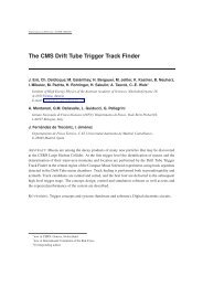
<strong>Silicon</strong> Strip <strong>Detector</strong>sWire bondCMS Test Sensor with various geometries (1998) Belle Sensor with 45° strips (2004)• Typically 300µm thick, strip pitch 50...200µm• Reverse bias voltage for full depletion 50...500V• Connection by wire bondsM.Friedl: <strong>Silicon</strong> <strong>Detector</strong> <strong>Readout</strong> 14 June 20127
<strong>Silicon</strong> Pixel <strong>Detector</strong>sCMS Pixel <strong>Readout</strong> Scheme CMS Pixel Sensor ATLAS Pixel Sensor• Pixels can be square (CMS) or oblong (ATLAS)• Structure size similar to strip detectors, but N 2 channels• Connection by bump bondsM.Friedl: <strong>Silicon</strong> <strong>Detector</strong> <strong>Readout</strong> 14 June 20128
Principle of Operationcharged particle trackFront-end amplifier+E+-+-+---+++p -implantn-type bulkn + -implant• p-n junction is operated at reverse bias to drain free carriers• Traversing charged particle creates electron-hole pairs• Carriers drift towards electrodes in the electric field• Moving carriers induce current in the circuit → current sourceM.Friedl: <strong>Silicon</strong> <strong>Detector</strong> <strong>Readout</strong> 14 June 20129
Equivalent Circuit of the <strong>Detector</strong>IC detCurrent source withcapacitor in parallel• Applies to many types of detectors, not only silicon• Example: wire chamberCoaxial capacitor configurationMoving charges induce current• Example: photomultiplier tubeSmall platesCharge (current) is amplified in each stageM.Friedl: <strong>Silicon</strong> <strong>Detector</strong> <strong>Readout</strong> 14 June 201210
Comparison: Voltage vs. Current SourceProperty Voltage Source Current SourceIDEALVoltage constant + anythingCurrent anything V constantIdle (no power) Open (I=0) Shorted (V=0)IProperty Voltage Source Current SourceREAL(Linear) equivalentcircuit+VR VResistor causes Internal voltage drop Internal current dropIR IConversionNorton-Thevenin equivalent: R V = R I ; V = I R V/IExamplesBatteryWall plug (AC)<strong>Detector</strong>NIM module outputsM.Friedl: <strong>Silicon</strong> <strong>Detector</strong> <strong>Readout</strong> 14 June 201211
Moving ChargesM.Friedl: <strong>Silicon</strong> <strong>Detector</strong> <strong>Readout</strong> 14 June 201212
Ramo’s Theorem (1939)• Moving charges between inside electric field (e.g. parallelplates) induces current in electrodesi = E q v• Current is proportional to electric field E, (moving) charge qand velocity v of the charge• It doesn’t matter if the charges eventually reach theelectrodes or not, only motion counts• Fully valid for parallel plate capacitor configuration (largearea diode)• A bit more complicated for strip detectors → more laterM.Friedl: <strong>Silicon</strong> <strong>Detector</strong> <strong>Readout</strong> 14 June 201213
A Bit of Theory+• Space chargedensity is given bydoping• Electric field iscalculated byPoisson’s equation• Potential is found byintegration of fieldn +0ρeNEn-type bulkp +DxxE maxϕ• Shown here: fulldepletion = spacecharge just extendsover full detector-V deplxxM.Friedl: <strong>Silicon</strong> <strong>Detector</strong> <strong>Readout</strong> 14 June 201214
Bias Voltage and Depletion• In reality, the electric field is imposed by applied bias voltage• What happens if V bias < V depl ?Electric field does not cover full bulkOnly part of detector contributes tocharge collection → lower efficiencyDo not operate a detector like that• What happens if V bias > V depl ?Linear offset is added to electric fieldField tends to become more flatFaster charge collection (Ramo)Limited by breakdown voltageEExxM.Friedl: <strong>Silicon</strong> <strong>Detector</strong> <strong>Readout</strong> 14 June 201215
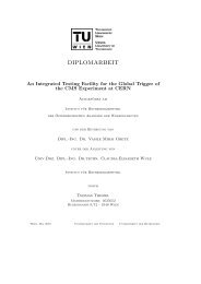
Induced Currents (1)i [nA]600500400300200100<strong>Detector</strong> Currents -- E lectrons and Holes ContributionsD=300µm, r=4kΩcm, V=79/158VV=V depl 8007006005004003002001000i [nA]1000900V=2 V deplisum0 5 10 15 20time [ns]ieih00 5 10 15 20 25 30 35 40 45 50time [ns]M.Friedl: <strong>Silicon</strong> <strong>Detector</strong> <strong>Readout</strong> 14 June 201216
Induced Currents (2)• Typical silicon detector (D=300µm)• Very low (
Induced Currents (3)• Both electrons and holes contribute to overall current, butcannot be distinguished in reality• Integral over time (area under curve) is the collected chargeIf all charges reach electrodes, this is identical to the number ofcreated pairs∫ i dt ≈ 3.6 fC ≡ 22500 e for a 300µm thick detectorFor comparison: ~10 10 e every 20ns in a 25W bulb (230VAC)• In a simple parallel plate geometry, contributions ofelectrons and holes are equalHowever, it’s not that simple in a strip detector…M.Friedl: <strong>Silicon</strong> <strong>Detector</strong> <strong>Readout</strong> 14 June 201218
Induced Current Measurement• Quite difficult due to noise constraints<strong>Detector</strong> Currents -- E lectrons and Holes ContributionsD=300µm, r=4kΩcm, V=79/158Visum600500400V=V deplSingle shoti [nA]300200100Averaged00 5 10 15 20 25 30 35 40 45 50time [ns]• Every amplifier has a limited bandwidth and thus rise time• Nonetheless, exponential decay is clearly visibleM.Friedl: <strong>Silicon</strong> <strong>Detector</strong> <strong>Readout</strong> 14 June 201219
Strip <strong>Detector</strong> Case• Ramo theorem still holds, but with some modifications• Why?Charge movement is determined by electric field (which isapproximately the same as for the parallel plate case)Induced currents are calculated by (virtual) weighting fieldNow the moving charges influence a current onto several stripsdepending on the geometry and distance• How to calculate weighting field?Electrode under consideration is held at unity potential, allother electrodes at zeroM.Friedl: <strong>Silicon</strong> <strong>Detector</strong> <strong>Readout</strong> 14 June 201220
Strip <strong>Detector</strong> Simulation (1)• 300 µm thick, 50 µm pitch, n-bulk, p-strips, V bias =1.6 x V deplDrift Potential & FieldLinear color scale!M.Friedl: <strong>Silicon</strong> <strong>Detector</strong> <strong>Readout</strong> 14 June 201221
Strip <strong>Detector</strong> Simulation (2)• 300 µm thick, 50 µm pitch, n-bulk, p-strips, V bias =1.6 x V deplWeighting Potential & FieldNonlinear color scale!M.Friedl: <strong>Silicon</strong> <strong>Detector</strong> <strong>Readout</strong> 14 June 201222
Strip <strong>Detector</strong> Simulation (3)• 300 µm thick, 50 µm pitch, n-bulk, p-strips, V bias =1.6 x V deplInduced currentssumh +e -Integratedcurrents:Q e- = 3338 eQ h+ = 20019 eQ sum = 23356 eMeasured chargeis dominated byholes:86% @ p=50µm82% @ p=75µm77% @ p=120µm…53% @ p=500µmM.Friedl: <strong>Silicon</strong> <strong>Detector</strong> <strong>Readout</strong> 14 June 201223
Strip <strong>Detector</strong> Case• Due to the very nonlinear weighting field, the charges whichdrift towards the electrode largely dominate the overallinduced current• Doesn’t seem very relevant, but it actually has practicalimplications → Lorentz shiftM.Friedl: <strong>Silicon</strong> <strong>Detector</strong> <strong>Readout</strong> 14 June 201224
Lorentz Shift• In a magnetic field, charge movement is deflected due toLorentz force which depends on the carrier mobility• Resulting in an angle (approximately ~12° for e, ~4° for h at1.8T) and spreading of signals over several stripsParticlefrom IPh +e -B||zn-sideshort strips along r-phi+HVp-sidelong strips along z-HVM.Friedl: <strong>Silicon</strong> <strong>Detector</strong> <strong>Readout</strong> 14 June 201225
Lorentz Shift Compensatione - h +n-sideshort strips along r-phi+HVe -Particlefrom IPp-sidelong strips along z-HVB||zh +Particlefrom IPBzBzM.Friedl: <strong>Silicon</strong> <strong>Detector</strong> <strong>Readout</strong> 14 June 201226
<strong>Silicon</strong> <strong>Detector</strong> Summary• Various Geometries:(Diode), strips, pixels• <strong>Detector</strong> is a current source || capacitancep-n junction operated under reverse bias voltage > V depl• Charged particle creates electron-hole pairsCarrier motion in the electric field induces current on electrodesSignal is typically
• <strong>Silicon</strong> <strong>Detector</strong>• Front-End Amplifier• Signal Transmission• Back-End Signal Processing• SummaryM.Friedl: <strong>Silicon</strong> <strong>Detector</strong> <strong>Readout</strong> 14 June 201228
Front-End Amplifier PrincipleI inV outPreamplifier(Integrator)Shaper(Filter)• Located close to the sensor• First stage: Integrator<strong>Detector</strong> current → charge• Second stage: FilterLimit bandwidth to reduce noiseM.Friedl: <strong>Silicon</strong> <strong>Detector</strong> <strong>Readout</strong> 14 June 201229
Shaper Bandwidth Reduction• Example: APV25 front-end amplifier (CMS)AVG Noise APV 13025Amplitude [a.u.]Nosie [ADC]2015105Frequency01.E+02 1.E+03 1.E+04 1.E+05 1.E+06 1.E+07 1.E+08Frequency [Hz]SimulationMeasurementM.Friedl: <strong>Silicon</strong> <strong>Detector</strong> <strong>Readout</strong> 14 June 201230
Example: VA2 Chip Input Stage• VA2 is a general-purpose front-end amplifier chip with 128inputs and multiplexed output• “Slow” shaper in the µs range ≡ low noiseM.Friedl: <strong>Silicon</strong> <strong>Detector</strong> <strong>Readout</strong> 14 June 201231
Shaper OutputTp~2µsAmplitudeVA2General purposeTp~50nsTimeAmplitudeAPV25CMSParticle hitTime• T p …shaping time (or peaking time)• Faster shaping can be a necessity of the experiment todistinguish subsequent events, but also implies larger noiseM.Friedl: <strong>Silicon</strong> <strong>Detector</strong> <strong>Readout</strong> 14 June 201232
“Low-Noise” Amplifiers• Nearly all front-end chips are called “low-noise”• General feature of the integrator+shaper combination• Noise is typically given by ENC (equivalent noise charge)referred to the input• ENC = a + b ⋅ C det (a,b...const, C det ...detector capacitance)• Examples:T p [ns]ENC [e]VA2 (~1993) 2000 60 + 11 / pFAPV25 (CMS, 1999) 50 250 + 36 / pF• How can noise depend on the detector capacitance?M.Friedl: <strong>Silicon</strong> <strong>Detector</strong> <strong>Readout</strong> 14 June 201233
Simplified Noise Modelv sIC deti pAmplifier noise,projected to the input• Amplifier noise is projected to voltage noise source andcurrent noise source at input• Integrator measures charge (integrated current)• Superposition analysis (one by one, other voltage sourcesare closed, other current sources are open; very simplified):Q n = ∫ i p dt + C det ⋅ V s = a + b ⋅ C det = ENCM.Friedl: <strong>Silicon</strong> <strong>Detector</strong> <strong>Readout</strong> 14 June 201234
Full Chip Example: APV25 (CMS)For each of the 128 channelsMUX gaininverterpipeline128:1MUXDifferentialcurrentoutput amppreampshaperAPSPS/H• Shaping time: 50ns, sampling: 40MHz• Analog pipeline (192 cells) to store data untiltrigger arrives, optional APSP filter, 128:1multiplexer, differential output driver8.1mmM.Friedl: <strong>Silicon</strong> <strong>Detector</strong> <strong>Readout</strong> 14 June 2012357.1mm
APV25 in ActionSensorPitchAdapterAPV25BondwiresHybridM.Friedl: <strong>Silicon</strong> <strong>Detector</strong> <strong>Readout</strong> 14 June 201236
Shaper Output Sampling• Usually, shaper output is sampled once at the peakThen those values are multiplexed (1:128) to the outputPeak sampleAmplitudeParticle hit• The timing is given by a constant offset from the particle hit(as supplied by an external trigger, e.g. scintillator)• What happens if there are several particles with differenttiming?M.Friedl: <strong>Silicon</strong> <strong>Detector</strong> <strong>Readout</strong> 14 June 201237Time
Pile-up Events• Strip detector measurement in a high intensity beam• Trigger – hit ambiguities and non-peak sampling can occur“pileups”Trigger from this particleAlso returns several other samples > 0!M.Friedl: <strong>Silicon</strong> <strong>Detector</strong> <strong>Readout</strong> 14 June 201238
How to Avoid Such Ambiguities?• Better timing information implies more data, more energyand/or a higher noise figure• Faster Shaping = narrower output pulsesLimited by noise performance• On-chip pulse shape processing (APV25)“Deconvolution” filter which processes samples and essentiallynarrows down the output to a single bunch crossing• Off-chip data processingUsing multiple subsequent samples and apply a pulse shape fitM.Friedl: <strong>Silicon</strong> <strong>Detector</strong> <strong>Readout</strong> 14 June 201239
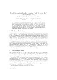
Hit Time Finding• Shaper output curve is well known with two parametersPeak amplitude, peak timing• Event-by-event fit of shaping curve determines those twoTiming resolution of ~3ns (RMS) measured with APV25Signal [e]3500030000250002000015000strips= 317 - 320clwidth=4tmax=89.25 nsamp=34775 echi2/ndf=5.695e+00Data above thresholdData below thresholdIntCal fitentries []500400300(cal. fit (spline) - TDC) p sideh_tdc_cal_diff_0_1_pyEntries 13155Mean 0.02441RMS 2.281Underflow 0Overflow 02c / ndf148.4 / 97Constant 480.5 ±5.3Mean1.568e-09 ±1.900e-02Sigma 2.16 ±0.011000020050000Threshold0 50 100 150 200 250 300Time [ns]1000-15 -10 -5 0 5 10 15tpeak_cal-tpeak_TDC [ns]M.Friedl: <strong>Silicon</strong> <strong>Detector</strong> <strong>Readout</strong> 14 June 201240
Occupancy ReductionBelleSVD2VA1TATp~800nsBelle → Belle II:40 x increase in luminosityThresholdTime over threshold ~ 2000ns (measured)Belle IISVDAPV25Tp~50nsThresholdGain ~12.5Belle IISVD withHit time findingTime over threshold ~ 160ns (measured)Pulse shapeprocessingRMS(tmax)~3nsSensitive time window ~ 20nsGain ~8Total gain ~100Markus Friedl (<strong>HEPHY</strong> Vienna): Status of SVD 12 November 201141
Front-End Amplifier Summary• Integrated circuits with typically 128 channels• 2 stages:Preamplifier (integrator: current → charge)Shaper (band-pass filter to reduce noise)• Noise is referred to input and expressed as charge: ENC = a + b ⋅ C det (a,b...const, C det ...detector capacitance)• Shaper bandwidth determined speed and noiseFast ≡ large noise; slow ≡ low noiseRequired speed is usually defined by the experimentSlow shaping and pile-up can lead to ambiguitiesTricks to circumvent speed limitation, e.g. hit time findingM.Friedl: <strong>Silicon</strong> <strong>Detector</strong> <strong>Readout</strong> 14 June 201242
• <strong>Silicon</strong> <strong>Detector</strong>• Front-End Amplifier• Signal Transmission• Back-End Signal Processing• SummaryM.Friedl: <strong>Silicon</strong> <strong>Detector</strong> <strong>Readout</strong> 14 June 201243
Why?• <strong>Detector</strong> front-end is usually quite crowdedRadiation environment does not allow commercial electronicsMaterial budget should be as low as possiblePower consumption as well (requires cooling = material)• Thus, only inevitable electronics is put at the front-end• Everything else is conveniently located in a separate roomoutside the detector, traditionally called “counting house”Allows access during machine and detector operationM.Friedl: <strong>Silicon</strong> <strong>Detector</strong> <strong>Readout</strong> 14 June 201244
Example: CMS Experiment• Electronics hall is almostas big as experimentalcavern• Signal distance up to100m• Huge amount of signaltransmission linesElectronicscavernExperimentalcavernM.Friedl: <strong>Silicon</strong> <strong>Detector</strong> <strong>Readout</strong> 14 June 201245
Generic Transmission Chain< 2m up to 100mFront-endRepeater• Signal directions<strong>Readout</strong> (large amount): front-end to back-end,analog or digitalControls (small amount): back-end to front-end,digital (clock, trigger, settings)• Usually, the front-end chips cannot drive the full pathRepeater (driver/receiver) is needed to amplify signalsBack-endM.Friedl: <strong>Silicon</strong> <strong>Detector</strong> <strong>Readout</strong> 14 June 201246
Excursion: Electrical Signal TransmissionV SR SR L• Single-endedagainst GNDHuge ground loopGND compensation≈R SR L• Single-ended incoaxial cableNo ground loopGND compensationV S+(from APV)EL5173-150pF50Ω50Ω150pF30m CAT7 cable100ΩADCdaughterboard(~100MHzbandwidth)(to PC)• Differential twistedpair (+shield)Largely immuneM.Friedl: <strong>Silicon</strong> <strong>Detector</strong> <strong>Readout</strong> 14 June 201247
Cable Bandwidth• Every cable has a finite bandwidth / dampingNonlinear attenuation with rising frequency• Example: CAT7network cable(shieldedtwisted pairs)• Significantespecially foranalog signaltransmissionNormalized loss [dB]10-1-2-3-4-5-6-7TheoryMeasurement30m CAT7 Transfer Function1 10 100Frequency [MHz]M.Friedl: <strong>Silicon</strong> <strong>Detector</strong> <strong>Readout</strong> 14 June 201248
Alternative: Optical Fiber• Fibers have extremely high bandwidth and very little loss• Also automatically provide electrical isolation betweensender and receiver sides• However: requires conversion on both ends, which makes anoptical link more expensive than a cable• Best suitable for long-haul, high-speed digital datatransmission such as telecom• Nonetheless also often used in HEP experiments• Optical transmission usually implies digital signals with NRZcoding (pure AC signal with only very short DC sequences)M.Friedl: <strong>Silicon</strong> <strong>Detector</strong> <strong>Readout</strong> 14 June 201249
Comparison: Copper vs. Optical FiberProperty Copper Cable Optical FiberCable rigid delicate (e.g. radius)Connectors huge variety few standardsSize/weight large smallBandwidth limited highLoss high lowDriver + receiver cheap expensiveLevel isolation no yesM.Friedl: <strong>Silicon</strong> <strong>Detector</strong> <strong>Readout</strong> 14 June 201250
Example: CMS Tracker (1)• Optical fiber required because of material budget<strong>Detector</strong> ModuleClock & TriggerResetControl (I2C)AnalogOptohybridLLD1MU-sMUPatchPanel1296MFSPatchPanelAnalogReceiverDAQInterfaceDataProcessingTTCrxFEDAnalog Optical LinkParameters37,000 channels100m fiber length1310nm infrared lightStep-index single-mode fiberIntensity modulation40MHz readout speedI2C control interfaceExperimental Cavern: Radiation ZoneCounting Room• Exceptional case: analog optical transmissionSpecial requirements for linearity, gain stability and noiseM.Friedl: <strong>Silicon</strong> <strong>Detector</strong> <strong>Readout</strong> 14 June 201251
Example: CMS Tracker (2)Analog OptohybridMU-sMU ConnectionMFS ConnectionRugged Multi-Ribbon CableAnalogReceiverASICAnalog Rx ModuleLaser Transmitter• Several components are customized and thus expensiveO(10000) are small quantities for industry• Estimated cost per link: ~150 € (cf. ~15 € with cable)M.Friedl: <strong>Silicon</strong> <strong>Detector</strong> <strong>Readout</strong> 14 June 201252
Example: Belle II <strong>Silicon</strong> Vertex <strong>Detector</strong>• Analog APV25 readout is through copper cable to FADCs• Junction box provides LV to front-end• APV25 drives 12m cables!1748APV25chips~2mcoppercableJunctionbox~10mcoppercableFA DC +P R OCFinesse TransmitterBoard (FTB)Unified opticaldata link (>20m)COPPERFront-endhybridsRad-hardDC/DCconvertersAnalog level translation,data sparsification andhit time reconstructionUnified Belle IIDAQ systemM.Friedl: <strong>Silicon</strong> <strong>Detector</strong> <strong>Readout</strong> 14 June 201253
Example: Belle II <strong>Silicon</strong> Vertex <strong>Detector</strong>• Using same APV25 chip as in CMS, but much shorterdistance → no optical link required• Analog signals are attenuated in long copper cableFirst attempt was an analog equalizer chip (enhancing higherfrequencies) with moderate successLater tried purely digital filter after digitizationPerfect regeneration with digital signal processing (FIR filter) atthe back-end inside an FPGAMultiplication of 8 consecutive samples with 8 filter coefficientsand summing in real-time (40 MHz)M.Friedl: <strong>Silicon</strong> <strong>Detector</strong> <strong>Readout</strong> 14 June 201254
Example: Belle II <strong>Silicon</strong> Vertex <strong>Detector</strong>Optimized channelNon-optimized channelRaw APV25 outputwithoutFIR• FIR filter with 8 coefficients operating continuously at 40MHz• Removes cable loss and reflections due to imperfect termination!M.Friedl: <strong>Silicon</strong> <strong>Detector</strong> <strong>Readout</strong> 14 June 201255
Signal Transmission Summary• Signals of large number of readout channels to betransmitted to back-end for data processing• Options: copper cable or optical fiber• Copper is much cheaper, but has frequency-dependent lossCan be compensated e.g. with digital FIR filter at back-end• Optical links are more complicated to handleUsually digital with NRZ codingException: CMS Tracker uses analog optical linksM.Friedl: <strong>Silicon</strong> <strong>Detector</strong> <strong>Readout</strong> 14 June 201256
• <strong>Silicon</strong> <strong>Detector</strong>• Front-End Amplifier• Signal Transmission• Back-End Signal Processing• SummaryM.Friedl: <strong>Silicon</strong> <strong>Detector</strong> <strong>Readout</strong> 14 June 201257
Purpose of the Back-End• Perform all the steps which can’t be done in the front-endFront-end ADC FPGADAQ• <strong>Readout</strong> chain:Receiver (electrical or optical), digitization (if analog input),data processing and reduction in FPGA (field programmablegate array), output to DAQ (data acquisition)• Receiver for clock, trigger and controls (centrally distributed)M.Friedl: <strong>Silicon</strong> <strong>Detector</strong> <strong>Readout</strong> 14 June 201258
Example: CMS-Pixel-FED• FED means “FrontEnd Driver”(misleading)• Contains all theelementsmentioned beforeAnalog optical receiversADCsFPGAsCLK, TriggerFPGAsFPGATo DAQM.Friedl: <strong>Silicon</strong> <strong>Detector</strong> <strong>Readout</strong> 14 June 201259
Boards and Crates• Such boards are typically built according to a certain(industrial) standard bus system“Standard”: VME (Versa Module Eurocard), size 9UObsolete: CAMAC, FastbusModern: µTCA• All those standards describeGeometry of modulesElectrical interface, power supplyBus system for communication with crate controller & PC• Organized in crates and racksM.Friedl: <strong>Silicon</strong> <strong>Detector</strong> <strong>Readout</strong> 14 June 201260
VME (9U) CratesEmpty crateas sold by industryBelle I <strong>Silicon</strong>Vertex <strong>Detector</strong>(cable input)CMS Pixel-FED(optical input)M.Friedl: <strong>Silicon</strong> <strong>Detector</strong> <strong>Readout</strong> 14 June 201261
What’s an FPGA?• FPGA is a huge array of logical gates which can be combinedaccording to the user’s need• Programming by software using basic gates & library blockse.g. and, adder, latch, …, CPU coreEither by schematics or by VHDL programming languageM.Friedl: <strong>Silicon</strong> <strong>Detector</strong> <strong>Readout</strong> 14 June 201262
Comparison: FPGA vs. CPUProperty FPGA CPUParallelism any a few coresSpeed (clock) O(100MHz) O(1GHz)I/O lines O(1000) 64Best suitable forAt the back-endFast, simple, massiveparallel processingFirst low-level datareductionComplex, serial programsHigh-level dataprocessing (DAQ)M.Friedl: <strong>Silicon</strong> <strong>Detector</strong> <strong>Readout</strong> 14 June 201263
Example: APV25 Output Data StreamAmplitude [ADC]headerHit dataData frameidleStrip data (pedestals)Time [25ns]M.Friedl: <strong>Silicon</strong> <strong>Detector</strong> <strong>Readout</strong> 14 June 201264
Strip Data Composition• Analog signal output of one event is a multiplexed stream of128 data values, but not just the actual strip signalADC i = S i + N i + P i + CMNi…strip numberADC i …measured amplitude in ADC unitsS i …particle signalN i …noise (random fluctuations)P i …pedestal (zero value; individual for each strip)CMN…common mode noise (common to all strips in one event)• Pedestal and noise can be measured and saved for eachchannel, CMN is removed event-by-eventM.Friedl: <strong>Silicon</strong> <strong>Detector</strong> <strong>Readout</strong> 14 June 201265
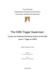
How to Process Strip Data?ADCADCADC300200100402006040200(a)(b)(c)50 100 150 200 250Raw datastrip50 100 150 200 250Pedestal subtractedstrip50 100 150 200 250After common mode correctionstrip• Data stream withindividualpedestals (dots)• Dominated bypedestal variationM.Friedl: <strong>Silicon</strong> <strong>Detector</strong> <strong>Readout</strong> 14 June 201266Signal• Pedestals subtracted,common mode noise andindividual strip noiseremains• After commom modecorrection, average is atzero with random noiseexcursions for each strip• Next: Apply hit threshold
Typical Tasks for <strong>Silicon</strong> Strip <strong>Detector</strong>DigitizationFrame DetectionR eorderingPedes tal S ubtractionCMC (2-pass)Hit FindingTime FindingFPGA ADC• ADC converts data to digital• Find and extract strip data• Put the strip data in natural order(needed if entangled, e.g. APV25)• Subtract zero value for each strip• Remove common-mode noise(appears on all strips in common)• Apply hit threshold (zero suppression,sparsification) = keep only hit data• Optional post-processing (e.g. APV25)M.Friedl: <strong>Silicon</strong> <strong>Detector</strong> <strong>Readout</strong> 14 June 201267
FPGA Limits• Simple state machine, but no complex programming(instruction list) as with a CPU• Typically integer arithmetic• Made for fast I/O and throughput; internal memory is limited• Ideal for first stage of data processing – O(10) times morethroughput than a state-of-the-art CPU• More complex operations at a later stage with reduced dataare performed on CPU farms (DAQ)M.Friedl: <strong>Silicon</strong> <strong>Detector</strong> <strong>Readout</strong> 14 June 201268
Back-End Signal Processing Summary• Performs digitization, data processing (reduction) andoutput to subsequent DAQ (computer farm) stagePedestal subtraction, common mode correction, zerosuppression• Boards following a bus module standardE.g. VME (9U)• Organized in crates and racks• Typically uses FPGAs (field programmable logic arrays)Ideal for low-level massive parallel processingMore powerful than CPUs for such tasksComplex calculations are done in subsequent computer farmM.Friedl: <strong>Silicon</strong> <strong>Detector</strong> <strong>Readout</strong> 14 June 201269
• <strong>Silicon</strong> <strong>Detector</strong>• Front-End Amplifier• Signal Transmission• Back-End Signal Processing• SummaryM.Friedl: <strong>Silicon</strong> <strong>Detector</strong> <strong>Readout</strong> 14 June 201270
Thank you for your attention!M.Friedl: <strong>Silicon</strong> <strong>Detector</strong> <strong>Readout</strong> 14 June 201271