ADVANTAGE 400 - Paint Sprayers, HVLP Sprayers, Powered Rollers
ADVANTAGE 400 - Paint Sprayers, HVLP Sprayers, Powered Rollers
ADVANTAGE 400 - Paint Sprayers, HVLP Sprayers, Powered Rollers

Create successful ePaper yourself
Turn your PDF publications into a flip-book with our unique Google optimized e-Paper software.
Owner’s ManualDo not use this equipmentbefore reading this manual!<strong>ADVANTAGE</strong> <strong>400</strong>Electric Piston PumpModel Numbers:Stand 0552054Upright Cart 0552071Lowboy Cart 0552072NOTE: This manual contains importantwarnings and instructions. Pleaseread and retain for reference.1110 • © Titan Tool Inc. All Rights Reserved. Form No. 0552841C
Important Safety Information · Read all safety information beforeoperating the equipment. Save these instructions.This symbol indicates a hazardous situation,which, if not not avoided could result in death orserious injury.To reduce the risks of fire or explosion, electricalshock and the injury to persons, read andunderstand all instructions included in this manual.Be familiar with the controls and proper usage ofthe equipment.HAZARD: Injection injuryA high pressure paint stream produced by thisequipment can pierce the skin and underlyingtissues, leading to serious injury and possibleamputation. See a physician immediately.DO NOT TREAT AN INJECTION INJURY AS A SIMPLECUT! Injection can lead to amputation. See a physicianimmediately.The maximum operating range of the sprayer is 3000 PSI / 20.7MPa fluid pressure.PREVENTION:• NEVER aim the gun at any part of the body.• Do not aim the gun at, or spray any person or animal.• NEVER allow any part of the body to touch the fluid stream.DO NOT allow body to touch a leak in the fluid hose.• NEVER put your hand in front of the gun. Gloves will notprovide protection against an injection injury.• ALWAYS lock the gun trigger, shut the pump off, andrelease all pressure before servicing, cleaning the tip orguard, changing tip, or leaving unattended. Pressure willnot be released by turning off the motor. The PRIME/SPRAY valve or pressure bleed valve must be turned totheir appropriate positions to relieve system pressure.Refer to the PRESSURE RELIEF PROCEDUREdescribed in this manual.• ALWAYS keep the tip guard in place while spraying. Thetip guard provides some protection but is mainly a warningdevice.• ALWAYS remove the spray tip before flushing or cleaningthe system.• <strong>Paint</strong> hose can develop leaks from wear, kinking andabuse. A leak can inject material into the skin. Inspectthe hose before each use. Do not use hose to lift or pullequipment.• NEVER use a spray gun without a working trigger lock andtrigger guard in place.• All accessories must be rated at or above 3000 PSI / 20.7MPa. This includes spray tips, guns, extensions, and hose.• Do not leave the unit energized or under pressure whileunattended. When the unit is not in use, turn off theunit and relieve the pressure in accordance with thePRESSURE RELIEF PROCEDURE described in thismanual.• Verify that all connections are secure before operating theunit. Unsecured parts may eject at great force or leak ahigh pressure fluid stream causing severe injury.• Always engage the trigger lock when not spraying. Verifythe trigger lock is functioning properly.note to physician:Injection into the skin is a traumatic injury. It isimportant to treat the injury as soon as possible. DONOT delay treatment to research toxicity. Toxicity is aconcern with some coatings injected directly into theblood stream. Consultation with a plastic surgeon orreconstructive hand surgeon may be advisable.HAZARD: HAZARDOUS VAPORS<strong>Paint</strong>s, solvents, insecticides, and other materialscan be harmful if inhaled or come in contact with thebody. Vapors can cause severe nausea, fainting, orpoisoning.PREVENTION:• Use a respirator or mask if vapors can beinhaled. Read all instructions suppliedwith the mask to be sure it will provide thenecessary protection.• Wear protective eyewear.• Wear protective clothing as required by coating manufacturer.HAZARD: EXPLOSION OR FIRESolvent and paint fumes can explode or ignite.Property damage and/or severe injury can occur.PREVENTION:• Provide extensive exhaust and fresh airintroduction to keep the air within the spray area free fromaccumulation of flammable vapors. Solvent and paintfumes can explode or ignite.• Do not spray in a confined area.• Avoid all ignition sources such as staticelectric sparks, open flames, pilot lights,electrical appliances, and hot objects.Connecting or disconnecting powercords or working light switches can makesparks. <strong>Paint</strong> or solvent flowing through theequipment is able to result in static electricity.• Do not smoke in spray area.• Fire extinguisher must be present and in good workingorder.• Place pump at least 25 feet (7.62 meters) from thespray object in a well ventilated area (add more hose ifnecessary). Flammable vapors are often heavier than air.Floor area must be extremely well ventilated. The pumpcontains arcing parts that emit sparks and can ignite vapors.• The equipment and objects in and around the spray areamust be properly grounded to prevent static sparks.• Keep area clean and free of paint or solvent containers,rags and other flammable materials.• Use only conductive or grounded high pressure fluid hose.Gun must be grounded through hose connections.• For electric units — power cord must be connected to agrounded circuit.• Always flush unit into a separate metal container, at lowpump pressure, with spray tip removed. Hold gun firmlyagainst side of container to ground container and preventstatic sparks.• Follow the material and solvent manufacturer’s warningsand instructions. Know the contents of the paints andsolvents being sprayed. Read all Material Safety DataSheets (MSDS) and container labels provided withthe paints and solvents. Follow the paint and solventmanufacturer’s safety instructions.• Use extreme caution when using materials with a flashpointbelow 70ºF (21ºC). Flashpoint is the temperature that afluid can produce enough vapors to ignite.• Plastic can cause static sparks. Never hang plastic toenclose a spray area. Do not use plastic drop cloths whenspraying flammable materials.• Use lowest possible pressure to flush equipment.• Do not spray onto pump assembly.2 © Titan Tool Inc. All rights reserved.
Important Safety Information · Read all safety information beforeoperating the equipment. Save these instructions.HAZARD: EXPLOSION HAZARD DUE TOINCOMPATIBLE MATERIALSWill cause property damage or severe injury.PREVENTION:• Do not use materials containing bleach or chlorine.• Do not use halogenated hydrocarbon solvents suchas bleach, mildewcide, methylene chloride and 1,1,1 -trichloroethane. They are not compatible with aluminum.• Contact your coating supplier about the compatibility ofmaterial with aluminum.HAZARD: GENERALCan cause severe injury or property damage.PREVENTION:• Read all instructions and safety precautions beforeoperating equipment.• Follow all appropriate local, state, and national codesgoverning ventilation, fire prevention, and operation.• The United States Government Safety Standards havebeen adopted under the Occupational Safety and HealthAct (OSHA). These standards, particularly part 1910 ofthe General Standards and part 1926 of the ConstructionStandards should be consulted.• Use only manufacturer authorized parts. User assumesall risks and liabilities when using parts that do not meetthe minimum specifications and safety requirements of thepump manufacturer.• All hoses, fittings, and filter parts must be secured beforeoperating spray pump. Unsecured parts can eject at greatforce or leak a high pressure fluid stream causing severeinjury.• Before each use, check all hoses for cuts, leaks, abrasionor bulging of cover. Check for damage or movement ofcouplings. Immediately replace the hose if any of theseconditions exist. Never repair a paint hose. Replace it withanother grounded high-pressure hose.• Do not kink or over-bend the hose. Airless hose candevelop leaks from wear, kinking and abuse. A leak caninject material into the skin.• Do not expose the hose to temperatures or pressures inexcess of those specified by manufacturer.• Do not spray outdoors on windy days.• Wear clothing to keep paint off skin and hair.• Do not operate or spray near children. Keep childrenaway from the equipment at all times.• Do not overreach or stand on an unstable support. Keepeffective footing and balance at all times.• Use lowest possible pressure to flush equipment.• Stay alert and watch what you are doing.• Do not operate the unit when fatigued or under theinfluence of drugs or alcohol.• For electric units — Always unplug cord from outlet beforeworking on equipment.• Do not use the hose as a strength member to pull or lift theequipment.• Do not lift by cart handle when loading or unloading.Grounding InstructionsThis product must be grounded. In the event of an electricalshort circuit, grounding reduces the risk of electric shock byproviding an escape wire for the electric current. This product isequipped with a cord having a grounding wire with an appropriategrounding plug. The plug must be plugged into an outlet thatis properly installed and grounded in accordance with all localcodes and ordinances.WARNING - Improper installation of the groundingplug can result in a risk of electric shock.If repair or replacement of the cord or plug is necessary, do notconnect the green grounding wire to either flat blade terminal.The wire with insulation having a green outer surface withor without yellow stripes is the grounding wire and must beconnected to the grounding pin.Check with a qualified electrician or serviceman if the groundinginstructions are not completely understood, or if you are in doubtas to whether the product is properly grounded. Do not modifythe plug provided. If the plug will not fit the outlet, have theproper outlet installed by a qualified electrician.Grounded OutletGrounding PinCover for grounded outlet boxImportant: Use only a 3-wire extension cord that hasa 3-blade grounding plug and a 3-slot receptacle that willaccept the plug on the product. Make sure your extensioncord is in good condition. When using an extension cord,be sure to use one heavy enough to carry the current yourproduct will draw. An undersized cord will cause a drop inline voltage resulting in loss of power and overheating. A 12gauge cord is recommended. If an extension cord is to beused outdoors, it must be marked with the suffix W-A afterthe cord type designation. For example, a designation ofSJTW-A would indicate that the cord would be appropriatefor outdoor use.SpecificationsGallons per minute (GPM) ........ 0.47 (1.8 LPM)Maximum tip sizes .................... 0.021”Maximum pressure ................... 3000 PSI (20.7 MPa)Power ....................................... 0.75 HP PMDC brushed motor,120VACWeight ...................................... 34 lbs. (15.4 kg)Maximum hose length .............. 300’ (91.4 m)© Titan Tool Inc. All rights reserved. 3
Table of ContentsSafety Precautions.................................................................... 2Specifications............................................................................ 3General Description.................................................................. 4Operation................................................................................... 4Setup................................................................................... 4Preparing to <strong>Paint</strong>................................................................ 4<strong>Paint</strong>ing................................................................................ 5Pressure Relief Procedure................................................... 6Spraying..................................................................................... 6Spraying Technique............................................................. 6Practice................................................................................ 6Cleanup...................................................................................... 7Cleaning the Spray Tip........................................................ 7Maintenance.............................................................................. 7General Repair and Service Notes...................................... 7Replacing the PRIME/SPRAY Valve................................... 8Replacing the Filters............................................................ 8Replacing the Motor Assembly............................................ 8Replacing the Motor Brushes.............................................. 9Replacing the Gears............................................................ 9Replacing the Transducer.................................................. 10Servicing the Fluid Section................................................ 10Troubleshooting...................................................................... 12Parts List.................................................................................. 18Main Assembly.................................................................. 18Motor Assembly................................................................. 19Suction Set Assembly........................................................ 19Labels................................................................................ 19Gear Box Assembly........................................................... 20Stand Assembly................................................................. 21Upright Cart Assembly....................................................... 21Fluid Section Assembly..................................................... 22Low Boy Cart Assembly..................................................... 23Electrical Schematic.......................................................... 23Accessories....................................................................... 24Limited Warranty..................................................................... 24General DescriptionThis airless sprayer is a precision power tool used for sprayingmany types of materials. Read and follow this Owner’s Manualcarefully for proper operating instructions, maintenance, andsafety information.ReturnHoseSiphonTubePressure ControlKnobON/OFFSwitchCircuitBreakerOil CupSetupPerform the following procedure before plugging in the powercord of an electric unit.1. Ensure that the siphon tube and the return hose areattached and secure.2. Using a wrench, attach a minimum of 50’ of 1/4” airlessspray hose to the outlet fitting on the sprayer. Tightensecurely.3. Attach an airless spray gun to the spray hose. Using twowrenches (one on the gun and one on the hose), tightensecurely.NOTE: Do not attach the tip to the spray gun yet.Remove the tip if it is already attached.Make sure all airless hoses and spray guns areelectrically grounded and rated at or above themaximum operating pressure range of the airlesssprayer.4. Make sure the pressure control knob is turned fullycounterclockwise to its lowest pressure setting.5. Make sure the ON/OFF switch is in its OFF position.6. Fill the oil cup with approximately one tablespoon ofseparating oil (P/N 314-481).Important: Never operate unit for more than ten secondswithout fluid. Operating this unit without fluid will causeunnecessary wear to the packings.7. Make sure the electrical service is 120V, 15 ampminimum.8. Plug the power cord into a properly grounded outlet atleast 25’ from the spray area.Important: Always use a minimum 12 gauge, three-wireextension cord with a grounded plug. Never remove thethird prong or use an adapter.Preparing a New SprayerIf this sprayer is new, it is shipped with test fluid in the fluidsection to prevent corrosion during shipment and storage. Thisfluid must be cleaned out of the system thoroughly with mineralspirits before spraying paint.Important: Always keep the trigger lock on the spray gunin the locked position while preparing the system.1. Place the siphon tube into a container of mineral spirits.2. Place the return hose into a metal waste container.3. Set the pressure to minimum by turning the pressurecontrol knob fully counterclockwise.Pressure ControlKnobPRIME/SPRAYValveOutlet FittingON/OFFSwitchFilterOperationThis equipment produces a fluid stream at extremelyhigh pressure. Read and understand the warningsin the Safety Precautions section at the front of thismanual before operating this equipment.4. Move the PRIME/SPRAY valve down tothe PRIME position.5. Turn on the sprayer by moving the ON/OFFswitch to the ON position.6. Allow the sprayer to run for 15–30 secondsto flush the test fluid out through the returnhose and into the waste container.7. Turn off the sprayer by moving the ON/OFF switch to theOFF position.4 © Titan Tool Inc. All rights reserved.
Pressure Relief ProcedureBe sure to follow the pressure relief procedurewhen shutting the unit down for any purpose,including servicing or adjusting any part of thespray system, changing or cleaning spray tips, orpreparing for cleanup.1. Lock the gun by turning the gun trigger lock to the lockedposition.2. Turn off the sprayer by moving the ON/OFF switch to theOFF position.3. Set the pressure to minimum by turning the pressurecontrol knob fully counterclockwise.4. Unlock the gun by turning the gun trigger lock to theunlocked position.5. Hold the metal part of the gun firmlyto the side of a metal container toground the gun and avoid a build upof static electricity.6. Trigger the gun to remove anypressure that may still be in the hose.7. Lock the gun by turning the guntrigger lock to the locked position.8. Move the PRIME/SPRAY valve downto the PRIME position.Keep the spray gun perpendicular to the surface, otherwise oneend of the pattern will be thicker than the other.Approximately10 to 12 inchesRight wayWrong wayThe spray gun should be triggered by turning it on and off witheach stroke. This will save paint and avoid paint buildup atthe end of the stroke. Do not trigger the gun during the middleof a stroke. This will result in an uneven spray and splotchycoverage.Proper way to trigger the spray gunSprayingNOTE: When spraying block filler, mastics or high solidcoating, remove the gun filter and high pressurefilter screens.Keep strokeevenApproximately10 to 12 inchesSpraying TechniqueThe key to a good paint job is an even coating over the entiresurface. This is done by using even strokes. Keep your armmoving at a constant speed and keep the spray gun at a constantdistance from the surface. The best spraying distance is 10 to 12inches between the spray tip and the surface.Even coat throughoutApproximately10 to 12 inchesKeep stroke smooth and at an even speed.Keep the spray gun at right angles to the surface. This meansmoving your entire arm back and forth rather than just flexingyour wrist.Light CoatHeavy CoatLight CoatStart strokePull triggerKeep steadyRelease triggerEnd strokeOverlap each stroke by about 30%. This will ensure an evencoating.When you stop painting, lock the gun trigger lock, turn thepressure control knob counterclockwise to its lowest setting andset the PRIME/SPRAY valve to PRIME. Turn the ON/OFF switchto the OFF position and unplug the sprayer.Practice1. Be sure that the paint hose is free of kinks and clear ofobjects with sharp cutting edges.2. Turn the pressure control knob counterclockwise to its toits lowest setting.3. Move the PRIME/SPRAY valve up to theSPRAY position.4. Turn the pressure control knob clockwise toits highest setting. The paint hose shouldstiffen as paint begins to flow through it.5. Unlock the gun trigger lock.6. Trigger the spray gun to bleed air out of the hose.7. When paint reaches the spray tip, spray a test area tocheck the spray pattern.8. Use the lowest pressuresetting necessary to get agood spray pattern. If the Good spray patternpressure is set too high, thespray pattern will be too light.If the pressure is set too low,tailing will appear or the paintwill spatter out in gobs rather<strong>Paint</strong> tailing patternthan in a fine spray.Do not flex wrist while spraying.6 © Titan Tool Inc. All rights reserved.
CleanupDo not use gasoline to clean the sprayer.Special cleanup instructions for use withflammable solvents:• Always flush spray gun preferably outside and at least onehose length from spray pump.• If collecting flushed solvents in a one gallon metalcontainer, place it into an empty five gallon container, thenflush solvents.• Area must be free of flammable vapors.• Follow all cleanup instructions.Important: The sprayer, hose, and gun should be cleanedthoroughly after daily use. Failure to do so permits materialto build up, seriously affecting the performance of the unit.Always spray at minimum pressure with the gunnozzle tip removed when using mineral spirits orany other solvent to clean the sprayer, hose, orgun. Static electricity buildup may result in a fireor explosion in the presence of flammable vapors.1. Follow the “Pressure Relief Procedure” found in theOperation section of this manual.2. Remove the gun tip and tip guard and clean with a brushusing the appropriate solvent.3. Place the siphon tube into a container of the appropriatesolvent. Examples of the appropriate solvent are water forlatex paint or mineral spirits for oil-based paints.4. Place the return hose into a metal waste container.5. Set the pressure to minimum by turning the pressurecontrol knob fully counterclockwise.6. Move the PRIME/SPRAY valve down tothe PRIME position.NOTE: hold the return hose in the wastecontainer when moving the PRIME/SPRAY valve to PRIME in case thesprayer is pressurized.7. Turn on the sprayer by moving the ON/OFF switch to theON position.8. Allow the solvent to circulate through the sprayer andflush the paint out of the return hose into the metal wastecontainer.9. Turn off the sprayer by moving the ON/OFF switch to the OFF position.10. Move the PRIME/SPRAY valve up to itsSPRAY position.11. Turn on the sprayer.Ground the gun by holding itagainst the edge of the metalcontainer while flushing. Failure todo so may lead to a static electricdischarge, which may cause a fire.12. Trigger the gun into the metal waste container until thepaint is flushed out of the hose and solvent is coming outof the gun.13. Continue to trigger the spray gun into the waste containeruntil the solvent coming out of the gun is clean.Cleaning the Spray Tip1. Flush the gun with solvent immediately after the work iscompleted.2. Oil the sliding pins to prevent them from seizing up.Should the spray tip become clogged,reverse the spray tip with the lever and pullthe trigger. Once the obstruction comes outof the spray tip, release the trigger, reversethe spray tip back to the spray patternsetting, and resume spraying.Do not attempt to clean the tip with your finger.Do not use a needle or other sharp pointedinstrument to clean the tip. The hard tungstencarbide is brittle and can be chipped.MaintenanceBefore proceeding, follow the Pressure ReliefProcedure outlined previously in this manual.Additionally, follow all other warnings to reducethe risk of an injection injury, injury from movingparts or electric shock. Always unplug the sprayerbefore servicing!General Repair and Service Notes1. Before repairing any part of the sprayer, read theinstructions carefully, including all warnings.Important: Never pull on a wire to disconnect it. Pullingon a wire could loosen the connector from the wire.2. Test your repair before regular operation of the sprayerto be sure that the problem is corrected. If the sprayerdoes not operate properly, review the repair procedure todetermine if everything was done correctly. Refer to theTroubleshooting section to help identify other possibleproblems.3. Make sure that the service area is well ventilated incase solvents are used during cleaning. Always wearprotective eyewear while servicing. Additional protectiveequipment may be required depending on the type ofcleaning solvent. Always contact the supplier of solventsfor recommendations.4. If you have any further questions concerning your TitanAirless Sprayer, call titan:Technical Service (U.S.)........................ 1-800-526-5362Fax ................................................ 1-800-528-4826NOTE: For long-term or cold weather storage, pumpmineral sprits through the entire system.14. Follow the “Pressure Relief Procedure” found in theOperation section of this manual.15. Unplug the unit and store in a clean, dry area.Important: Do not store the unit under pressure.© Titan Tool Inc. All rights reserved. 7
Replacing the prime/spray ValvePerform the following procedure using PRIME/SPRAY valvereplacement kit P/N 0507690.1. Drive the groove pin out of the valve handle.2. Remove the valve handle and the cam base.3. Using a wrench, loosen and remove the valve housingassembly from the pump manifold.4. Make sure the gasket is in place and thread the newvalve housing assembly into the pump manifold. Tightensecurely with a wrench.5. Place the cam base over the valve housing assembly.Lubricate the cam base with grease and line up the camwith the pump manifold using the dowel pin.6. Line up the hole on the valve stem with the hole in thevalve handle.7. Insert the groove pin into the valve handle and through thevalve stem to secure the valve handle in position.Gun Filter1. Pull the bottom of the triggerguard forward so that itcomes loose from the handleGunassembly.Housing2. Loosen and remove the handleFilterassembly from the gun head.3. Pull the old filter out of the gunhead.HandleSeal4. Slide the new filter, taperedend first, into the gun head.Handle5. Make sure the handle seal is inposition and thread the handleassembly into the gun headuntil secure.6. Snap the trigger guard back onto the handle assembly.Gun Filter ChartDowel PinValve HousingAssemblyPumpManifoldPartNumberApplication0089960 Synthetic resin,enamels, cleanvarnishes, stainsazuresFilterTypeExtrafineColor ofFilterBodyredGroove PinValveHandleGasketValve StemCam Base0089959 Base coat enamels,primer enamels,fillers, marking paints,textured enamels0089958 Emulsions,latex paints,acrylic paintsFineMediumyellowwhiteReplacing the FiltersPump Filter1. Loosen and remove the filter housing.2. Pull the filter from the pump manifold.NOTE: If the filter breaks off in the pump manifold, use asmall wood screw to remove.3. Inspect the filter seal. Based on inspection, clean orreplace the seal.4. Push the new or cleaned filter into the pump manifold.5. Slide the filter housing over the filter and thread it into thepump manifold until secure.Filter SealFilter HousingFilterPump Manifold0089957 Heavy bodied latex,blockfillers,elastometricsCoarsegreenNOTE: For more detail, part number information, and anassembly drawing, please see the G-10 AirlessSpray Gun Owner’s Manual (P/N 0286928).Replacing the Motor Assembly1. Perform the Pressure Relief Procedure and unplug thesprayer.2. Remove the four motor cover screws. Remove the motorcover.3. Remove the four heat sink assembly screws. Pull the heatsink assembly away from the gear box housing.4. Disconnect the five wires from the relay that is mountedon the inside of the heat sink assembly.5. Remove the three relay mounting screws from the heatsink assembly. Remove the relay.6. Using the three relay mounting screws, install the new relayonto the heat sink assembly. Tighten the screws securely.7. Connect the five wires to the new relay (refer to theelectrical schematic in the Parts List section of this manual).8. Using the four heat sink assembly screws, install the heatsink assembly onto the gear box housing. Tighten thescrews securely.9. Disconnect the black and red wires coming from the gearbox housing. Disconnect the black and red wires from thecapacitors. Disconnect the black and red wires from themotor.10. Loosen and remove the four motor mounting screws.11. Pull the motor out of the gear box housing.8 © Titan Tool Inc. All rights reserved.
NOTE: If the motor will not dislodge from the pumphousing:• Remove the front cover plate.• Using a rubber mallet, carefully tap on the frontof the motor crankshaft that extends through theslider assembly.12. With the motor removed, inspect the gears in the gearbox housing for damage or excessive wear. Replace thegears, if necessary.13. Install the new motor into the gear box housing.NOTE: Rotate the motor fan manually until the armaturegear engages with the mating gear in the gearbox housing.14. Secure the motor with the four motor mounting screws.15. Push the new capacitors into their clip on the new motor.16. Reconnect the wires (refer to the electrical schematic inthe Parts List section of this manual).17. Slide the motor cover over the motor. Secure the motorcover with the four motor cover screws.MotorCapacitorsGear BoxHousingBLACKBLACKREDRelayRelay MountingScrewBrushCoverBLACKMotorMountingScrewMotor CoverHeat SinkAssembly ScrewHeat SinkAssemblyFanShroudScrewFanShroudMotorCoverScrewReplacing the Motor BrushesPerform this procedure using Motor Brush Kit P/N 0508645.1. Perform the Pressure Relief Procedure and unplug thesprayer.2. Loosen and remove the four motor cover screws.Remove the motor cover.3. Loosen and remove the two fan shroud screws. Removethe fan shroud.4. Using a small screwdriver, pry off the two plastic brushcovers.5. Disconnect the black and red wires from the motorbrushes. Remove the motor brushes.6. Install the new motor brushes and snap on the plasticbrush covers.7. Reconnect the black and red wires from the motor brushes(refer to the electrical schematic in the Parts List section ofthis manual).8. Position the fan shroud over the motor fan. Secure thefan shroud with the two fan shroud screws.9. Slide the motor cover over the motor. Secure the motorcover with the four motor cover screws.REDREDReplacing the Gears1. Perform the Pressure Relief Procedure and unplug thesprayer.2. Loosen and remove the four motor cover screws.Remove the motor cover.3. Disconnect the black and red wires coming from the gearbox housing.4. Loosen and remove the four motor mounting screws.5. Pull the motor out of the gear box housing.NOTE: If the motor will not dislodge from the pumphousing:• Remove the front cover plate.• Using a rubber mallet, carefully tap on the frontof the motor crankshaft that extends through theslider assembly.6. Inspect the armature gear on the end of the motor fordamage or excessive wear. If this gear is completely wornout, replace the entire motor.7. Remove and inspect the 2nd stage gear for damage orexcessive wear. Replace if necessary.8. Remove and inspect the crankshaft/gear assembly fordamage or excessive wear. Replace if necessary.9. Reassemble the pump by reversing the above steps.During reassembly, make sure the thrust washers is inplace.NOTE: Refill the gear box in the pump housing with fiveounces of Lubriplate GR132 (P/N 0293396).Motor CoverMotor Cover ScrewArmature GearCrankshaft/GearAssemblyFront CoverMotorFront Cover ScrewThrust Washer2nd Stage GearGear Box HousingMotor MountingScrew© Titan Tool Inc. All rights reserved. 9
Replacing the Transducer1. Loosen and remove the four front cover screws. Removethe front cover.2. Stop the sprayer at the bottom of its stroke so that thepiston is in its lowest position.3. Perform the Pressure Relief Procedure and unplug thesprayer.Before proceeding, follow the Pressure ReliefProcedure outlined previously in this manual.Additionally, follow all other warnings to reducethe risk of an injection injury, injury from movingparts or electric shock. Always unplug the sprayerbefore servicing!4. Tilt the sprayer back for easy access to the fluid section.5. Using 3/8” a hex wrench, loosen and remove the twopump manifold mounting screws.6. Pull the pump block down approximately 1/2” from thepump housing to clear the transducer.7. Slide the pump block and piston rod forward until thepiston rod is out of the T-slot on the slider assembly.8. Using a wrench, remove the transducer assembly from thepump manifold.9. Thread the new transducer assembly into the pumpmanifold. Tighten securely with a wrench.10. Reassemble the pump by reversing steps 1–7.Important: Make sure the transducer is aligned properlywith the hole in the pump manifold during reassembly.Improper alignment may cause damage to the transducero-ring.FrontCoverScrewFrontCoverT-slotTransducerAssemblyPumpManifoldGear BoxHousingSliderAssemblyPumpManifoldMountingScrewServicing the Fluid SectionUse the following procedures to service the valves and repackthe fluid section. Perform the following steps before performingany maintenance on the fluid section.1. Loosen and remove the four front cover screws. Removethe front cover.2. Position the slider assembly at the bottom, dead-center ofits stroke so that the connecting pin and retaining ring arevisible below the slider assembly. This is done by turningthe sprayer on and off in short bursts until the connectingpin is visible below the slider housing.3. Perform the Pressure Relief Procedure and unplug thesprayer.Before proceeding, follow the Pressure ReliefProcedure outlined previously in this manual.Additionally, follow all other warnings to reducethe risk of an injection injury, injury from movingparts or electric shock. Always unplug the sprayerbefore servicing!4. For Upright Cart units, remove the return hose from thehose clip on the siphon tube. Unscrew the siphon tubefrom the inlet valve housing.5. For Low Boy cart units, remove the retaining ring from thebottom of the inlet valve housing using a snap ring pliers.Remove the return hose clamp and pull the return hosefrom its fitting on the pump manifold. Remove the suctionset assembly.6. Loosen and remove the high-pressure hose from theoutlet fitting on pump manifold.Servicing the ValvesThe design of the fluid section allowsaccess to the inlet valve and seatas well as the outlet valve and seatwithout completely disassembling thefluid section. It is possible that thevalves may not seat properly becauseof debris stuck in the foot valve seator outlet valve seat. Use the followinginstructions to clean the valves andreverse or replace the seats.1. Using a wrench, loosen andremove the inlet valve housingfrom the pump manifold.2. Clean out any debris inthe inlet valve housing andexamine the valve housingand seat. If the seat isdamaged, reverse or replacethe seat.3. Using a 5/16” hex wrench,PumpManifoldPistonBushingNylonWasherInlet ValveCageInlet ValveBallInlet ValveSeatTeflonO-Ringloosen and remove the outlet valve retainer from thepiston rod.NOTE: Always service theoutlet valve with thepiston rod attachedto the pump. This willprevent the piston rodfrom rotating duringdisassembly of theoutlet valve.4. Clean out any debris andexamine the valve retainerand seat. If the seat isdamaged, reverse or replacethe seat.Inlet ValveHousingPiston RodOutlet ValveCageCrushWasherOutlet ValveBallOutlet ValveSeatOutlet ValveRetainer5. Remove, clean, and inspect the outlet valve cage, crushwasher, and outlet valve ball. Replace if they are worn ordamaged.10 © Titan Tool Inc. All rights reserved.
NOTE: The outlet cage always must be used with thecrush washer. They are included together in therepacking kit as assembly P/N 704-642.6. Reassemble the valves by reversing the steps above.Repacking the Fluid Section1. Remove the foot valve assembly using the steps in the“Servicing the Valves” procedure above.NOTE: The outlet valve does not need to bedisassembled from the piston rod for thisprocedure.2. Using 3/8” a hexwrench, loosen andremove the two pumpmanifold mountingscrews.3. Pull the pump blockdown approximately1/2” from the pump T-slothousing.4. Slide the pump blockand piston rod forwarduntil the piston rod isout of the T-slot on theslider assembly.5. Slide the piston rodout through the bottomof the pump block.6. Loosen and removethe retainer nut andpiston guide from thepump manifold.7. Remove the upperand lower packingsfrom the pumpmanifold.8. Clean the pumpmanifold and installthe new upper andlower packings. Referto the illustrationbelow for properpacking orientation.Slider AssemblyRetainer NutPiston GuideUpper PackingAssemblySpacerPump ManifoldPump ManifoldMounting ScrewLower PackingAssemblyPiston Rod12. Using a wrench, tighten the retainer nut securely.13. Slide the top of the piston rod into the T-slot on the sliderassembly.14. Position the pump block underneath the pump housingand push up until it rests against the pump housing.Important: Make sure the transducer is aligned properlywith the hole in the pump manifold during reassembly.Improper alignment may cause damage to the transducergasket.15. Thread the pump manifold mounting screws through thepump manifold and into the gear box housing. Tightensecurely.16. Reassemble the inlet valve assembly into the pumpmanifold.17. For Upright Cart units, thread the siphon tube into the inletvalve and tighten securely. Make sure to wrap the threadson the down tube with Teflon tape before assembly.Replace the return hose into the hose clip on the siphontube.18. For Stand / Low Boy cart units, insert the elbow on thesuction set assembly into the bottom of the inlet valvehousing. Push the retaining ring up into the groove insidethe inlet valve housing to secure the suction set assemblyin position. Push the return hose onto the return hosefitting on the pump manifold and secure in position withthe return hose clamp.19. Place the front cover on the gear box housing and securein position using the four front cover screws.20. Turn on the sprayer by following the procedure in the“Operation” section of this manual and check for leaks.NOTE: Repacking kit P/N 0552951 is available. For bestresults use all parts supplied in this kit.Install upper packingwith raised lip and O-ringfacing down.Install lower packingswith raised lip and O-ringfacing up.Raised LipO-RingRaised LipO-Ring9. Inspect the piston rod for wear and replace if necessary.10. Insert the piston guide into the retainer nut. Thread theretainer nut into the pump manifold until it is hand tight.11. Slide the piston guide tool (included in the repacking kit)over the top of the piston rod and insert the piston rodthrough the bottom of the pump manifold. Using a rubbermallet, tap the bottom of the piston rod lightly until thepiston rod is in position in the pump manifold.NOTE: Coat the piston guide tool and the piston rodwith grease before inserting them into the pumpmanifold.© Titan Tool Inc. All rights reserved. 11
ProblemA. The unit will not run.B. The unit will not prime.C. The unit will not build ormaintain pressure.D. Fluid leakage at the upper endof the fluid section.E. Excessive surge at the spraygun.F. Poor spray pattern.G. The unit lacks power.Cause1. The unit is not plugged in.2. Tripped breaker.3. The pressure is set too low (pressurecontrol knob set at minimum setting doesnot supply power to unit).4. Faulty or loose wiring.5. Excessive motor temperature.1. The PRIME/SPRAY valve is in the SPRAYposition.2. Air leak in the siphon tube/suction set.3. The pump filter and/or inlet screen isclogged.4. The siphon tube/suction set is clogged.1. The spray tip is worn.2. The spray tip is too large.3. The pressure control knob is not setproperly.4. The pump filter, gun filter, or inlet screen isclogged.5. Material flows from the return hose whenthe PRIME/SPRAY valve is in the SPRAYposition.6. Air leak in the siphon tube/suction set.7. There is external fluid leak.8. There is an internal fluid section leak(packings are worn and/or dirty, valve ballsare worn).9. Worn valve seats10. Motor powers but fails to rotate1. The upper packings are worn.2. The piston rod is worn.1. Wrong type of airless spray hose.2. The spray tip worn or too large.3. Excessive pressure.1. The spray tip is too large for the materialbeing used.2. Incorrect pressure setting.3. Insufficient fluid delivery.4. The material being sprayed is too viscous.1. The pressure adjustment is too low.2. Improper voltage supply.TroubleshootingSolution1. Plug the unit in.2. Reset the breaker.3. Turn the pressure control knob clockwise to supplypower to the unit and increase the pressure setting.4. Inspect or take to a Titan authorized service center.5. Allow motor to cool.1. Rotate the PRIME/SPRAY valve clockwise to thePRIME position.2. Check the siphon tube/suction set connection andtighten or re-tape the connection with Teflon tape.3. Remove the pump filter element and clean. Removethe inlet screen and clean.4. Remove the siphon tube/suction set and clean.1. Replace the spray tip following the instructions thatcame with the spray gun.2. Replace the spray tip with a tip that has a smallerorifice following the instructions that came with thespray gun.3. Turn the pressure control knob clockwise to increasethe pressure setting.4. Remove the pump filter element and clean. Removethe gun filter and clean. Remove the inlet screenand clean.5. Clean or replace the PRIME/SPRAY valve.6. Check the siphon tube/suction set connection andtighten or re-tape the connection with Teflon tape.7. Check for external leaks at all connections. Tightenconnections, if necessary.8. Clean the valves and service the fluid sectionfollowing the “Servicing the Fluid Section” procedurein the Maintenance section of this manual.9. Reverse or replace the valve seats following the“Servicing the Fluid Section” procedure in theMaintenance section of this manual.10. Take unit to a Titan authorized service center.1. Repack the pump following the “Servicing the FluidSection” procedure in the Maintenance section of thismanual.2. Replace the piston rod following the “Servicing theFluid Section” procedure in the Maintenance sectionof this manual.1. Replace hose with a minimum of 50’ of 1/4”grounded textile braid airless paint spray hose.2. Replace the spray tip following the instructions thatcame with the spray gun.3. Rotate the pressure control knob counterclockwise todecrease spray pressure.1. Replace the spray tip with a new or smaller spray tipfollowing the instructions that came with the spraygun.2. Rotate the pressure control knob to adjust thepressure for a proper spray pattern.3. Clean all screens and filters.4. Add solvent to the material according to themanufacturer’s recommendations.1. Rotate the pressure control knob clockwise toincrease the pressure setting.2. Reconnect the input voltage for 120V AC.12 © Titan Tool Inc. All rights reserved.
Notes© Titan Tool Inc. All rights reserved. 13
Consignes de sécurite important · Lire toutes ces consignes avantd’utiliser l’appareil. Garder ces consignes.Indique une situation à risque, laquelle, si elle n’est pasévitée, peut entraîner des blessures graves, voire la mort.Pour réduire les risques d’incendie ou d’explosion, dechoc électrique et de blessure, vous devez lire etcomprendre les directives figurant dans ce manuel.Familiarisez-vous avec les commandes et l’utilisationadéquate de l’équipement.Danger : injection cutanéeLe jet de haute pression produit par cet appareil peuttranspercer la peau et les tissus sous-jacents, causant desblessures graves pouvant entraîner l’amputation.NE PAS TRAITER ce type de BLESSURE COMME UNESIMPLE COUPURE! Une amputation peut en résulter.ON doit consulter un médicin sur-le-champ.La pression maximale de ce pulvérisateur est d’environ 3 000 PSI / 20,7MPa.mesures PRÉVENtives :• Ne pas pointer le pistolet vers une partie du corps.• Ne pas pointer le pistolet vers une personne ou un animal; ne paspulvériser non plus de produit dessus.• NE JAMAIS mettre une partie du corps devant le jet de produit.NE JAMAIS toucher les fuites du flexible de pulvérisation.• NE JAMAIS mettre la main, même gantée, devant le pistolet (lesgants n’offrent aucune protection contre les blessures par injection).• TOUJOURS verrouiller la détente, arrêter la pompe et relâchertoute la pression avant d’effectuer la maintenance de l’appareil oude le laisser sans surveillance, d’en nettoyer le protège-emboutou l’embout, ou de remplacer ce dernier. La pression ne serapas relâchée par le simple arrêt du moteur; pour ce faire, ondoit se servir du bouton PRIME/SPRAY (se reporter à la sectionComment libérer la pression, du présent manuel).• TOUJOURS s’assurer que le protège-embout est en placeavant de pulvériser. Il est cependant à noter que, s’il assure unecertaine protection, ce dispositif joue surtout un rôle préventif.• TOUJOURS retirer l’embout avant de vidanger ou de nettoyerl’appareil.• toujours inspecter le flexible avant de commencer; celui-cipeut présenter des fuites attribuables à l’usure, à une flexionexcessibe ou à un traitement abusif, lesquelles fuites présententdes risques d’injection cutanée. Ne pas utiliser le flexible poursoulever ou tirer l’équipement.• NE JAMAIS utiliser de pistolet sans verrou de détente et protègedoigts.• Tous les accessoires (pistolets, embouts, rallonges, flexibles etc.)doivent pouvoir subir une pression nominale de 3 000 PSI / 20,7MPa ou plus.• Ne laissez pas l’appareil sous tension ou sous pression quandvous vous en éloignez. Quand vous n’utilisez pas l’appareil,éteignez-le et libérez la pression conformément aux instructionsComment libérer la pression, du présent manuel.• Vérifiez que toutes les connexions sont bien serrées avantd’utiliser l’appareil. Toute pièce qui n’est pas fixée solidementrisque d’être projetée violemment ou d’entraîner la fuite d’un jetde liquide à une pression extrêmement élevée, ce qui pourraitcauser des blessures graves.• Verrouillez toujours la détente quand vous ne pulvérisez pas.Vérifiez que le verrou de la détente fonctionne correctement.remarque à l’intention des MÉDECINS :Les injections cutanées sont des lésions traumatiques; ilimporte donc de les traiter sans délai. On NE DOIT PAS retarderce traitement sous prétexte de vérifier la toxicité du produit encause, celle-ci n’étant conséquente que dans le cas d’injectiondirecte de certains produits dans le système sanguin. Il pourraits’avérer nécessaire de consulter un plasticien ou un spécialisteen chirurgie reconstructive de la main.DANGER : ÉMANATIONS DANGEREUSESCertains produits (peintures, solvants, insecticides ouautres) peuvent être nocifs s’ils sont inhalés ou entrent encontact avec l’organisme. Les émanations de ces produitspeuvent provoquer de graves nausées, évanouissementsou empoisonnements.MESURES PRÉVENTIVES :• Se servir d’un masque ou d’un respirateur s’ily a risque d’inhalation (lire toutes les directivesconcernant ces dispositifs afin de s’assurer qu’ilsoffrent la protection requise).• Porter des lunettes de protection.• Porter les vêtements de protection prescrits par le fabricant duproduit utilisé.DANGER : EXPLOSION OU INCENDIELes émanations de certains produits peuvent exploserou s’enflammer, et risquent d’entraîner des dommagesmatériels ou de graves blessures.MESURES PRÉVENTIVES :• S’assurer que l’aire de travail est dotée de moyens d’évacuationd’air vicié et d’introduction d’air frais pour éviter l’accumulation devapeurs inflammables. Les vapeurs dégagées par la peinture oules solvants peuvent provoquer une explosion ou s’enflammer.• Ne pas pulvériser de produit dans un endroit clos.• Ne pas travailler près de sources d’ignition (déchargesélectrostatiques ou étincelles provoquées par le branchement/débranchement d’appareils ou la commutation d’interrupteurs,d’appareils électriques, flammes nues, veilleuses, objets chauds,etc.). La peinture ou le solvant s’écoulant dans l’équipement peutgénérer de l’électricité statique.• Ne pas fumer dans l’aire de travail.• L’aire de travail doit être munie d’un extincteur enbon état de marche.• Prévoir un espace d’au moins 7.62 mètres entre lapompe et l’objet à pulvériser s’ils sont dans la mêmepièce bien ventilée (rallonger le flexible au besoin). Les vapeursinflammables étant souvent plus lourdes que l’air, l’espace au-dessusdu plancher doit être particulièrement bien aéré. La pompe contientdes pièces qui produisent des arcs et émettent des étincelles pouvantenflammer les vapeurs.• Les appareils et objets à l’intérieur ou à proximité de l’aire detravail doivent être adéquatement mis à la terre pour éviter lesdécharges électrostatiques.• Veillez à ce que la zone soit propre et exempte de contenantsde peinture ou de solvant, chiffons ou autres matériauxinflammables.• Les flexibles dont on se sert doivent être conçus pour subir lespressions élevées et faits de matériaux conducteurs ou mis à laterre adéquatement; le pistolet sera mis à la terre par le biais deses raccords aux flexibles.• Pour les appareils électriques — Le cordon d’alimentation doitêtre branché à un circuit trifilaire.• L’appareil doit toujours être vidangé à basse pression, emboutretiré, dans un contenant métallique distinct. Tenir le pistoletcontre la paroi du contenant de manière à mettre ce dernier à laterre et à prévenir les décharges électrostatiques.• Toujours respecter les mises en garde et les directives dufabricant des produits et solvants utilisés. On doit connaître lesproduits contenus dans les peintures et solvants qu’on pulvérise.Lire les fiches techniques santé-sécurité (FTSS) et les étiquettesdes contenants fournies avec les peintures et solvants. Suivresles consignes de sécurité du fabricant de peinture et de solvant.• S’entourer de toutes les précautions possibles lorsqu’on utilisedes produits ayant un point d’éclair inférieur à 21°C (70°F). Lepoint d’éclair est la température à laquelle le liquide peut créersuffisamment de vapeurs et s’enflammer.• Le plastique est générateur de décharges électrostatiques; nejamais en suspendre pour fermer une aire de travail ou en utiliseren guise de toile de protection lorsqu’on pulvérise un produitinflammable.• Se servir de la pression la plus basse possible pour vidangerl’appareil.• Ne pas pulvériser de produit sur la pompe.Français14 © Titan Tool Inc. Tous droits réservés.
Consignes de sécurite important · Lire toutes ces consignes avantd’utiliser l’appareil. Garder ces consignes.DANGER : EXPLOSION CAUSÉE PAR DESPRODUITS INCOMPATIBLESCe type d’explosion peut entraîner des dommagesmatériels ou des blessures graves.MESURES PRÉVENTIVES :• Ne pas utiliser de produits contenant du chlore ou du javellisant.• Ne pas utiliser de solvants à base de halons comme l’eau dejavel, les agents antimoisissure, le chlorure de méthylène et letrichloroéthane-1-1-1, lesquels ne sont pas compatibles avecl’aluminium.• Communiquer avec le fournisseur du produit concerné pour enconnaître la compatibilité avec l’aluminium.DANGER : GÉNÉRALITÉSD’autres dangers peuvent entraîner des dommages matériels ou desblessures graves.MESURES PRÉVENTIVES :• Lire toutes les directives et consignes de sécurité avant d’utiliserl’appareil.• Observer tous les codes locaux, provinciaux, d’état et nationauxrégissant la ventilation, la prévention des incendies et lefonctionnement de l’appareil.• Aux États-Unis, le gouvernement a adopté des normes desécurité en vertu de l’Occupational Safety and Health Act(OSHA). Le cas échéant, on doit les consulter, notamment lesparties 1910 des normes générales et 1926 des normes deconstruction.• N’utiliser que les pièces autorisées par le fabricant; lesutilisateurs qui choisiront d’utiliser des composants dont lescaractéristiques techniques et les exigences en matière desécurité sont inférieures devront en assumer tous les risques etresponsabilités.• Tous les raccords, les tuyaux et les bouchons de remplissagedoivent être fixés solidement en place avant d’utiliser la pompede pulvérisation. Toute pièce qui n’est pas fixée solidementrisque d’être projetée violemment ou d’entraîner la fuite d’un jetde liquide à une pression extrêmement élevée, ce qui pourraitcauser des blessures graves.• Avant chaque utilisation, examiner tous les flexibles afin deconfirmer l’absence de coupures, de fuites, d’abrasions oude renflements. Vérifier également l’intégrité des raccords.Remplacer sans délai les pièces qui semblent présenter desdéfectuosités. Ne jamais tenter de réparer un flexible; remplacerceux qui font défaut par des modèles haute pression, avec mise àla terre.•. Ne faites pas de nouer avec le tuyau et ne le tordez pas trop. Letuyau à vide peut présenter des fuites suite à l’usure, les nouerou les mauvais traitements. Une fuite risque d’injecter du produitdans la peau.•. N’exposez pas le tuyau à des températures ou des pressionssupérieures à celles spécifiées par le fabricant.• Ne pas pulvériser à l’extérieur par grands vents.• Porter des vêtements aptes à protéger la peau et les cheveux duproduit utilisé.• Ne pas utiliser le pistolet ou ne pas pulvériser de produitsen présence d’enfants à proximité. Éloigner les enfants del’équipement en tout temps.• Ne pas s’étirer ni ne travailler sur un support instable. Toujoursgarder les deux pieds au sol pour rester en équilibre.• Se servir de la pression la plus basse possible pour vidangerl’appareil.• Rester vigilant et faire attention à ce que l’on fait.• Ne pas se servir de l’équipement en cas de fatigue ou si vosaptitudes sont affaiblies par la consommation de drogues ou deboissons alcoolisées.• Pour les appareils électriques — Débranchez toujours le cordonélectrique de la prise avant de travailler sur l’équipement.• N’utilisez pas le tuyau pour tirer ou soulever l’équipement.• Ne pas soulever par la poignée de chariot en chargeant ou endéchargeant.Instructions de mise à la terreCet appareil doit être mis à la terre. La mise à la terre réduit les risquesd’électrocution lors d’un court-circuit en permettant au courant des’écouler par le fil de mise à la terre. Cet appareil est muni d’un cordonélectrique avec fil de mise à la terre ainsi que d’une fiche de terre. Lafiche doit être branchée sur une prise installée correctement et mise à laterre conformément à la réglementation et aux codes en vigueur.MISE EN GARDE - Le fait de ne pas branchercorrectement la fiche trifilaire de l’appareil peut entraînerdes risques de choc électrique.Si on doit réparer ou remplacer le cordon ou la fiche, ne pasraccorder le fil de terre à la borne des broches plates (lames)de cette dernière. Ce fil, normalement vert (avec ou sans rayures jaunes),doit être relié à la broche de terre.Consulter un technicien ou un électricien qualifié à défaut de comprendrel’ensemble des présentes directives ou en cas d’incertitude quant à lamise à terre de l’appareil. Ne pas modifier la fiche de l’appareil; si elle nes’adapte pas dans la prise voulue, faire remplacer cette dernière par unélectricien qualifié.Prise trifilaireBroche de mise à la terrePlaque murale de la priseImportant : Utiliser uniquement une rallonge à trois filsmunie d’une fiche de terre dans une prise secteur mise à la terrecorrespondant au type de fiche de l’appareil. S’assurer que votrerallonge est en bon état. Lorsque vous utilisez une rallonge,assurez-vous qu’elle soit d’un calibre suffisant pour supporterl’intensité du courant requise par l’appareil. Une rallonge tropmince entraîne une chute de tension, une diminution de l’intensitéet une surchauffe. Une rallonge de calibre 12 est recommandée.Si vous devez utiliser une rallonge à l’extérieur, celle-ci doitcomprendre la marque W-A après la désignation indiquant le type decordon. Par exemple, la désignation SJTW-A indique que le cordonest conçu pour être utilisé à l’extérieur.© Titan Tool Inc. Tous droits réservés. 15Français
Información de seguridad importante · Lea toda la información deseguridad antes de operar el equipo. Guarde estas instrucciones.Indica una situación peligrosa que, de no evitarse, puedecausar la muerte o lesiones graves.Para reducir los riesgos de incendios, explosiones,descargas eléctricas o lesiones a las personas, lea yentienda todas las instrucciones incluidas en estemanual. Familiarícese con los controles y el usoadecuado del equipo.PELIGRO: LESIÓN POR INYECCIÓNEl flujo de pintura a alta presión que produce esteequipo puede perforar la piel y los tejidos subyacentes,ocasionando lesiones graves y posible amputación.CONSULTE A UN MÉDICO INMEDIATAMENTE.¡NO TRATE LA LESIÓN POR INYECCIÓN COMO UNACORTADURA SIMPLE! La inyección puede ocasionar amputación.Consulte a un médico inmediatamente.La gama operativa máxima de la pistola es de 3000 PSI / 20,7 MPa depresión del líquido.PREVENCIÓN:• NUNCA apunte la pistola a ninguna parte del cuerpo.• No apunte con la pistola ni rocíe a cualquier persona o animal.• NUNCA deje que ninguna parte del cuerpo toque el flujo delíquido. NO deje que el cuerpo toque una fuga de la manguera delíquido.• NUNCA ponga la mano frente a la pistola. Los guantes noprotegen contra una lesión por inyección.• SIEMPRE ponga el seguro del gatillo, apague la bomba ylibere toda la presión antes de dar servicio, limpiar la boquilla oprotección, cambiar la boquilla o dejar la pistola sin supervisión.No se libera la presión al apagar el motor. Debe girarse la perillaPRIME/ SPRAY (CEBAR/ROCIAR) a PRIME (CEBAR) paraaliviar la presión. Consulte el PROCEDIMIENTO PARA ALIVIARLA PRESIÓN descrito en este manual.• SIEMPRE mantenga la protección de la boquilla en su sitioal rociar. La protección de la boquilla sirve principalmente dedispositivo de advertencia.• SIEMPRE retire la boquilla rociadora antes de enjuagar o limpiarel sistema.• La manguera de pintura puede presentar fugas por desgaste,dobleces y maltrato. La fuga puede inyectar material traspasandola piel. Inspeccione la manguera antes de cada uso. No usemangueras para levantar o tirar del equipo.• NUNCA use una pistola rociadora sin contar con el seguro y laprotección del gatillo.• Todos los accesorios deben tener capacidades nominales de3000 PSI / 20,7 MPa como mínimo. Esto incluye las boquillasrociadoras, pistolas, extensiones y manguera.• No deje el aparato con corriente ni con presión cuando nadie estépendiente de ella. Cuando no utilice el aparato, apáguelo y liberela presión siguiendo las instrucciones del PROCEDIMIENTOPARA ALIVIAR LA PRESIÓN descrito en este manual.• Antes de utilizar el aparato, verifique que todas las conexionesson seguras. Las partes no aseguradas pueden ser expulsadascon gran fuerza o filtrar fluido a alta presión y provocar lesionesseveras.• Ponga siempre el seguro del gatillo cuando no esté pulverizando.Verifique que el seguro del gatillo funciona correctamente.NOTA PARA EL MÉDICO:La inyección a través de la piel es una lesión traumática. Esimportante tratar la lesión tan pronto sea posible. NO retraseel tratamiento para investigar la toxicidad. La toxicidad esun factor a considerar con ciertos revestimientos inyectadosdirectamente en la corriente sanguínea. Puede ser aconsejableconsultar con un cirujano plástico o un cirujano especialista enreconstrucción de las manos.PELIGRO: VAPORES PELIGROSOSLas pinturas, solventes, insecticidas y demás materialespueden ser nocivos si se inhalan o toman contacto conel cuerpo. Los vapores pueden causar náuseas graves,desmayos o envenamiento.PREVENCIÓN:• Use un respirador o mascarilla si puedeninhalarse los vapores. Lea todas las instruccionessuministradas con la mascarilla para revisar quebrinde la protección necesaria.• Use lentes protectores.• Use ropa protectora según lo indique el fabricante delrevestimiento.PELIGRO: EXPLOSIÓN O INCENDIOLos vapores de solventes y pinturas pueden explotar oinflamarse. Pueden producirse daños materiales, lesionesgraves o ambos.PREVENCIÓN:• Cuente con escape y entrada de aire fresco para mantener el airedentro de la zona de aplicación sin acumulaciones de vaporesinflamables. Los gases producidos por solventes o pinturaspueden causar explosiones o incendios.• No rocíe en lugares cerrados.• Evite todas las fuentes de ignición como las chispasde electricidad estática, las llamas expuestas,appliances electricidad, las luces piloto y losobjetos calientes. La conexión o desconexión decables eléctricos o interruptores de luz operativospuede producir chispas. Si la pintura o el solventefluyen por el equipo se puede generar electricidad estática.• No fume en el área de aplicación.• Debe haber un extintor de incendios en buen estado.• Coloque la bomba de pintura a un mínimo de 7.62 meters (25pies) del objeto a pintar dentro de un área bien ventilada (añadamás manguera si es necesario). Los vapores inflamables songeneralmente más pesados que el aire. El área debe estarsumamente bien ventilada.• El equipo y los objetos dentro y alrededor del área a pintar debenestar debidamente conectados a tierra para evitar las chispas deestática.• Mantenga el área limpia y libre de contenedores de pintura osolvente, trapos y otros materiales inflamables.• Use solamente una manguera conductora o conectada a tierrapara líquidos a alta presión. La pistola debe conectarse a tierra através de las conexiones de la manguera.• Para las aparatos eléctricas — Debe conectarse el cable eléctricoa un circuito a tierra.• Siempre enjuague la unidad dentro de un recipiente metálicoseparado, con la bomba a baja presión y habiendo sacado laboquilla rociadora. Sostenga la pistola firmemente contra elcostado del recipiente para conectar a tierra el mismo y evitarchispas de estática.• Siga las advertencias e instrucciones del fabricante del materialy del solvente. Conozca los contenidos de las pinturas y lossolventes con los que rocía. Lea todas las Hojas de Datos sobreSeguridad de Materiales (MSDS) y las etiquetas del contenedorprovistas con las pinturas y los solventes. Siga las instruccionesde seguridad del fabricante de pinturas o solventes.• Tenga muchísmo cuidado al usar materiales cuyo punto deignición sea inferior a 70°F (21°C). El punto de inflamación es latemperatura a la que un fluido puede producir vapores suficientespara encenderse.• El plástico puede causar chispas de estática. Nunca cuelgueplásticos para cerrar una zona a pintar. No use mantas plásticasal aplicar materiales inflamables.• Use la presión más baja posible para enjuagar el equipo.• No rocíe el ensamblaje de la bomba.Español16 © Titan Tool Inc. Todos los derechos reservados.
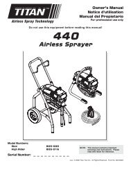
Parts ListMain Assembly1231314415165171819678149101112Item Part # Description quantity1 0558302 Motor cover...............................................12 0551440 Screw........................................................43 9800308 Screw........................................................44 ---------- Motor assembly.........................................15 0551526 Left leg assembly (stand only)..................16 0551553 Pail hook (upright cart only)7 763-552 Washer (upright cart only).........................28 710-033 Screw (upright cart only)...........................29 730-334 Hose clip (upright cart only)......................110 705-054 Siphon tube (upright cart only)..................111 0551556 Return hose (upright cart only).................112 710-046 Inlet screen (upright cart only) .................1Item Part # Description quantity13 ---------- Gear box assembly...................................114 0509550 Screw (stand)............................................40509550 Screw (upright cart)765-091 Screw (low boy)15 0551524 Right leg assembly (stand only)................116 0552754 Fluid section assembly(stand and low boy cart)............................10552762 Fluid section assembly (upright cart)17 704-117 Screw........................................................218 805-257A Suction set assembly(stand and low boy cart)............................119 0327226 Return hose clamp ...................................118 © Titan Tool Inc. All rights reserved.
Motor AssemblyNOTE: all electrical work shouldbe performed by a Titanauthorized service center.1234567Item Part # Description quantity1 0551540 Motor assembly (includes items 2–7and items 25, 29, and 30 in theGear Box Assembly parts list)...................12 770-099 Tie wrap....................................................13 704-206 Capacitor...................................................1Suction Set Assembly1Item Part # Description quantity4 704-285A Fan shroud................................................25 9802891 Screw........................................................26 704-250 Fan............................................................17 9804916 Fan screw..................................................10508645 Motor Brush KitLabelsPart # Description0552720 Logo label, front0552722 Logo label, left0552722 Logo label, right0551485 Warning label, explosion/injection0295805 Shock hazard label0507856 PRIME/SPRAY label34652Item Part # Description quantity1 0551705 Siphon tube assembly(includes items 1-7)...................................12 0551707 Return hose..............................................13 0279459 Hose clip...................................................14 700-805 Inlet screen................................................15 9871105 O-ring........................................................26 9822526 Retaining ring............................................17 9850638 Tie wrap....................................................2704-109 O-ring (for hot solvents, optional)© Titan Tool Inc. All rights reserved. 197
Gear Box Assembly451263789NOTE: all electrical work shouldbe performed by a Titanauthorized service center.10111217161819201321221415162320 © Titan Tool Inc. All rights reserved.
Item Part # Description quantity1 700-139 Screw........................................................42 0558301 Front cover................................................13 0551541 Slider assembly.........................................14 0508572 Crankshaft/gear assembly........................15 704-174 Thrust washer...........................................16 704-176 Second stage gear....................................17 0509219 Screw........................................................18 700-771 Pressure control knob...............................19 0551522 Knob housing............................................110 02712 Knob spring...............................................111 9822522 Washer......................................................112 806-032 Plunger......................................................113 800-741 Power cord assembly (stand)...................1806-213 Power cord assembly(low boy and upright cart)Item Part # Description quantity14 9800340 Ground screw............................................115 0551112 Transducer assembly (includes o-ring).....116 704-211A Circuit breaker...........................................117 9850936 ON/OFF switch..........................................118 03662 Microswitch insulator.................................119 0295490 Microswitch...............................................120 9800604 Screw........................................................221 704-281 Port plug....................................................122 700-139 Screw........................................................423 0523527 Heat sink / relay assembly........................10551520 Mechanical control assembly(includes items 9–12)Stand AssemblyUpright Cart Assembly (P/N 0551110)1237891234456105Item Part # Description quantity1 700-761 Cord wrap..................................................12 9885546 Plug...........................................................43 0551526 Left leg assembly(includes items 1, 2, and 7).......................14 704-244 Clip assembly............................................15 0551434 Screw........................................................16 700-1041 Drip cup.....................................................17 700-069 Screw........................................................28 226-001 Nut.............................................................19 0551524 Right leg assembly(includes items 2, 4, 5, 6, 8, and 10)10 9805230 Screw........................................................1Item Part # Description quantity1 0551660 Cart weldment (includes item 5)...............12 9890104 Cap............................................................23 0294534 Spacer.......................................................44 0278373 Wheel........................................................25 9885546 Plug...........................................................4© Titan Tool Inc. All rights reserved. 21
Fluid Section Assembly(Stand and Low Boy Cart P/N 0552754)(Upright Cart P/N 0552762)1234567Install upper packingwith raised lip andO-ring facing down.Raised LipO-Ring2223242526Item Part # Description quantity1 730-508 Retainer nut..............................................12 700-587 Piston guide..............................................13 ------- Upper packing assembly...........................14 806-091 Spacer.......................................................15 0551531 Pump manifold..........................................16 227-006 Outlet fitting, 1/4”.......................................17 0507690 PRIME/SPRAY valve assembly ...............18 ------- Lower packing assembly...........................29 704-551A Piston rod..................................................110 704-557 Outlet valve cage......................................111 704-612 Crush washer............................................112 50164 Outlet valve ball........................................113 704-558 Outlet valve seat.......................................114 13481 Outlet valve retainer..................................115 704-289 Piston bushing..........................................116 700-821 Nylon washer............................................117 704-703 Inlet valve cage.........................................118 762-145 Inlet valve ball...........................................119 762-137 Inlet valve seat..........................................120 762-058 O-ring, Teflon............................................121 704-054 Inlet valve housing (stand and low boy cart)..1730-511 Inlet valve housing (upright cart)22 0551532 Filter assembly (includes items 23–25).....123 0516775 Filter housing............................................124 581-060 Filter..........................................................125 560-038 Filter seal...................................................126 193-200 Fitting, 1/8 NPT x 1/4 barb hose(upright cart)..............................................19885612 Fitting, 1/8 NPT x 3/8 barb hose(stand and low boy cart)............................127 704-552A Piston assembly (includes items 9–13).....18Raised LipO-Ring0552951 Repacking kit (includes items 2–4, 810–12, 16, 18, and 20)0551509 Lower seal insertion tool910111213Install lower packingswith raised lip andO-ring facing up.27141516171819202122 © Titan Tool Inc. All rights reserved.
Low Boy Cart Assembly910111213123456738Item Part # Description quantity1 0551608 Cart weldment (includes items 6 and 14)..12 704-291 Roll pin......................................................23 0294534 Wheel spacer............................................44 0270394 Wheel........................................................25 9890104 Cap............................................................26 9885546 Plug...........................................................27 0295615 Lock nut.....................................................28 9805230 Screw........................................................19 773-918 Screw........................................................210 0551551 Mounting bracket, left................................111 0551552 Mounting bracket, right.............................1Electrical Schematic1415161718Item Part # Description quantity12 856-921 Screw........................................................413 856-002 Washer......................................................414 806-033 Plug...........................................................215 590-506 Handle washer..........................................216 590-508 Roll pin......................................................217 9841504 Snap button...............................................218 590-504 Sleeve.......................................................219 0551609 Handle asssembly(includes items 12, 13, and 15–18............120 700-1041 Drip cup.....................................................1NOTE: all electrical work should be performed bya Titan authorized service center.1920BlackPower cordBlackWhiteWH6WH1WH4BlueWhiteGreen / yellowBlackWH5RedWH2WH7BluePressureswitchSwitchF12FF34FWhiteFFCircuitbreakerMMBFFBRedRed+ +MotorMB FBCapacitorsBlackBlackFMFMFM© Titan Tool Inc. All rights reserved. 23
WarrantyTitan Tool, Inc., (“Titan”) warrants that at the time of delivery to the original purchaser for use (“End User”), the equipment coveredby this warranty is free from defects in material and workmanship. With the exception of any special, limited, or extended warrantypublished by Titan, Titan’s obligation under this warranty is limited to replacing or repairing without charge those parts which, to Titan’sreasonable satisfaction, are shown to be defective within twelve (12) months after sale to the End User. This warranty applies onlywhen the unit is installed and operated in accordance with the recommendations and instructions of Titan.This warranty does not apply in the case of damage or wear caused by abrasion, corrosion or misuse, negligence, accident, faultyinstallation, substitution of non-Titan component parts, or tampering with the unit in a manner to impair normal operation.Defective parts are to be returned to an authorized Titan sales/service outlet. All transportation charges, including return to thefactory, if necessary, are to be borne and prepaid by the End User. Repaired or replaced equipment will be returned to the End Usertransportation prepaid.THERE IS NO OTHER EXPRESS WARRANTY. TITAN HEREBY DISCLAIMS ANY AND ALL IMPLIED WARRANTIES INCLUDING,BUT NOT LIMITED TO, THOSE OF MERCHANTABILITY AND FITNESS FOR A PARTICULAR PURPOSE, TO THE EXTENTPERMITTED BY LAW. THE DURATION OF ANY IMPLIED WARRANTIES WHICH CANNOT BE DISCLAIMED IS LIMITED TOTHE TIME PERIOD SPECIFIED IN THE EXPRESS WARRANTY. IN NO CASE SHALL TITAN LIABILITY EXCEED THE AMOUNTOF THE PURCHASE PRICE. LIABILITY FOR CONSEQUENTIAL, INCIDENTAL OR SPECIAL DAMAGES UNDER ANY AND ALLWARRANTIES IS EXCLUDED TO THE EXTENT PERMITTED BY LAW.TITAN MAKES NO WARRANTY AND DISCLAIMS ALL IMPLIED WARRANTIES OF MERCHANTABILITY AND FITNESS FORA PARTICULAR PURPOSE WITH RESPECT TO ACCESSORIES, EQUIPMENT, MATERIALS OR COMPONENTS SOLD BUTNOT MANUFACTURED BY TITAN. THOSE ITEMS SOLD, BUT NOT MANUFACTURED BY TITAN (SUCH AS GAS ENGINES,SWITCHES, HOSES, ETC.) ARE SUBJECT TO THE WARRANTY, IF ANY, OF THEIR MANUFACTURER. TITAN WILL PROVIDETHE PURCHASER WITH REASONABLE ASSISTANCE IN MAKING ANY CLAIM FOR BREACH OF THESE WARRANTIES.Material Safety Data Sheets (MSDS) are available on Titan’s website or by calling Customer Service.PatentsThese products are covered by one or more of the following U.S. patents:6,031,352 5,848,566 5,769,321 5,725,364 5,671,656 5,435,697 5,228,8425,346,037 5,252,210 5,217,238 5,192,425 4,908,538 4,768,929 4,744,571D384,676 6,179,222 5,934,883 4,723,892United States Sales & ServicePhone: 1-800-526-5362Fax: 1-800-528-48261770 Fernbrook LaneMinneapolis, MN 55447www.titantool.comCanadian BranchPhone:Fax:1-800-565-86651-800-856-8496200 Trowers Road, Unit 7BWoodbridge, Ontario L4L 5Z8Phone:Fax:International1-201-337-12401-201-405-74491770 Fernbrook LaneMinneapolis, MN 5544724 © Titan Tool Inc. All rights reserved.