MVS-8000G Series DVS-9000 Series - WTS Broadcast
MVS-8000G Series DVS-9000 Series - WTS Broadcast
MVS-8000G Series DVS-9000 Series - WTS Broadcast

Create successful ePaper yourself
Turn your PDF publications into a flip-book with our unique Google optimized e-Paper software.
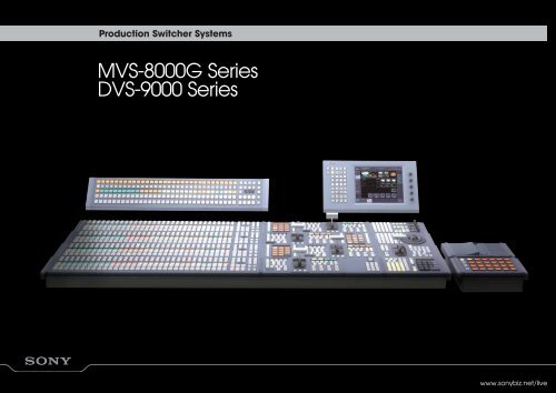
Production Switcher Systems<strong>MVS</strong>-<strong>8000G</strong> <strong>Series</strong><strong>DVS</strong>-<strong>9000</strong> <strong>Series</strong>www.sonybiz.net/live
The Perfect Answerto Creative <strong>Broadcast</strong>ing Demands
3IntroductionAs broadcasting becomes ever morecomplex, the systems used to supportcustomers' production needs have becomeincreasingly more flexible.In response to the growing demand for moresophisticated content, together with the challengespresented by High Definition and DTVagendas in live production operations, Sonyoffers the <strong>MVS</strong>-<strong>8000G</strong> and <strong>DVS</strong>-<strong>9000</strong> <strong>Series</strong> ofdigital live production switchers.The <strong>MVS</strong>-<strong>8000G</strong> inherits the same architectureas the highly acclaimed <strong>MVS</strong>-8000A <strong>Series</strong> andadds some powerful new features such asa Resizer function (internal 2D DME) and built-informat converter. The new <strong>MVS</strong>-<strong>8000G</strong> <strong>Series</strong> isavailable in Standard Definition (SD) configurationas standard and by an additionalsoftware purchase upgraded to full multi-formatconfiguration to suit HD production in line withoperational requirements.While the <strong>DVS</strong>-<strong>9000</strong> <strong>Series</strong> provides top-quality yetcost-effective SD programming, the <strong>MVS</strong>-<strong>8000G</strong><strong>Series</strong> offers full multi-format operation across avariety of SD and HD formats.The design philosophy behind both of theseswitcher systems has resulted from extensivecustomer feedback. The result is customisablecontrol panels with highly intelligible indicatorsand buttons, advanced networking with systemperipherals, integrated control and maintenance,powerful M/E functions and effects,complete system scalability and specialconsiderations for use in mixed PC and AV environments.Due to their common architecture, <strong>MVS</strong>-<strong>8000G</strong>and <strong>DVS</strong>-<strong>9000</strong> <strong>Series</strong> switchers also share thesame optional accessories, including controlpanels, remote panels and peripherals.Their system control structure and set-up/effectdata are also compatible, making it easy toestablish a mixed <strong>MVS</strong>-<strong>8000G</strong> and <strong>DVS</strong>-<strong>9000</strong><strong>Series</strong> environment providing simultaneous SDand HD production. What’s more, <strong>MVS</strong>-<strong>8000G</strong>and <strong>DVS</strong>-<strong>9000</strong> <strong>Series</strong> switchers can be furtherenhanced by the addition of two powerfulsoftware packages for editing and systemmanagement applications.With the <strong>MVS</strong>-<strong>8000G</strong> and <strong>DVS</strong>-<strong>9000</strong> <strong>Series</strong>,broadcasters and post-production facilitiesaround the world can realise high qualityproduction and strong return on investment.
4Flexibility for Today and Tomorrow<strong>MVS</strong>-<strong>8000G</strong> <strong>Series</strong> Multi-Format SwitchersThe <strong>MVS</strong>-<strong>8000G</strong> <strong>Series</strong> of production switchers areavailable in either Standard Definition (SD) or multiformatconfigurations. If they are initially supplied in anSD configuration, they can easily be upgraded to multiformat(SD/HD) configuration with the purchase ofadditional software (BZS-8500M/8510M/8520M/8530M).<strong>MVS</strong>-<strong>8000G</strong> <strong>Series</strong> switchers can operate in any of thefollowing formats:Multi-Format 1080i/60, 59.94, 50Configuration 1080P/30, 29.97, 25, 24, 23.976720P/59.94, 50SD Configuration 480i/59.94576i/50<strong>DVS</strong>-<strong>9000</strong> <strong>Series</strong> StandardDefinition SwitchersThe <strong>DVS</strong>-<strong>9000</strong> <strong>Series</strong> of production switchers aredesigned exclusively for SD and offer 525/625 switchableoperation. The <strong>DVS</strong> <strong>Series</strong> uses the same advancedtechnology and cutting-edge architecture of the<strong>MVS</strong>-<strong>8000G</strong> <strong>Series</strong>, thus offering a similar level ofoperational convenience and system flexibility. Inaddition, the system-control structure and set-up/effectdata are compatible with <strong>MVS</strong>-<strong>8000G</strong> <strong>Series</strong>, enablingthe user to configure a mixed <strong>DVS</strong>/<strong>MVS</strong> environment orinterchange effects between the two systems.Built-in Format ConverterOne of the unique and most powerful features of the<strong>MVS</strong>-<strong>8000G</strong> <strong>Series</strong> is the use of the optional MKS-8450Gformat converter board. This option provides up anddown-conversion between HD (1080i and 720P) and SD(480i and 576i) and cross-conversion between 1080i and720P at both inputs and outputs. By adding a singleformat converter board, conversion for eight inputs andtwo outputs is possible. Adding another board providesan additional eight input converters.Furthermore, when the MKS-8160G 24-output board set*is installed, two more format-conversion outputs areprovided.An <strong>MVS</strong>-<strong>8000G</strong> <strong>Series</strong> switcher can therefore beconfigured to seemlessly handle both SD and HD sourcesand provide independent SD and HD outputs, thusminimising system costs and complexity.* The <strong>MVS</strong>-<strong>8000G</strong>SF cannot accept the optional MKS-8160G Board.Example of format conversionScalable Processor ConfigurationsBoth the <strong>MVS</strong>-<strong>8000G</strong> and <strong>DVS</strong>-<strong>9000</strong> <strong>Series</strong> processors canbe configured to suit the exact requirements of eachparticular user in terms of number of I/O, number of M/Ebanks and which processing options are supplied.Another great benefit is that these switchers canbe upgraded as user needs grow, simply by installingthe appropriate option board.The <strong>MVS</strong> and <strong>DVS</strong> <strong>Series</strong> both offer the choice of a full orcompact sized processor, depending on user needs andscale of operation. Full-size <strong>MVS</strong>-<strong>8000G</strong> and <strong>DVS</strong>-<strong>9000</strong>processors can be configured for 2-, 2.5-, 3-, 3.5-, or 4-M/Eoperation and can accept up to 80 inputs, 48 assignableoutputs and 8 monitor outputs – enough for the largest ofprogramme requirements.The compact sized <strong>MVS</strong>-<strong>8000G</strong>SF and <strong>DVS</strong>-<strong>9000</strong>SFprocessors can be configured for 1-, 1.5-, 2-, or 2.5- M/Eoperation with up to 34 inputs and 24 outputs.The optional half M/E (simple P/P) software (BZS-8250)adds simple mix/effect functionality including twokeyers, background and key transitions. This softwareupgrades any 1, 2, or 3 M/E switcher processor to 1.5, 2.5and 3.5 M/E, respectively.Irrespective of which processor is chosen and with theexception of the half M/E software signals, all outputs arefully assignable and can be used for programme,preview, key preview, clean or auxiliary bus signals.SD PROGRAMME<strong>MVS</strong>-<strong>8000G</strong>SD8 CH2 CHSDINPUTHD 720PUP-CONVERTERHD1080iDOWN-CONVERTERHD8 CH2 CHHD 1080iHD 1080iHD PROGRAMME
5FeaturesChoose your definitionSwitcher processors2 to4 M/E1 to2.5 M/EMulti-format<strong>MVS</strong>-<strong>8000G</strong>8U80 inputs and 48 outputs8 monitor outputsSupports up to 8 (external) DME channelsResizer (simple 2D DME) per every keyerUp to 16 channels Input Format ConverterUp to 4 channels Output Format Converter<strong>MVS</strong>-<strong>8000G</strong>SF4U34 inputs and 24 outputsSupports up to 4 (external) DME channelsResizer (simple 2D DME) per every keyerUp to 16 channels Input Format ConverterUp to 2 channels Output Format Converter<strong>DVS</strong>-<strong>9000</strong>8U80 inputs and 48 outputs8 monitor outputs4 DME channels<strong>DVS</strong>-<strong>9000</strong>SF4U34 inputs and 24 outputs4 DME channelsAny CCP-8000 and CCP-<strong>9000</strong> control panel can control any processorControl panelsCCP-8000 Customisable control panelsCCP-<strong>9000</strong> Compact control panelsSDTVCustomisable Control PanelThe <strong>MVS</strong>-<strong>8000G</strong> and <strong>DVS</strong>-<strong>9000</strong> <strong>Series</strong> share the samecontrol panels, which have been designed afterextensive operational feedback. Two control panellineups are available: the customizable CCP-8000 <strong>Series</strong>and the compact CCP-<strong>9000</strong> <strong>Series</strong>.The CCP-8000 <strong>Series</strong> incorporates a modular design inwhich each control panel starts as an empty chassis.Users can locate modules in the chassis according totheir personal layout preferences. The base chassis isoffered in various widths and depths to suit three sizes ofcrosspoint modules (16, 24, or 32 button), up to 4 M/Estrips and various ancillary modules. There are threechoices of transition and key control modules, coveringsimple to complex video-layering requirements andvarious other modules which can be supplied accordingto operational needs. A separate chassis can also besupplied with just a crosspoint and transition modulefitted for remote M/E operation.The compact CCP-<strong>9000</strong> series are available in 1 or 2 M/Econfigurations with 12 crosspoint buttons. These controlpanels are well suited for standalone use in small-scaleOB vehicles and edit suites, or in conjuction with a largerCCP-8000 panel for remote M/E control.3.5 or4 M/E2.5 or3 M/E1.5 or2 M/E1.5 or2 M/E1 M/E
6Comprehensive Control SystemNetworking FunctionsThe <strong>MVS</strong>-<strong>8000G</strong> and <strong>DVS</strong>-<strong>9000</strong> <strong>Series</strong> utilise sophisticatednetwork capabilities to allow for an extremely efficientand innovative style of operation. Two Ethernet-basednetworks are provided: the Control LAN and the DataLAN. The former is a dedicated network that allowsefficient resource sharing among <strong>MVS</strong>/<strong>DVS</strong> switcherprocessors and CCP <strong>Series</strong> control panels. Using thisnetwork, multiple control panels can simultaneouslyshare a single switcher processor on an M/E basis (forefficient multi-tasking). Conversely, a single controlpanel can simultaneously control multiple switcherprocessors to deliver the same programme in multipleformats. The latter network, the Data LAN, provides aconnection across the <strong>MVS</strong>/<strong>DVS</strong> <strong>Series</strong> to all keycomponents and Sony peripherals. This network is usedfor general switcher housekeeping control such a framememory transfer as well as remote administrative taskssuch as status monitoring, maintenance and facilitymanagement tasks. Keeping the real time controlseparate from the data LAN guarantees that there isalways bandwith available to suit the on-air switcheroperation. This second network can also extend, via agateway, across an office LAN or WAN and even reachout over the Internet for remote switcher control.System Management SoftwareThe optional system management software running ona remote PC enables integrated management of allSony live-production products configured around andnetworked to <strong>MVS</strong>-<strong>8000G</strong>/<strong>DVS</strong>-<strong>9000</strong> <strong>Series</strong> switchers.This function enables centralised control of <strong>MVS</strong>/<strong>DVS</strong><strong>Series</strong> switchers, PFV-SP <strong>Series</strong> signal processing units froma single user interface.This system allows remote set-up, maintenance andoperation of each device connected to the network, aswell as efficient file management of set-up, effect andimage data. In addition, remote control of the internalswitcher frame memory is possible, allowing a seconduser to view and manipulate stored images.Two types of system management software are available:server/client BZPS-8000 software and standaloneBZPS-8000L software. BZPS-8000* software is suitable forlarge-scale systems and allows up to 10 client PCs toaccess the switchers via the server PC connected to theData LAN. For smaller systems, where there is no need tointegrate into an office network, the BZPS-8000L (serverless) version is available. This software can be installed onjust a single client PC, which can then be connecteddirectly to the Data LAN, allowing for simple and costeffectivesystem integration. In addition to the BZPS-8000system management software BZPS-8001 software is alsoavailable giving users complete remote control of allswitcher functions via the remote client PC.* A single BZPS-8000 Software license allows for installation on one server PC andmultiple client PCs (see actual licenses for details).Efficient Control SystemFacility (User) LAN CONTROL PANEL 1SYSTEMMANAGERCONTROLDATAS-BUSSWITCHERPROCESSOR<strong>MVS</strong>-<strong>8000G</strong>CCP-8000DME PROCESSORMVE-8000AMVE-<strong>9000</strong>CONTROL PANEL 2CCP-<strong>9000</strong>Powerful Device ControlExternal VTRs, DDRs and P-bus devices can all becontrolled directly from the <strong>MVS</strong>-<strong>8000G</strong>/<strong>DVS</strong>-<strong>9000</strong> <strong>Series</strong>control panel, giving the operator the ability to manuallycue up any material. This data can then be stored aspart of a switcher timeline which can be subsequentlyrecalled as required. When integrating a VDCPcontrolleddisk recorder, clip management is provided,allowing different server clips to be recalled and playedback as part of a switcher timeline.The new MKS-8036A Device Control Module providesdevice controls such as a jog/shuttle dial, controlbuttons and timecode displays. This gives operatorsquick, intuitive and familiar control of connected VTRsand disk recorders. Playback control of internal framememory clips is also possible with this module.The remote machine interface is provided by either theMKS-8700 or MKS-2700 device control units. Each unitprovides connectivity to the external devices viaRS-422A, P-bus, or GPI. The MKS-8700 can have up to 30RS-422A control ports or up to 270 GPIs, while theMKS-2700 has 6 RS-422A ports and 34 GPIs as standard.DEVICE CONTROL UNITMKS-8700MKS-2700EDITORKEYBOARDMKS-8050MKS-2050UNIVERSALCONTROL PANELUCP-8060IF PROCESSORSPFV-SP3300PFV-SP3100AUX BUS PANELSMKS-8080MKS-8082ROUTING SWITCHERHDS-X5800IXS-6700IXS-6600
7Plug-in Editing Control SoftwareTo further enhance the machine control interface anon-linear editing system can easily be added to theswitcher system. The plug-in editor software (BZS-8050)utilises the in-built machine control functions to addpowerful linear editing capabilities to any <strong>MVS</strong>-<strong>8000G</strong>,<strong>DVS</strong>-<strong>9000</strong>, or MFS-2000 <strong>Series</strong> switcher.This unique solution offers a similar level of functionality tothe popular BVE-2000 editor, plus some key functionsavailable on the BVE-9100 editor. Furthermore, thissoftware provides a variety of beneficial new featuresthat include direct keys for source selection and directdevice control of the connected VTRs. Two types ofediting keyboards are available to suit individualoperational preferences (MKS-8050 and MKS-2050).These keyboards make the editing control softwaresuitable for operations ranging from small-scale editingsystems to large-scale post-production mastering.A character superimpose function including Timecodeand Recorder/Player status is also available from the editO/P of the switcher (<strong>MVS</strong>-<strong>8000G</strong>/GSF only).With the addition of this editing capability, Sonyswitchers are truly maximised for effectiveness inbroadcast stations and post-production facilities.Combining Sony Switcherswith Sony Routing SystemsThe integration of <strong>MVS</strong>-<strong>8000G</strong> and <strong>DVS</strong>-<strong>9000</strong> <strong>Series</strong>switchers with S-bus-controlled routers, such as IXS-6000<strong>Series</strong> routing systems, brings a number of great benefitssuch as two-way operational control, source nameexchange and tally management. Crosspoints of theIXS-6000 <strong>Series</strong> can be controlled via the AUX BUS modulepanel of the CCP-8000 <strong>Series</strong> control panel. These can thenbe memorised and recalled as a router snapshot ortimeline event.Intelligent Tally Functions<strong>MVS</strong>-<strong>8000G</strong>/<strong>DVS</strong>-<strong>9000</strong> <strong>Series</strong> switchers provide anintelligent and multi-functional tally system, whichseamlessly integrates the switcher and router tallyfunctions.Multiple on-air and recording tallies can easily beprogrammed on the switcher system and even the mostcomplex of tally requirements can be easilyaccommodated. Tally information is provided eitheras standard (RS-422A) serial tally data directly fromthe control panels or via GPI connections on either theMKS-8700 or MKS-2700 device control units.
8Expand Your CreativityCreative M/E FunctionalityThe <strong>MVS</strong>-<strong>8000G</strong>/<strong>DVS</strong>-<strong>9000</strong> <strong>Series</strong> inherits many of thefeatures of the well-proven <strong>DVS</strong>-7000 <strong>Series</strong>, but withsignificant enhancements. Each M/E on the <strong>MVS</strong>-<strong>8000G</strong>/<strong>DVS</strong>-<strong>9000</strong> is equipped with four keyers, allowingsophisticated layering from a single M/E. Separate fromthe main fader, each keyer has its own auto-transitioncontrols, which allow users to insert or remove keys on anindividual basis with independent wipes, DME wipes anddissolves.For further flexibility, each keyer in every M/E also offerschroma keying and colour vector keying, eliminatingrestrictions of selectable key types. These fully featuredM/Es allow total interoperability of effects on all M/Es.Market-acclaimed Finekey technology allows fineadjustment of key position and border widths on asubpixel level within the range of 8H on the <strong>MVS</strong>-<strong>8000G</strong>and <strong>DVS</strong>-<strong>9000</strong> <strong>Series</strong>. Sony’s unique processed key modeand DME-link function are also provided, with additionalpower and convenience. Up to four video signalscomposed in the background can be processedthrough the DME within a single keyer, allowing for evengreater operational flexibility.Each M/E bus also includes an enhanced wipe patterngenerator with over 100 preset patterns, sub wipegenerator, transition PVW ability, individual mattgenerators and two utility busses for video in borders andeffects. With all these facilities included, on every M/E asstandard, the programme O/P is only limited by thecreational ability of the individual operator.Independent M/E ArchitectureEach M/E of the <strong>MVS</strong>-<strong>8000G</strong> and <strong>DVS</strong>-<strong>9000</strong> <strong>Series</strong>switchers, including the PGM/PST bus, are equipped withpowerful functions to customise the operation forindividual events. Snapshot and keyframe settings,various set-ups such as crosspoint assignments, 4:3/16:9modes and bus toggle on/off can all be independentlyset for each M/E. This architecture allows the user toefficiently programme the <strong>MVS</strong>-<strong>8000G</strong>/<strong>DVS</strong>-<strong>9000</strong> systemto suit the operation required.Multi-Programme ModeMulti-Programme mode, available on each M/E of the<strong>MVS</strong>-<strong>8000G</strong>/<strong>DVS</strong>-<strong>9000</strong>, enables four independent PGMoutputs to be generated inside each M/E bus. Eachoutput can contain any combination of the four M/Ekeyers over either the main M/E PGM, or a utility busbackground signal. This allows the user to performregional versioning of the same programme, without theneed to purchase an external keyer (Fig.1).Multi-Programme 2* mode, which is an extendedfunction of Multi-Programme mode, is also beneficial forexpanding the use of the system mix effects banks.This function allows one M/E to be separated into twosections – a main and a sub M/E – each half having theirown background transition generator. Keyers can beinserted into both the main and sub programmes asrequired and as shown below. (Fig 2) This functionenables the user to create two completely independentprogrammes within a single M/E.BACKGROUND ABACKGROUND BBACKGROUND AFor Multiple Language applicationsProgramme Out 1Programme Out 2KEY 1KEY 2KEY 3KEY 1KEY 2Fig 1The two M/E banks can then either be layered aboveeach other or split onto two separate rows on theswitcher control panel.This is convenient especially when simultaneouslybroadcasting sports such as baseball and football fortwo different destinations (areas of home and awayteams for example). With this mode, one operator cancreate two independent programmes from a singlecontrol panel. (Fig 3)* BZS-8200 Multi-Programme 2 Software is required. This function is only availableon <strong>MVS</strong>-8000A/G and <strong>MVS</strong>-8000ASF/GSF systems.Multi-ProgrammeBKGDABKGDBUTIL.2BKGDABKGDBUTIL.2(PGM)UTIL.3(PST)BKGDTRANSMulti-Programme 2BKGDTRANSBKGDTRANSProgramme for a home teamKey1Key2 Key3 Key4Key1 Key2 Key3 Key4PGM1PGM2MAINPGMSUBPGMUTIL.3(PST)BKGD BFig 2 Multi-Programme Mode Block Diagramme ExampleKEY1 KEY2KEY3BKGDABKGDBKEY1 KEY2BKGDABKGDB KEY4KEY1 KEY2KEY3BKGDABKGDBKEY2UTIL.2(PGM)KEY4BACKGROUND BKEY 4Programme for an away teamFig 3 “Home and Away” OperationSide flag
9Resizer FunctionThe <strong>MVS</strong>-<strong>8000G</strong>/<strong>8000G</strong>SF includes a useful resizerfunction that gives simple 2D DME picture manipulationwith adjustable parameters such as size, position, andaspect to every keyer. This can be utilised for picture-inpictureeffects and DME wipe transitions. A varietyof effects such as drop shadow, mosaic, and blur canbe applied to resized images. All these effects can becreated without the use of an external DME, bringinggreat advantages for both simple operations andminimized system cost. Being an M/E resource the resizerdata is also memorised as part of a switcher snapshot ortimeline event.Side Flags Function *This standard feature of the <strong>MVS</strong>-<strong>8000G</strong> series switcherallows a 4:3 source to automatically form a 16:9 pictureby adding desired graphics to both sides to the originalimage. This is convenient when using 4:3 material in a16:9 production. When selecting the 4:3 source side-flagscan be auomatically selected and a 16:9 imagecreated using dedicated hardware that does notcompromise system functionality, in other words withoutthe use of any keyer inside the M/E bus. In addition, cropmode is provided when 4:3 pictures are used in DMEwipe operations. This mode allows the margins between16:9 and 4:3 pictures to be cropped if desired. This isuseful for picture-in-picture effects where you do notrequire the addition of the side flags.* This function is currently not supported in SD mode.Enhanced Frame Memory SystemThe <strong>MVS</strong>-<strong>8000G</strong>/<strong>DVS</strong>-<strong>9000</strong> <strong>Series</strong> provide a highcapacityframe memory system that enables videoframes to be captured and stored either as still imagesor as clip sequences. With the <strong>DVS</strong>-<strong>9000</strong> <strong>Series</strong> up to444 images can be stored in the internal memory.With the <strong>MVS</strong>-<strong>8000G</strong> <strong>Series</strong> either one or two optionalMKS-8442G frame memory boards can be supplied andup to <strong>9000</strong> images can be stored. (exact storagecapacity is dependant on the operating standard and isas detailed in the chart below). The frame memorysystem allows instant recall of any stored image or cliponto any one (or more) of the eight outputs as either avideo or key signal. A thumbnail PVW of all storedimages and clips is displayed on the menu system and aclip viewer is also provided allowing you to scroll throughany individual clip.Furthermore the <strong>MVS</strong>-<strong>8000G</strong> <strong>Series</strong> has an interface forexternal HDD which allows for quick and easy back-upand recall of all frame memory data and theopportunity to easily transport images between differentswitcher systems. It is also possible to import TIFF/TGA/BMPimage files directly from the switcher control panel.Total frame storage capacity (approximate):Formats 1 x MKS-8442G 2 x MKS-8442G(still images)1080i 1000 2000 (1000)720P 2000 4000 (2000)480i 5000 10000 (5000)576i 4500 <strong>9000</strong> (4500)Easy and Efficient OperationAll <strong>MVS</strong>-<strong>8000G</strong>/<strong>DVS</strong>-<strong>9000</strong> <strong>Series</strong> switchers include a largecolour touch-screen menu for efficient and intuitivesystem control. Through this menu system all operationalparameters can easily be adjusted. The menu alsoincludes an interactive M/E status display giving the userfull information about the current M/E. Menu favouritescan be set-up and recalled at the touch of a button andhelp is never far away as the system also includes aviewable operational manual.The control panel surface includes three colour LCDsource name displays and optional flexipad andshotbox memory recall panels to which preset patternicons or text can be imported and displayed.Programmable MacrosHaving a dedicated button for each function on the<strong>MVS</strong>-<strong>8000G</strong>/<strong>DVS</strong>-<strong>9000</strong> <strong>Series</strong> is handy, but the macrosystem allows users to take operational convenience astep further. Any operational key sequence can berecorded and stored as a macro. This is very useful incue-ing up a VTR whenever the source VTR button ispressed or automatically turning on a key whenever acertain camera is selected for example. It will also bepossible to store menu set-up commands as macroevents in a future software revision.Using the FlexiPad module, or the 10-key pad module,users can simply record operational sequences, thenstore and assign them to any desired button (or evenfader arm). Macros are extremely useful in liveenvironments when time is critical and there is notolerance for making operational mistakes. Onceprogrammed, macros can be edited either directly fromthe control panel or by using the text based editor onthe touch-screen menu display.In the case when two MKS-8442G cards are installed the second card is used foradditional clip storage only.
0Explore your ImaginationSophisticated Digital Multi-Effects (DME)Depending on the application there are a number ofexternal DME processors available to enhanceyour operation. Up to eight channels of fully featurednon-linear DME can be specified for either the<strong>MVS</strong>-<strong>8000G</strong> or <strong>DVS</strong>-<strong>9000</strong> systems. Each channel alsoincludes a separate key channel and the DME caneither be connected via a dedicated video interface,which does not consume primary switcher I/Ps or O/Ps orvia a coaxial video connection.Being an integrated resource the DME is allocated asrequired, is freely assignable across the whole switcherand can be utilised for either DME wipe transitions or keyeffects. Each channel can manipulate a 2D image in 3Dspace and provides a variety of image manipulationeffects. As well as supporting the standard range of DMEeffects each channel also includes global axis controland a combiner function. By assigning multiple channelsto a single keyer and using the combiner's easy brickmode a slab can be produced at the touch of a button.For <strong>MVS</strong>-<strong>8000G</strong>/GSF <strong>Series</strong> switchersIn addition to the standard internal key re-size enginesup to eight channels of integrated full feature DME canbe fitted when two DME processors are connected tothe <strong>MVS</strong>-<strong>8000G</strong>*. Two processor options are available tosuit the production requirements:* Only four channels are supported on the <strong>MVS</strong>-<strong>8000G</strong>SFMVE-8000AThe 2RU MVE-8000A DME processor supports a standardrange of features including non-linear effects, lighting,glow and film mode.MVE-<strong>9000</strong>The larger (4RU) MVE-<strong>9000</strong> DME processor is alsoavailable and offers a greater range of effects than theMVE-8000A. In addition to the feature sets provided bythe MVE-8000A, it delivers enhanced picture quality anda wider assortment of features for the creation of strikingspecial effects in live events and post-production.A rich variety of effects are provided, such as DepthCombine, Dim/Fade, Wipe Crop, Art Edge, Key Border,Spot Lighting, Texture Lighting, Flex Shadow and Wind –as well as other effects available on the MVE-8000A.For <strong>DVS</strong>-<strong>9000</strong> <strong>Series</strong> SwitcherThe <strong>DVS</strong>-<strong>9000</strong> <strong>Series</strong> benefits from the optional internalfour channel effect card (BKDS-9470), however, forsystems requiring up to eight channels of DME effects,either the MVE-8000A or MVE-<strong>9000</strong> system can beadditionally specified and would be interfaced via theuse of BNC SDI connectors.BKDS-9470The internal BKDS-9470 DME board set offers fourchannels of non-linear digital effects. This DME boardcan perform linear and non-linear effects includingDigital SKETCH, Digital SPARKLE and up to four channelsof intersect combine. Each DME channel also providesexternal video input for use as the background orborder/trail source. The four SDI monitor outputs on theDME board allow monitoring of either the video withgraphic, the video without graphic, or the key. Also,powerful lighting effects can be added to non-linearand 3D-effect patterns, with easy set-up of colour andshape for the light source.Texture Lighting SoftwareOptional texture lighting software is supported for boththe MVE-<strong>9000</strong> and BKDS-9470 DME processors.This software adds a texture lighting function thatenables the user to map a texture pattern onto a DMEeffect using the spotlight function. The Real Lightingfunction can add realistic lighting to several non-lineareffect patterns. Up to four light sources are available perDME channel.
!¡System ConfigurationCentre Control Panel CCP-8000 <strong>Series</strong>MKS-8017A 32 XPT ModuleMKS-8020A Standard Transition ModuleMKS-8027A Compact Transition Right ModuleMKS-8018A 24 XPT ModuleMKS-8021A Simple Transition Right ModuleMKS-8028A Compact Transition Left ModuleMKS-8019A 16 XPT ModuleMKS-8021ASC Simple Transition Compact R ModuleMKS-8026A 10-Key PAD ModuleMKS-8013A 32 AUX BUS ModuleMKS-8022A Simple Transition Left ModuleMKS-8030A Key Frame ModuleMKS-8014A 24 AUX BUS ModuleMKS-8022ASC Simple Transition Compact L ModuleMKS-8031ATB Track Ball ModuleMKS-8015A 16 AUX BUS ModuleMKS-8023AB Compact Key Transition ModuleMKS-8031AJS Joystick Module
!System ConfigurationSophisticated Digital Multi-Effects (DME)Centre Control Panel CCP-<strong>9000</strong> <strong>Series</strong>MKS-8036ADevice Control ModuleMKS-8025MSMemory Stick /USB ModuleMKS-8011AMenu PanelMKS-9011A1 M/E Control PanelMKS-9012A2 M/E Control PanelMKS-8032ADSK Fader ModuleMKS-8024AFlexipad ModuleMKS-8041Blank Panel (1/2)Remote PanelMKS-8080AUX BUS Remote Panel *MKS-8033AUtility/Shot Box ModuleMKS-8034ADKDSK/FTB ModuleMKS-8040Blank Panel (1/3)UCP-8060Universal Control Panel *MKS-8082AUX BUS Remote Panel ** Rack-mount brackets for these panels areincluded.Plug-in EditorSystem ManagementSoftwareMKS-8035AKey Control ModuleMKS-8034AFBFTB ModuleMKS-8042Blank Panel (1/6)MKS-8010A System Control UnitMKS-8050 Editing KeyboardBZPS-8000 System ManagementSoftwareBZPS-8000L System Management Software(Standalone type)BZPS-8001 Switcher Set-up SoftwareBZPS-8002 PFV-SP Set-up SoftwareHK-PSU02 Backup Power Supply UnitSWC-5002/5005/5010 Panel Cable (2/5/10 m)MKS-8075A Extension AdaptorMKS-8076 Memory Card USB AdaptorMKS-2050 Editing KeyboardBZS-8050 Editing Control Software
1559161017 133 1850 3417 133 1850 34815191325114!£Switcher ProcessorsDME ProcessorsRear PanelsThe figures show the rear panels in which optional boards are installed.MULTI-FORMAT SWITCHERPROCESSORPRODUCTION SWITCHERPROCESSORMVE-8000A Multi-Format DMEProcessorMKE-8020A <strong>MVS</strong> Interface BoardMKE-8021A Input/Output Board (for SDI)MKE-8040A Effects Board (2 channel)<strong>MVS</strong>-<strong>8000G</strong>SF(Full option)<strong>MVS</strong>-<strong>8000G</strong><strong>DVS</strong>-<strong>9000</strong>HK-PSU-02 Power Supply Unit<strong>MVS</strong>-<strong>8000G</strong>(Full option)<strong>MVS</strong>-<strong>8000G</strong>SF<strong>DVS</strong>-<strong>9000</strong>SFMVE-<strong>9000</strong> Multi-Format DME Processor17 Input Board MKS-8110GAdditional 12 Input Board MKS-8111G *124 Output Board Set MKS-8160G *18 Monitor Output Board MKS-8161M *112 Output Board MKS-8162A *2Mix/Effect BoardMKS-8210GFrame Memory Board MKS-8442GFormat Converter Board MKS-8450GDME Interface Board MKS-8170G *1Simple PP SoftwareBZS-8250Multi Program 2 Software BZS-8200Colour Corrector Software BZS-8420 *3Switcher Upgrade Software BZS-8500M *1(Upgrade SD to Multi-format)For <strong>MVS</strong>-<strong>8000G</strong>Switcher Upgrade Software BZS-8510M *2(Upgrade SD to Multi-format)For <strong>MVS</strong>-<strong>8000G</strong>SFMix/Effect Upgrade Software BZS-8520M(Upgrade SD to Multi-format)Mix/Effect Upgrade Software BZS-8530M *1(Upgrade SD to Multi-format)Power Supply UnitHK-PSU04*1 For <strong>MVS</strong>-<strong>8000G</strong> only*2 For <strong>MVS</strong>-<strong>8000G</strong>SF only*3 Optional MKS-8442G board is required.17 Input Board MKS-8110 SDAdditional 12-Input Board MKS-8111 SD *424 Output Board Set BKDS-9160 *48 Monitor Output Board BKDS-9161 *412 Output Board BKDS-9162 *5Mix/Effect BoardBKDS-9210DME Board SetBKDS-9470Simple P/P Software BZS-9250Colour Corrector Software BZS-9420Texture Lighting Software BZS-9471Power Supply UnitHK-PSU04*4 For <strong>DVS</strong>-<strong>9000</strong> only*5 For <strong>DVS</strong>-<strong>9000</strong>SF onlyStandard configuration:The <strong>DVS</strong>-<strong>9000</strong> is supplied with one 17 inputboard, one 24 output board, two mix/effect board sets, one frame memoryboard set and two power supply units. The<strong>DVS</strong>-<strong>9000</strong>SF is supplied with one 17 inputboard, one 12 output board, one mix/effect board set, one frame memoryboard set and one power supply unit.MKE-9020M <strong>MVS</strong> Interface BoardMKE-9021M Input/Output BoardMKE-9040M Advanced Effects Board(1 channel)BZDM-9050 Texture Lighting SoftwareDevice Control UnitMKS-8700 Device Control UnitMKS-8701 Tally/GPI Output BoardMKS-8702 Serial Interface Board<strong>DVS</strong>-<strong>9000</strong>(Full option)MVE-8000A(with <strong>MVS</strong> InterfaceBoard MKE-8020A)MVE-<strong>9000</strong>(with Input/Output Board MKE-9021M)<strong>DVS</strong>-<strong>9000</strong>SF(Full option)MKS-8010AMKS-8700with Tall/GPI Output BoardMKS-8701 x 3Serial Interface BoardMKS-8702 x 2MKS-2700Standard configuration:The <strong>MVS</strong>-<strong>8000G</strong> is supplied with one 17 inputboard, one 24 output board, two mix/effect board sets and two power supplyunits. The <strong>MVS</strong>-<strong>8000G</strong>SF is supplied withone 17 input board, one 12 output board,one mix/effect board set, DME interfaceand one power supply unit.MKS-2700 Device Control UnitHK-PSU-01 Backup Power Supply UnitMKS-9011A/9012A
!¢SpecificationsGeneralPower requirementPower consumption<strong>MVS</strong>-<strong>8000G</strong><strong>MVS</strong>-<strong>8000G</strong>SF<strong>DVS</strong>-<strong>9000</strong><strong>DVS</strong>-<strong>9000</strong>SFCCP-8000 <strong>Series</strong>CCP-<strong>9000</strong> <strong>Series</strong>MVE-8000AMVE-<strong>9000</strong>MKS-8700MKS-2700Operating temperatureStorage temperatureOperating humidityDimensions (W x H x D)<strong>MVS</strong>-<strong>8000G</strong><strong>MVS</strong>-<strong>8000G</strong>SF<strong>DVS</strong>-<strong>9000</strong><strong>DVS</strong>-<strong>9000</strong>SFCCP-8000 <strong>Series</strong> Main PanelAuxiliary Bus PanelMenu PanelSystem Control UnitCCP-<strong>9000</strong> <strong>Series</strong> 1 M/E Control Panel2 M/E Control PanelMenu PanelMKS-8700MKS-2700MVE-8000AMVE-<strong>9000</strong>Memory Stick/USB AdaptorExtension AdaptorMass (Approx.)<strong>MVS</strong>-<strong>8000G</strong><strong>MVS</strong>-<strong>8000G</strong>SF<strong>DVS</strong>-<strong>9000</strong><strong>DVS</strong>-<strong>9000</strong>SFCCP-8000 <strong>Series</strong>CCP-<strong>9000</strong> <strong>Series</strong>Main PanelAuxiliary Bus PanelMenu PanelSystem Control UnitMain PanelMenu PanelMKS-8700MKS-2700MVE-8000AMVE-<strong>9000</strong>Memory Card/USB AdaptorExtension AdaptorAC 100 to 240 V, ± 10% 50/60 Hz12 to 5 A7 to 3 A8.6 to 4.2 A5.5 to 2.5 A2.5 to 1.1 A1.1 to 0.5 A2.5 to 1.0 A6.0 to 2.5 A1.4 to 0.8 A0.7 to 0.5 A5 °C to 40 °C (41 °F to 104 °F)-20 °C to +60 °C (-4 °F to +140 °F)10% to 90% (Non-condensing)482 x 354 x 520 mm (19 x 14 x 20 1/2 inches)482 x 176 x 520 mm (19 x 7 x 20 1/2 inches)482 x 354 x 520 mm (19 x 14 x 20 1/2 inches)482 x 176 x 520 mm (19 x 7 x 20 1/2 inches)4 M/E, 32-crosspoint buttons:1443 (with mount bracket) x 98.5 x 528 mm (56 7/8 x 4 x 20 7/8 inches)3 M/E, 24-crosspoint buttons:1291 (with mount bracket) x 98.5 x 528 mm (50 7/8 x 4 x 20 7/8 inches)2 M/E, 16-crosspoint buttons:1139 (with mount bracket) x 98.5 x 396 mm (44 7/8 x 4 x 15 5/8 inches)32-crosspoint buttons:782 (with mount bracket) x 132 x 80 mm (30 7/8 x 5 1/4 x 3 1/4 inches)24-crosspoint buttons:630 (with mount bracket) x 132 x 80 mm (24 7/8 x 5 1/4 x 3 1/4 inches)16-crosspoint buttons:478 (with mount bracket) x 132 x 80 mm (18 7/8 x 5 1/4 x 3 1/4 inches)424 x 220 x 46 mm (16 3/4 x 8 3/4 x 1 13/16 inches)482 x 43.6 x 520 mm (19 x 1 3/4 x 20 1/2 inches)440 x 175 x 385.3 mm (17 3/8 x 7 x 15 1/4 inches)440 x 186.6 x 442 mm (17 3/8 x 7 3/8 x 17 1/2 inches)424 x 220 x 46 mm (16 3/4 x 8 3/4 x 1 13/16 inches)482 x 132 x 520 mm (19 x 5 1/4 x 20 1/2 inches)440 x 43.6 x 520 mm (17 3/8 x 1 3/4 x 20 1/2 inches)440 x 87.5 x 520 mm (17 3/8 x 3 1/2 x 20 1/2 inches)482 x 194 x 520 mm (19 x 7 3/4 x 20 1/2 inches)263 (with mount bracket) x 132 x 78.5 mm (10 3/8 x 5 1/4 x 3 1/8 inches)263 (with mount bracket) x 132 x 78.5 mm (10 3/8 x 5 1/4 x 3 1/8 inches)49 kg (108 lb) (fully loaded)28 kg (61 lb 12 oz) (fully loaded)43 kg (94 lb 13 oz)25 kg (55 lb 8 oz)4 M/E, 32-crosspoint buttons: 30 kg (66 lb 2 oz)32-crosspoint buttons: 3.7 kg (8 lb 2 oz)2.2 kg (4 lb 13 oz)11.5 kg (25 lb 6 oz)2 M/E, 12-crosspoint buttons: 12.5 kg (27 lb 9 oz)1 M/E, 12-crosspoint buttons: 11.5 kg (25 lb 6 oz)2.2 kg (4 lb 13 oz)8 kg (39 lb 10 oz) (fully loaded)9.8 kg (21 lb 10 oz)16 kg (35 lb 4 oz) (fully loaded)27 kg (59 lb 8 oz) (fully loaded)1.2 kg (2 lb 10 oz) (with module)1.5 kg (3 lb 4 oz) (with module)Video inputs/outputs<strong>MVS</strong>-<strong>8000G</strong>/<strong>8000G</strong>SFPrimary inputsAssignable outputsMonitor outputsIntegrated DME I/O<strong>DVS</strong>-<strong>9000</strong>/<strong>9000</strong>SFPrimary inputsAssignable outputsMonitor outputsBuilt-in DMEExternal inputsMonitor outputsMVE-8000AMKE-8020AVideo inputs/Video outputs<strong>MVS</strong> interfaceMKE-8021AVideo inputsVideo/KeyVideo outputsVideo/KeyMonitor outputsMVE-<strong>9000</strong>MKE-9020MVideo inputs/Video outputs<strong>MVS</strong> interfaceMKE-9021MVideo inputsVideo/KeyVideo outputsVideo/KeyExt Video InMonitor outputs<strong>MVS</strong>-<strong>8000G</strong>: Max. 80/<strong>MVS</strong>-<strong>8000G</strong>SF: Max. 34, BNC x 1 eachSMPTE292M (HDTV), SMPTE259M-C (SDTV)<strong>MVS</strong>-<strong>8000G</strong>: Max. 48/<strong>MVS</strong>-<strong>8000G</strong>SF: Max. 24,OUT 1, 2, 13 to 16, 25, 26, 37 to 40: BNC x 2 eachOUT 3 to 12, 17 to 24, 27 to 36, 41 to 48, FC1 to 4: BNC x 1 eachSMPTE292M (HDTV), SMPTE259M-C (SDTV)<strong>MVS</strong>-<strong>8000G</strong>: Max. 8, BNC x 2 eachSMPTE292M (HDTV), SMPTE259M-C (SDTV)MDR 68-pin x 4 (inputs/outputs: 2 CH x 4), LVDS<strong>DVS</strong>-<strong>9000</strong>: Max. 80/<strong>DVS</strong>-<strong>9000</strong>SF: Max. 34, BNC x 1 eachSMPTE259M-C (SDTV)<strong>DVS</strong>-<strong>9000</strong>: Max. 48/<strong>DVS</strong>-<strong>9000</strong>SF: Max. 24,OUT 1 to 4, 13 to 16, 25 to 28, 37 to 40: BNC x 2 eachOUT 5 to 12, 17 to 24, 29 to 36, 41 to 48: BNC x 1 eachSMPTE259M-C (SDTV)<strong>DVS</strong>-<strong>9000</strong>: Max. 8, BNC x 2 eachSMPTE259M-C (SDTV)BNC x 4SMPTE259M-C (SDTV)BNC x 4SMPTE259M-C (SDTV)MDR 68-pin x 2 (inputs/outputs: 2 CH x 2), LVDSBNC x 8, SMPTE292M (HDTV), SMPTE259M-C (SDTV)BNC x 8, SMPTE292M (HDTV), SMPTE259M-C (SDTV)BNC x 4, SMPTE292M (HDTV), SMPTE259M-C (SDTV)MDR 68-pin x 2 (inputs/outputs: 2 CH x 2), LVDSBNC x 8, SMPTE292M (HDTV), SMPTE259M-C (SDTV)BNC x 8, SMPTE292M (HDTV), SMPTE259M-C (SDTV)BNC x 4, SMPTE292M (HDTV), SMPTE259M-C (SDTV)BNC x 4, SMPTE292M (HDTV), SMPTE259M-C (SDTV)Reference<strong>MVS</strong>-<strong>8000G</strong>/<strong>8000G</strong>SF, <strong>DVS</strong>-<strong>9000</strong>/<strong>9000</strong>SF, Device Control Unit, DME Processor, System Control UnitReference inputsBNC x 2, 75 Ω with loop-through outputHDTV systems: HD tri-level sync/SDTV analogue syncSDTV systems: Analogue black burst/analogue syncMVE-8000AReference intputsBNC x 2, 75 Ω with loop-through outputAnalogue black burst or HD tri-level syncMVE-<strong>9000</strong>Reference intputsBNC x 2, 75 Ω with loop-through outputAnalogue black burst or HD tri-level sync
!∞Control<strong>MVS</strong>-<strong>8000G</strong>/<strong>8000G</strong>SFControl LANRJ-45 x 1, 100BASE-TXData LANRJ-45 x 1, 100BASE-TXRemote 1 to 4D-sub 9-pin, RS-422ATerminalD-sub 9-pin, RS-232CGPI D-sub 25-pin, TTL level inputs x 8, relay contact outputs x 4,open collector outputs x 4FM DataRJ-45 x 1, 100BASE-TXFM Device Complies with IEEE 1394<strong>DVS</strong>-<strong>9000</strong>/<strong>9000</strong>SFControl LANRJ-45 x 1, 100BASE-TXData LANRJ-45 x 1, 100BASE-TXRemote 1 to 4D-sub 9-pin, RS-422ATerminalD-sub 9-pin, RS-232CGPI D-sub 25-pin, TTL level inputs x 8, relay contact outputs x 4,open collector outputs x 4Extension BNC x 1Built-in DMEControl LANRJ-45 x 1, 100BASE-TXData LANRJ-45 x 1, 100BASE-TXEditor 1 to 4D-sub 9-pin, RS-422AGPI D-sub 25-pin, TTL level inputs x 8, relay contact outputs x 4,open collector outputs x 4CCP-8000 <strong>Series</strong> (System Control Unit)Control LANRJ-45 x 1, 100BASE-TXData LANRJ-45 x 1, 100BASE-TXPeripheral LANRJ-45 x 1, 100BASE-TXGPI D-sub 25-pin, TTL level inputs x 8, relay contact outputs x 4,open collector outputs x 4REMOTEBNC x 1, S-BUSLTC input BNC x 1DeviceUSB-type AMain PanelD-sub 50-pinMenu PanelD-sub 50-pinExt Panel 1 to 3D-sub 50-pinEditorD-sub 15-pin, RS-422AControlCCP-<strong>9000</strong> <strong>Series</strong>Control LANRJ-45 x 1, 100BASE-TXData LANRJ-45 x 1, 100BASE-TXPeripheral LANRJ-45 x 1, 100BASE-TXGPI D-sub 25-pin, TTL level inputs x 8, relay contact outputs x 4,open collector outputs x 4REMOTEBNC x 1, S-BUSDeviceUSB-type AMain PanelD-sub 50-pinMenu PanelD-sub 50-pinExt PanelD-sub 50-pinMVE-8000A (DME Processor)Control LANRJ-45 x 1, 100BASE-TXData LANRJ-45 x 1, 100BASE-TXREMOTED-sub 9-pin x 4, RS-422AGPI D-sub 25-pin, TTL level inputs x 8, relay contact outputs x 4,open collector outputs x 4MVE-<strong>9000</strong> (DME Processor)Control LANRJ-45 x 1, 100BASE-TXData LANRJ-45 x 1, 100BASE-TXREMOTEGPID-sub 9-pin x 4, RS-422AD-sub 25-pin x 2, dry contact or open collector inputs x 16, relay contactoutputs x 8, open collector outputs x 8MKS-8700 (Device Control Unit)Peripheral LANRJ-45 x 1, 100BASE-TXSerial tally 1 to 2D-sub 9-pin, RS-422ATALLY/GPI inputsD-sub 37-pin x 3, TTL level inputs x 34 eachTALLY/GPI outputs *D-sub 37-pin, relay contact outputs 18ch, up to 270 ch in stepof 5 ch in a frameREMOTE *D-sub 9-pin, RS-422A, various protocols, up to 30 ports in stepsof 6 ports in a frameMKS-2700 (Device Control Unit)Peripheral LANRJ-45 x 1, 100BASE-TXTALLY/GPI inputs D-sub 37-pin x 1, TTL level inputs x 34TALLY/GPI outputsD-sub 37-pin x 2, TTL level inputs x 18 eachREMOTED-sub 9-pin x 6, RS-422A, various protocols* TALLY/GPI and REMOTE ports are alternatively installed. Mixed configuration of TALLY/GPI and REMOTEports is supported.Services from Sony: working with you, working for you.Recognising that every company and every challenge is unique,we offer a complete and comprehensive range of services allthe way through consulting, planning, financing, implementation,training, servicing, maintenance and support.Choose exactly what’s right for you, when and where you need it.Not all services are available in all countries. If you’d like to find out more about what wedo, who we do it for and how we do it, visit www.sonybiz.net or contact your local Sonyoffice.Sony Professional ServicesTailor-made design, installation and project management ofaudio-visual and IT (AV/IT) systems using skills developed over25 years of systems integration.Sony Financial ServicesInnovative and flexible finance solutions designed to meet budgetaryand financial requirements and constraints, enabling businesses toalways have the most current technology.Sony Training ServicesA range of off-the-shelf or customised training services from basicoperation through to high-level technical maintenance.Sony Support ServicesFully integrated and customised support for products and systemsthroughout their operational life, combining proactive and reactivetechnical services
© 2007 Sony Corporation. All rights reserved.Reproduction in whole or in part without the written permission is prohibited.Sony, Digital SKETCH, Digital SPARKLE, FlexiPad and Shot Box are trademarksof Sony Corporation. Features and specifications are subject to change without notice.All non-metric weights and measurements are approximate.