Operating manual - Rifox-Hans Richter GmbH
Operating manual - Rifox-Hans Richter GmbH
Operating manual - Rifox-Hans Richter GmbH

You also want an ePaper? Increase the reach of your titles
YUMPU automatically turns print PDFs into web optimized ePapers that Google loves.
<strong>Operating</strong> Manual<br />
for RIFOair Automatic Vent Valve<br />
Type: EF-8180 PN 16/25 DN 15-50 Housing: EN-JS 1049 (GGG-40.3)<br />
EF-8080-N / 8180-N PN 16/25 DN 15-50 Housing: SS 1.4581 / 1.4552<br />
EF-8281 PN 40 DN 15-50 Housing: C-Steel (P265GH/HII)<br />
EF-8012/8112 PN 16/25 DN 50/65 Housing: C-Steel (P265GH/HII)<br />
EF-8012-N / 8112-N PN 16/25 DN 50/65 Housing: SS 1.4571 / 1.4541<br />
EF-8018/8118 PN 16/25 DN 80/100 Housing: C-Steel(P265GH/HII)<br />
EF-8018-N/8118-N PN 16/25 DN 80/100 Housing: SS 1.4571 / 1.4541<br />
1.0 Safety Instructions<br />
1.1 Normal Usage:<br />
Any mishandle,interference into the construction and any deviation from the design and design data lead automatically to the expiry of<br />
the guarantee. The exhaust machine is intended at points of plant high filled with liquid to derive from air and gas . A deviating use is<br />
inadmissible. The manufacturer is not responsible for any damage resulting from it . The risk is borne by the user or operator. This is also<br />
valid incase of wrong assembly, usage and maintenance.<br />
1.2 Warning Instructions and Symbols<br />
• Endangerment to person by withdrawing operating medium with pressure,temperature and weight<br />
Negligence can lead to accidents<br />
Read carefully the instructions in this <strong>manual</strong><br />
The operator must keep the <strong>manual</strong> and other applicable guide books handy,while operating the system<br />
To be used by qualified personnel<br />
Each safety risk function is to be omitted<br />
2.0 General Description and Usage<br />
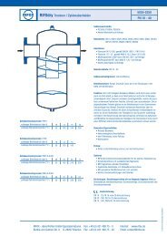
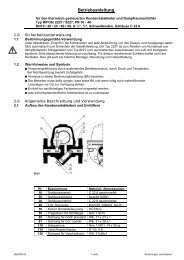
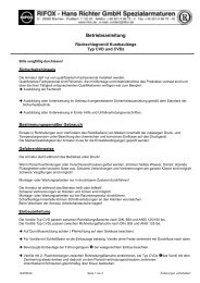
2.1 Assembly of the Exhaust Fan<br />
Fig. 1<br />
Type EF- 8180/8080-N / 8180-N<br />
Fig. 3<br />
Type EF-8012/8012-N,8112,8112-N<br />
Additional<br />
Equipment<br />
Fig. 2<br />
Additional<br />
Equipment<br />
Type EF-8281<br />
Type EF-8018,8018-N,8118,8118-N<br />
Additional<br />
Equipment<br />
Position 1 Bottom part of body Position 6 Plug<br />
Position 2 Housing gasket Position 7 Complete float control<br />
Position 3 Upper part of body Position 10 Carrying screw/ socket drawer<br />
Position 5 Housing screws Position 14 Plug<br />
03/2011 - Di 1<br />
Subject to Modifications<br />
Fig. 4
2.2 Label and Limitations of Use on the specification plate or body<br />
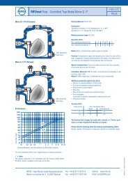
2.3 Functional range of the float control(PMO in bar g)<br />
Cross-section Cold water High<br />
temperature<br />
water<br />
Cross-section Cold water High temperature<br />
water<br />
ld 25 20 VIIIa 5 4<br />
lId 23 18 VIIIb 4,5 4<br />
IIa 40 32 20/190 12 12<br />
III 16 13 20/340 9 8<br />
IV 14 11 25/200 25 21<br />
V 2,8 2,5 25/400 23 18<br />
VI 25 16 30/550 5 5<br />
VIa 25 20 50/1100 5 5<br />
VII 23 16<br />
SQ / SK Special design after procedure data<br />
2.4 Function / Installation / Location<br />
The exhaust fan is over headed (Picture 1-4 installed over a short riser on high plant point (container/piping).A stop valve (preferably<br />
a ball valve) to be inserted into the riser to the exhaust fan<br />
Air and gases in the lower float position escape over the immersion nozzle on top of the open valve cross section outlet.With<br />
liquid,the float gauge is raised, the controller closes.<br />
As it is a mechanical valve end, even a small drop of leakage is unavoidable. If necessary and depending upon exposure through the<br />
operating medium a catch line is provided at the outlet<br />
3.0 Installation<br />
Support: When you type 8018 / 8118, DN 80/100, the weight of the ventilator/exhaust (115 kg) is taken over by a holder and a<br />
support, for example ,those involving the body of welded claws. By typing 8012/8112, the support can be avoided, if the riser is<br />
mounted sufficiently before the ventilator(Weight approx 45).<br />
Installation: In accordance with Figures 1 to 4 on a vertical riser on the system high point.<br />
Remove plastic cover from the inlet (a) and outlet (b)<br />
4.0 Start-up<br />
The pressure build-up and warming up of the case should not be done abruptly. If after the initial<br />
Start up, the leakages occur , the screws positioned 4/5/6 to<br />
be tightened if necessary, taking into account the torques mentioned. The tightening may only be done pressure free and followed till<br />
lukewarm body.<br />
5.0 Maintenance/Inspection<br />
5.1 Opening of the Ventilator and expansion of the float control<br />
The air vent must be depressurized. Accompanied, where appropriate, downstream of the trap safely shut off.<br />
The residual pressure in the body by releasing item (14) or (6) Drain to only a quarter turn.<br />
from size DN 40/50, a lifting device fastened to the flange pipes and gently lifted out of the pipeline.<br />
Body screws (5) unscrew on the cross. Detach bodyparts (1)<br />
5.2 Expansion of the float control in model EF-8080/8180 (Figure1)<br />
Loosen and unscre the mounting screw(10) by 1-2 turns.<br />
With a plastic hammer,strike mainly on the face of the mounting screw(10)<br />
This solves the float control of the seat cone.<br />
Unscrew the screw with the joint ring(20) and remove completely.<br />
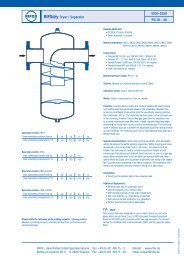
5.3 Removing the Float control in model EF-8281 (Figure2)<br />
The assembly thorn which can be supplied by us is screwed into 3 courses in the thread<br />
of the supporting body (Figure4 ). The float control of the conical seat driven with slight to<br />
moderate blown Hammer to the head of the pin.Float this.Lift.Then turn out the assembly<br />
pin and see the float control through lid opening.<br />
5.4 Expansion of the Float control in Model EF-8012/8112 (Figure3)<br />
Insertion of the main assembly to be supplied in the 2 slots in the support sleeve(Fig. 6)<br />
Loosen the support sleeve by anti clockwise turning left(3-4 courses).The float control of<br />
the conical seat driven with slight to moderate Hammer blown to the head of the pin.Float<br />
this.Then remove the support sleeve completely and remove the float control through lid<br />
opening.<br />
5.5 Removing the float control in Model EF-8018/8118 (Fig 4. And 7.)<br />
Succeeded with a mounting steel sheet or with an assembly.Utility which is plugged into<br />
the jack provided with two holding millings (10.)Through turning to the left (3-4 courses)<br />
the lockingbush is loosened in the supporting body.After some slight to moderate blow<br />
on the hammer to the assembly Utility(picture) triggers the float control of the conical seat<br />
while lifting as possible. Then remove the support sleeve completely and remove the float<br />
control through lid opening.<br />
Fig. 5<br />
Fig. 6<br />
Locking<br />
Bush<br />
Assembly<br />
thorn<br />
Supporting Body<br />
03/2011 - Di 2<br />
Subject to Modifications
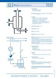
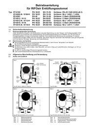
5.6 Disassembling and cleaning the Float control (Fig.8 and 9)<br />
1. After removing the split pin,(i) the rotary valve is pulled (j)simply by the page through the<br />
round hole in the float.<br />
2. Clean the parts in benzine cleaning solvent.<br />
3. Examine the rotary valve( j)on wear of the sealing edge. If required, support body (8)<br />
must be replaced with a rotary valve (j). An accurate leak test must be performed at<br />
RIFOX<br />
4. When assembling,make sure the notch in the rotary valve (j)at the centre mark in the<br />
supporting body(8)and showing the Splint(i)is being carefully used and spread.<br />
5. Check the upper rotary valve (j)is low-friction , i.e the float must <strong>manual</strong>ly move upwards<br />
and downwards easily.<br />
5.7 Installation of the control<br />
a) in Model EF-8080/8180 (Figure1.)<br />
The control is implemented in the conical valve seat with the support body. It should be<br />
ensured the float lies in middle of the housing body (1.). The carrying screw (10)with<br />
sealing ring (20.)is screwed and tightened in the thread of the supporting body with a<br />
moderate key. Tighten torques,see page 4.<br />
b) in Model EF-8281(Fig.2)<br />
The control is introduced with the support body(8)in the conical valve. It should be<br />
ensured the float lies in middle of the housing body (1.). The assembly thorn supplied<br />
into the tapped hole of the control(8)is screwed and tightened excessively. This is firmly<br />
in control in the conical body seat. Loosen and unscrew the assembly steel sheet.<br />
c) in Model EF-8012/8112 (Figure.3)<br />
The control is introduced with the support body(8)in the conical valve. It should be<br />
ensured the float lies in middle of the housing body(1.). Screw the support sleeve(10)in<br />
the control support body and tighten with the assembly pin. Remove the assembly steel<br />
sheet.<br />
d) for Model EF-8018/8118 (Fig.4)<br />
The control is introduced with the support body(8)in the conical valve. It should be<br />
ensured the float lies in middle of the housing body (1.). Screw the support sleeve(10)in<br />
the control support body (8)and tighten with the Auxiliary tool described in Section 5.5<br />
5.8 Assembly<br />
Check housing gasket (2),replace if necessary. Housing body(1) and/or (3)as shown in<br />
Fig 1-4. Tighten the body screws (5) crosswise evenly. Torque,see page 4<br />
5.9 Care and Maintenance,Spare parts<br />
With the high risk of pollution,the body should be from time to time flushed and where<br />
appropriate the float control is examined as in paragraph5.6<br />
In certain cases,installing a separate strainer makes sense.<br />
The float control usually requires no special care. Maintenance is determined primarily by the abrasion resistance of the valve<br />
conclusion.<br />
Spareparts. Only original spare parts used. See table<br />
Type 8180 Type 8080-N / 8180-N<br />
Pos. Identification Dimension Material Pos. Identification Dimension Material<br />
2 Housing gasket 1) 138 x 132 a) Cu<br />
2 Housing gasket 1) 138 x 132 PTFE or SS<br />
2) 195 x 188 b) WE Profiled<br />
2) 195 x 188<br />
3) 197 x 188<br />
Profiled, graph.<br />
5 Screws/nuts 1) M 14<br />
a) 8.8<br />
5 Screws/nuts 1) M 14<br />
A4-70<br />
2) M 16<br />
b) A4-70<br />
2) M 16<br />
7 Complete Control Size see Pos 10 a) Standard 7 Complete Control Size see Pos 10 1.4571<br />
Unit<br />
b) 1.4571<br />
Unit<br />
8 Supportbody/rotary See above a) Standard 8 Support body/rotary See above 1.4571<br />
valve<br />
b) 1.4571<br />
valve<br />
9 Float/Fork See above a) 1.4301<br />
b) 1.4571<br />
9 Float/Fork See above 1.4571<br />
10 Suspension bolt 1) G ¼<br />
a) 1.4104 10 Suspension bolt 1) G ¼<br />
1.4571<br />
2) M 18 x 1,5 b) 1.4571<br />
2) M 18 x 1,5<br />
20 Gasket 1) Da = 24 a) Cu<br />
20 Gasket 1) Da = 24 PTFE or SS<br />
2) Da = 28 b) WE<br />
2) Da = 28 Profiled, graph.<br />
30 Gasket For G ¼ a) Cu b) WE 30 Gasket For G ¼ See above<br />
Type 8281<br />
Pos. Identification Dimension Material Pos. Identification Dimension Material<br />
2 Housing gasket 1) 118 x 112<br />
a) Cu 5 Screws/nuts 1) M 14<br />
a) 8.8<br />
2) 176 x 168<br />
b) WE cross<br />
section<br />
2) M 16<br />
b) A4-70<br />
7 Complete Control Size see label or Bodycover Niro standard 8 Supportbody/Rotary Size see Pos.7 a) 8.8<br />
Unit<br />
valve<br />
9 Float/Fork See above See above 29 Gasket For G ½ a) Cu b) WE<br />
Fig. 7<br />
Fig. 8<br />
Fig. 9<br />
Assembly Steel<br />
sheet<br />
Punch mark<br />
Notch<br />
Supporting<br />
Body<br />
Punch<br />
mark<br />
Notch<br />
03/2011 - Di 3<br />
Subject to Modifications
Type 8012/8112 Type 8012-N/8112-N<br />
Pos. Identification Dimension Material Pos. Identification Dimension Material<br />
2 Housing gasket 195x188 WE Cross section 2 Housing gasket 195x188 PTFE or SS Profiled,<br />
graph.<br />
5 Screws/nuts M16 A4-70 5 Screws/nuts M16 A4-70<br />
7 Complete Control Size see label Niro standard 7 Complete Regulator Size see 1.4571<br />
Unit<br />
label<br />
8 Supportbody/ See above See above 8 Supportbody/ See above See above<br />
Rotary valve<br />
Rotary valve<br />
9 Float/Fork See above 1.4301 9 Float/Fork See above See above<br />
10 Gasket For G½ WE 10 Gasket For G½ PTFE or SS Profiled,<br />
graph.<br />
Type 8018/8118 Type 8018-N/8118-N<br />
Pos. Identification Dimension Material Pos. Identification Dimension Material<br />
2 Housing gasket 240x230 WE Cross<br />
section<br />
2 Housing gasket 240x230 PTFE or SS Profiled, graph.<br />
5 Screw/nuts M16,DIN 2510 21CrMoV57 5 Screw/nuts M16 A4-70<br />
7 Complete Control Size see label Niro-standard 7 Complete Control Size see label 1.4571<br />
Unit<br />
Unit<br />
8 Support body/ See above See above 8 Support body/ See above See above<br />
Rotary valve<br />
Rotary valve<br />
9 Float/Fork See above See above 9 Float/Fork See above See above<br />
10 Socket M68X1.5 1.4571 10 Socket M68X1.5 1.4571<br />
15 Gasket For G3/4 Niro-cross<br />
section graph<br />
15 Gasket For G3/4 SS Profiled, Graph.<br />
5.10 Screw tightening torque (at room temperature, coat thread with temperature - resistant lubricant)<br />
Type Material pos.2 Screw pos.5 Torque Pos.5 Exhaust pipe gasket<br />
pos.20<br />
Torque Pos.10<br />
8180,DN 15-25 Cu e WE 8.8, M 14 90 Nm Cu or WE 60 Nm<br />
8180,DN 40-50 1) CU 2) WE A4-70, M 16 1) 100 Nm 2) 80 Nm Cu or WE 100 Nm<br />
8080-N/8180-N, DN 15-25 1) PTFE<br />
A4-70, M 14 1) 25 Nm<br />
1) PTFE<br />
1) 12 Nm<br />
2) SS Profiled<br />
2) 60 Nm<br />
2) SS Profiled 2) 20 Nm<br />
8080-N/8180-N, DN 40/50 1) PTFE<br />
A4-70, M 16 1) 25 Nm<br />
1) PTFE<br />
1) 15-25 Nm<br />
2) SS Profiled<br />
2) 70 Nm<br />
2) SS Profiled 2) 40 Nm<br />
8181,DN 15-25 1) Cu 2) WE 8.8 + A4-70, M 14 50 Nm – –<br />
8281,DN 40-50 1) Cu 2) WE A4-70 1) 80 Nm 2) 70 Nm – –<br />
8012/8112/8012-N/8112-N 1) WE Profiled A4-70, M 16 1) 60 Nm<br />
– –<br />
2) SS Profiled<br />
2) 60 Nm<br />
3) PTFE<br />
3) 20 Nm<br />
8018/8118/ 8018-N/8118-N 1) WE Profiled 1) 21CrMoV57 1) 70 Nm<br />
– –<br />
2) SS Profiled 2) A4-70<br />
2) 70 Nm<br />
6.10 Declaration of conformity<br />
We declare conformity with Directive 97/23/EC of 29.05.1997 for the following printing unit<br />
Venting Machine- Float type:<br />
8180/8180-N DN 15-25: Category 1, Fluidgr. 1,type. 3,para 1, no CE-mark<br />
8180/8180-N DN 40/50: Category 2, Fluidgr. 1, Module H<br />
8281 DN 15-25: Category 2, Fluidgr. 1,type. 3,para 1, no CE-mark<br />
8281 DN 40/50: Category 2, Fluidgr. 1,Module H<br />
8012/8012-N DN 50/65: Category 3, Fluidgr. 1, Module H<br />
8112/8112-N DN 50/65: Category 4, Fluidgr. 1, Module H<br />
8018/8018-N DN 80/100: Category 3, Fluidgr. 1, Module H<br />
8118/8118-N DN 80/100: Category 4,Fluidgr. Module H<br />
In the described printing device,it acts as a pressure accessory part according to Article 1,2.1.4<br />
Applied conformity assessment procedures according to Annexure III<br />
Notified body: Lloyd’sRegister Quality Assurance Pvt Ltd<br />
Mönkebergstr. 27, D-20095 Hamburg, identification number 0525<br />
This declaration is not valid in case of a change of equipment not co-ordinated with us.<br />
RIFOX-<strong>Hans</strong> <strong>Richter</strong> Pvt Ltd<br />
Special armatures<br />
RIFOX – <strong>Hans</strong> <strong>Richter</strong> <strong>GmbH</strong> Spezialarmaturen<br />
D-28082 Bremen • Postfach 11 02 45 Telefon +49 421 / 4 99 75 - 0 Fax +49 421 / 4 99 75 - 40<br />
www.rifox.de e-mail: contact@rifox.de<br />
03/2011 - Di 4<br />
Subject to Modifications