Operating manual - Rifox-Hans Richter GmbH
Operating manual - Rifox-Hans Richter GmbH
Operating manual - Rifox-Hans Richter GmbH

Create successful ePaper yourself
Turn your PDF publications into a flip-book with our unique Google optimized e-Paper software.
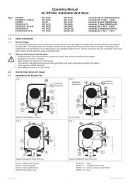
Model 8551 and 8551-N vent valve, PN 160, DN 15-50<br />
1.0 Safety instructions<br />
1.1 Proper use<br />
Any improper use, intervention in the design and deviation from the design data automatically lead to<br />
termination of the warranty. The vent valve is designed for the discharge of air from liquid systems. Any<br />
other use is not permissible. The manufacturer is not liable for damage resulting from any other use.<br />
The user or operator bears the risk in this case. This also applies analogously to incorrect assembly,<br />
start up, use and maintenance.<br />
1.2 Warnings and symbols<br />
■ Personal risk due to escaping operating medium as well as because of pressure, temperature and<br />
weight. Failure to comply with these warnings results in the risk of accidents.<br />
■Follow the instructions in this operating <strong>manual</strong>.<br />
■The operator must ensure that this operating <strong>manual</strong> and, if necessary, other relevant documents are<br />
available on site.<br />
■Only trained or instructed personnel may be employed here.<br />
■Any mode of operation that may impair safety must be avoided.<br />
2.0 General description and use<br />
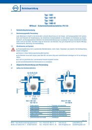
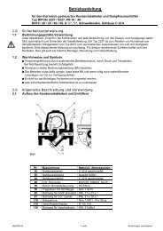
2.1 Design of the vent valve<br />
Item 1 Housing cover<br />
2 Housing gasket<br />
3 Housing with connections<br />
4 Control screw<br />
5 Set of screws with nuts<br />
6 Drain plug<br />
7 Float control<br />
8 Supporting structure with rotary slide valve<br />
9 Float with fork<br />
10 Supporting screw<br />
11 Seal for Supporting screw<br />
12 Seal for drain plug<br />
13 Seal for control screw<br />
Rev. 03/2012-Di Page 1 of 5 Subject to modification !
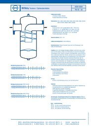
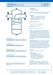
2.2 Design of the automatic venting unit<br />
2.3 Function-limit of control units<br />
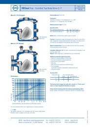
2.4 Performance<br />
2.5 Function / installation<br />
The float control assembly discharges air and gases from all liquid carrying systems without time lag,<br />
independent of pressure and temperature variations. With the float in the lower position the outlet crosssection<br />
is open. Air and gases escape through the upturned immersion tube. Rising of the liquid level<br />
lifts the float and causes to close the outlet.<br />
� Remove protective caps from inlet and outlet.<br />
� Fitting position according to figure (page 1)<br />
� Flow direction according to the arrow provided on the rating plate<br />
� Support: The weight of the condensate trap must be taken up by a holding device and<br />
support. The condensate trap weight approx. 40-50 kg.<br />
Rev. 03/2012-Di Page 2 of 5 Subject to modification !
Rev. 03/2012--Di<br />
TTo<br />
avoid dowwn<br />
times, it iss<br />
recommended<br />
that prov vision be maade<br />
for a shuut-off<br />
device with w a by-passs<br />
line<br />
bboth<br />
in front of and behinnd<br />
the condeensate<br />
trap<br />
3.0 SStart<br />
up<br />
TThe<br />
pressuree<br />
build-up annd<br />
heating-up<br />
of the hous sing should nnot<br />
take placce<br />
abruptly. If f leaks occurr<br />
due<br />
tto<br />
so-called ssettling<br />
afterr<br />
the first starrtup,<br />
the scre ews (items 4,<br />
5, 6,10) cann<br />
be retighte ened taking innto<br />
aaccount<br />
the indicated torrque.<br />
Retighttening<br />
may only o be carrieed<br />
out when the housing is depressuurized<br />
aand<br />
at most warm to thee<br />
touch.<br />
4.0<br />
Maintenance<br />
/ inspecction<br />
4.1 OOpening<br />
thee<br />
automatic venting uniit<br />
and disma antling the ffloat<br />
controll<br />
� The ventinng<br />
unit must be depressuurized.<br />
Shut off o the systemm<br />
securely inn<br />
front of and d behind the<br />
aautomatic<br />
venting<br />
unit.<br />
� Release aany<br />
remaininng<br />
pressure in<br />
the housin ng by loosening<br />
screw (4) ) or (6) by on nly a quarter turn.<br />
TThe<br />
weight oof<br />
the automaatic<br />
venting unit<br />
must be ta aken up by a support, e.gg.<br />
and must be taken outt<br />
of<br />
tthe<br />
pipeline ssystem.<br />
� Loosen housing<br />
bolts (5) evenly crosswise.<br />
Pu ull down loweer<br />
housing seection<br />
(3).<br />
4.2 DDismantlingg<br />
the float coontrol<br />
� Loosen suupport<br />
bolt (110)<br />
and screew<br />
out 1 to 2 turns.<br />
��<br />
Tap gentlyy<br />
on the frontt<br />
end of the ssupport<br />
bolt (10) ( with a plastic<br />
mallet. .<br />
��<br />
This looseens<br />
the controol<br />
from the cconical<br />
housing<br />
seat.<br />
� Screw out<br />
support bolt<br />
(10) with seeal<br />
(11) com mpletely.<br />
Remove ffloat<br />
control.<br />
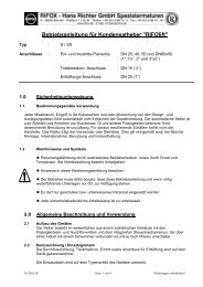
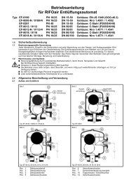
4.3 DDisassembling<br />
and cleaaning<br />
the flooat<br />
control<br />
1. After remooving<br />
the cottter<br />
pin (k), thhe<br />
rotary valv ve (i) is simpply<br />
pulled outt<br />
to the sidee.<br />
22.<br />
Clean the parts using, for examplee,<br />
benzine.<br />
33.<br />
Check thee<br />
rotary valvee<br />
(i) for wear along the se ealing edge. If wear is<br />
detected, the<br />
support boody<br />
(8) togetther<br />
with the rotary valve (i) must be rreplaced.<br />
A careful lleak<br />
test muust<br />
be carriedd<br />
out by RIFO OX.<br />
44.<br />
During asssembly<br />
ensuure<br />
that the nnotch<br />
in the rotary r valve ( (i) points to thhe<br />
punch ma ark<br />
on the suppport<br />
body (88)<br />
and the cootter<br />
pin (k) is s inserted annd<br />
secured again<br />
carefully.<br />
55.<br />
It must bee<br />
possible to move the flooat<br />
up and do own easily byy<br />
hand.<br />
4.4 IInstalling<br />
thhe<br />
float conttrol<br />
� The compplete<br />
float conntrol<br />
is insertted<br />
into the conical c housing<br />
seat with the support body (10). Itt<br />
must<br />
bbe<br />
ensured hhere<br />
that the float is posittioned<br />
in the center of thee<br />
housing (1).<br />
� Screw in ssupport<br />
bolt ( (10) with gassket<br />
(11) and d tighten withh<br />
a standard ring wrench. Tightening ttorque<br />
aaccording<br />
to the section 4.7.<br />
4.5 AAssemblingg<br />
the ventingg<br />
automat<br />
� Check thee<br />
housing gassket<br />
(2) and replace nece essary.<br />
� Mount the lower housing<br />
part (3) wwith<br />
upper ho ousing part (11)<br />
� Tighten the<br />
housing boolts<br />
(5) evenly<br />
crosswise.<br />
Tightening torque according<br />
to the section s 4.7.<br />
Page 3 of 5<br />
puncch<br />
mark<br />
notcch<br />
Subject to modificaation<br />
!
4.6 Care and maintenance, spare parts<br />
� In the case of a great risk of dirt accumulation, the housing should be rinsed thoroughly from time to<br />
time, but while depressurized. If necessary, the float control should also be checked according to<br />
section 4.3.<br />
Spare parts: Only genuine spare parts may be used.<br />
Version 1.4571<br />
4.7 Screw tightening torque (at room temperature, coat thread with<br />
temperature-resistant lubricant)<br />
Position Tightening torque<br />
4 20 Nm<br />
5 70 Nm<br />
6 30 Nm<br />
10 25 Nm<br />
Rev. 03/2012-Di Page 4 of 5 Subject to modification !
5 Conformity assessment<br />
We declare conformity with Directive 97/23/EC of 29.05.97 for the following pressure equipment:<br />
Automatic venting unit, type:<br />
■ 8551, P265GH, DN 15-50: Fluid group 1, Category III, Module H<br />
■ 8551, 13CrMo4-5, DN 15-50: Fluid group 2, Category II, Module H<br />
■ 8551, 10CrMo9-10, DN 15-50: Fluid group 2, Category II, Module H<br />
■ 8551-N, 1.4571, DN 15-50: Fluid group 1, Category III, Module H<br />
The pressure equipment described is a pressure-keeping component in accordance with Article 1,<br />
2.1.4. Applied conformity assessment procedure according to Annex III:<br />
Designated office: Lloyd’s Register Quality Assurance <strong>GmbH</strong>, Am Sandtorkia 4, D-20457 Hamburg,<br />
Germany. Identification No. 0525<br />
In the case that the equipment is modified without our approval, this declaration shall no longer be valid.<br />
RIFOX-<strong>Hans</strong> <strong>Richter</strong> <strong>GmbH</strong><br />
Spezialarmaturen<br />
Rev. 03/2012-Di Page 5 of 5 Subject to modification !