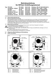
Operating manual - Rifox-Hans Richter GmbH
Operating manual - Rifox-Hans Richter GmbH
Operating manual - Rifox-Hans Richter GmbH

Create successful ePaper yourself
Turn your PDF publications into a flip-book with our unique Google optimized e-Paper software.
<strong>Operating</strong> Manual for Float-Controlled Condensate Trap<br />
Type: WU – 1001N / 1002 / 1004 / 1101 / 1101N / 1201N / EF – 1080N / 1180 / 1180N / 1280N<br />
Connections, depending on type: Flanges DIN / ANSI DN 15 – 50 /<br />
Socket thread G ¾, G 1 / Welded ends, socket weldings<br />
1.0 Safety instructions<br />
1.1 Proper use<br />
Any improper use, intervention in the design and deviation from<br />
the design data automatically lead to termination of the<br />
warranty. The from steam, compressed air and pressure gas<br />
systems. Any other use is not permissible. The manufacturer is<br />
not liable for damage resulting from any other use. The user or<br />
operator bears the risk in this case. This also applies<br />
analogously to incorrect assembly, startup, use and<br />
maintenance.<br />
1.2 Warnings and symbols<br />
� Personal risk due to escaping operating medium as well as<br />
because of pressure, temperature and weight. Failure to comply<br />
with these warnings results in the risk of accidents.<br />
� Follow the instructions in this operating <strong>manual</strong>.<br />
� The operator must ensure that this operating <strong>manual</strong> and, if<br />
necessary, other relevant documents are available on site.<br />
� Only trained or instructed personnel may be employed here.<br />
� Any mode of operation that may impair safety must be avoided.<br />
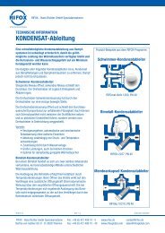
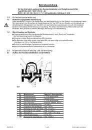
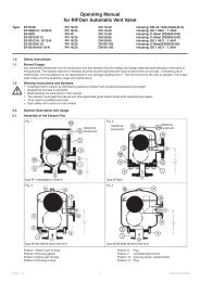
2.0 General description and use<br />
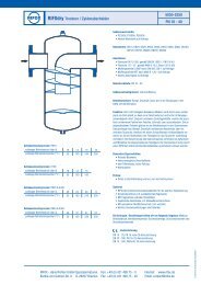
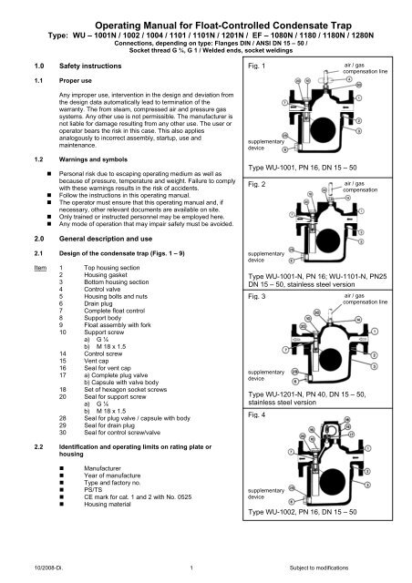
2.1 Design of the condensate trap (Figs. 1 – 9)<br />
Item 1 Top housing section<br />
2 Housing gasket<br />
3 Bottom housing section<br />
4 Control valve<br />
5 Housing bolts and nuts<br />
6 Drain plug<br />
7 Complete float control<br />
8 Support body<br />
9 Float assembly with fork<br />
10 Support screw<br />
a) G ¼<br />
b) M 18 x 1.5<br />
14 Control screw<br />
15 Vent cap<br />
16 Seal for vent cap<br />
17 a) Complete plug valve<br />
b) Capsule with valve body<br />
18 Set of hexagon socket screws<br />
20 Seal for support screw<br />
a) G ¼<br />
b) M 18 x 1.5<br />
28 Seal for plug valve / capsule with body<br />
29 Seal for drain plug<br />
30 Seal for control screw/valve<br />
2.2 Identification and operating limits on rating plate or<br />
housing<br />
� Manufacturer<br />
� Year of manufacture<br />
� Type and factory no.<br />
� PS/TS<br />
� CE mark for cat. 1 and 2 with No. 0525<br />
� Housing material<br />
Fig. 1<br />
supplementary<br />
device<br />
Type WU-1001, PN 16, DN 15 – 50<br />
Type WU-1001-N, PN 16; WU-1101-N, PN25<br />
DN 15 – 50, stainless steel version<br />
Type WU-1201-N, PN 40, DN 15 – 50,<br />
stainless steel version<br />
Type WU-1002, PN 16, DN 15 – 50<br />
10/2008-Di. 1 Subject to modifications<br />
air / gas<br />
compensation line<br />
Fig. 2 air / gas<br />
compensation<br />
supplementary<br />
device<br />
Fig. 3<br />
supplementary<br />
device<br />
Fig. 4<br />
supplementary<br />
device<br />
air / gas<br />
compensation line
Fig. 6<br />
supplemen<br />
tary device<br />
Type WU-1004, PN 16, DN 15 – 50<br />
Fig. 7<br />
Type EF-1180, PN 25, DN 15 – 50<br />
Fig. 8<br />
Suppleme<br />
tary device,<br />
control and<br />
relief screw<br />
Type EF-1080-N, PN16, DN 15 – 50, stainless steel<br />
Type EF-1180-N, PN25, DN 15 – 50, stainless steel<br />
Fig. 9<br />
Type EF-1280-N, PN40, DN 25–50, stainless steel<br />
Fig. 10<br />
punch mark<br />
notch<br />
2.3 Functional limits of float control (PMO in bar)<br />
Crosssection<br />
Type<br />
1001/1001-N<br />
1080/1080-N<br />
Type<br />
1002/1004<br />
Type<br />
1101-N/<br />
1180/1180-N<br />
10/2008-Di. 2<br />
Subject to modifications<br />
Type<br />
1201-N/<br />
1280-N<br />
H C H C H C H C<br />
Id 20 25<br />
IId 18 23<br />
IIa 32 40<br />
III 13 16 13 - 13 16 13 16<br />
IV 11 14 11 - 11 14 11 14<br />
V 2.5 2.8 2.5 - 2.5 2.8 2.5 2.8<br />
VI 13 16 13 - 16 25 20 30<br />
VIa - - - - 20 25 30 30<br />
VII 12 16 12 - 16 23 16 23<br />
VIIIa 4 5 4 - 4 5 4 5<br />
VIIIb 4 4.5 4 - 4 4.5 4 4.5<br />
SQ / SK Special model. Design according to process data.<br />
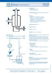
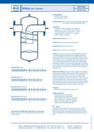
2.4 Function / installation / venting / gas compensation<br />
Due to its gravity, the condensate flows down to the deepest<br />
point, i.e. to the condensate trap housing. A rising condensate<br />
level lifts the float and the valve opening is opened through the<br />
float fork / rotary valve connection. When the condensate level<br />
drops, the control closes.<br />
� In the case of steam, automatic venting is advantageous (see<br />
section 2.5). For <strong>manual</strong> venting: loosen item (4)and/or (14) by a<br />
quarter turn.<br />
� For proper function of the float control with pressure<br />
gases, the gas in the condensate trap housing must be able to move<br />
into the gas space with the same operating pressure above the<br />
condensate trap (pressure compensation). For this purpose the screw<br />
or control valve (4) or (14) can be replaced by a cutting ring union and<br />
a compensating line leading upward can be installed.<br />
� In the case of pressure gases, a speical gastight under-level float<br />
control is nearly exclusively used (if necessary, consult <strong>Rifox</strong>).<br />
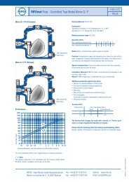
2.5 Venting via the automatic thermal vent valve (Figs. 4+6)<br />
Fig. 4: Air and gases are vented inward, i.e. to the condensate outlet,<br />
in the startup and operating mode via the rugged bimetal control<br />
system.<br />
Fig. 6: Quick-action startup and continuous venting with high capacity,<br />
also inward to the condensate outlet.<br />
Vent jet: Rugged continuous venting to the condensate outlet. Not<br />
suitable for higher venting capacity.<br />
3.0 Assembly<br />
3.1 Fitting position<br />
The condensate trap hangs with the housing (3) facing down in the<br />
center of the pipeline (see Figs. 1 to 9). The top housing section (1)<br />
can remain in the pipeline when the float control is dismantled.<br />
3.2 Installation<br />
� The condensate trap is flange-mounted, screwed or welded into the<br />
condensate line between flanges according to design and type.<br />
� Remove protective caps from condensate inlet and outlet.<br />
� Fitting position according to Figs. 1 to 9 or section 3.1.<br />
� According to the direction of the arrow cast on the housing.<br />
� Support: In the case of size DN 40/50, ensure adequate support in<br />
front of and behind the condensate trap. Condensate trap weight<br />
approx. 28 kg.<br />
� To avoid down times, it is recommended that a shut-off device with a by-pass<br />
line be installed both in front of and behind the condensate trap.<br />
4.0 Startup<br />
The pressure build-up and heating-up of the housing should not take<br />
place abruptly. If leaks occur due to so-called settling after the first<br />
startup, the screws (items 5, 6, 10, 14) can be retightened taking into<br />
account the indicated torque. Retightening may only be carried out<br />
when the housing is depressurized and at most warm to the touch.
5.0 Monitoring and checks<br />
Malfunctions arise either as condensate backup or steam entry into the condensate system.<br />
Condensate backup can be determined: a) with screw (4) or (14): loosen item (4) or (14) by only a quarter turn<br />
ensuring that no condensate escapes; and b) in the case of steam applications, with a surface thermometer on the<br />
housing (if necessary, consult RIFOX).<br />
Steam or gas entry can be determined with an ultrasonic measuring device, e.g. RIFOX – USD 9050, and in the<br />
steam section also with a surface thermometer. In the case of steam entry, check control (7) and (17) and replace if<br />
necessary (consult RIFOX if required).<br />
6.0 Maintenance / inspection<br />
6.1 Opening the condensate trap and dismantling the float control<br />
1.The condensate trap must be depressurized. Shut off the system securely in front of and behind the condensate<br />
trap.<br />
2. Release any remaining pressure in the housing by loosening screw (4) or (14) by only a quarter turn.<br />
3. Loosen housing bolts (5) evenly crosswise. Pull down bottom housing section (3) (top housing section [1] remains in<br />
the pipeline).<br />
4. Loosen support bolt (10) and screw out 1 to 2 turns.<br />
5. Tap gently on the front end of the support bolt (10) with a plastic mallet. This loosens the control from the conical<br />
housing seat.<br />
6. Screw out support bolt (8) completely. Remove float control.<br />
6.2 Disassembling and cleaning the float control<br />
1. After removing the cotter pin (k), the rotary valve (i) is simply pulled out to the side.<br />
2. Clean the parts using, for example, benzine.<br />
3. Check the rotary valve (i) for wear along the sealing edge. If wear is detected, the<br />
support body (8) together with the rotary valve (i) must be replaced. A careful leak test<br />
must be carried out by RIFOX.<br />
4. During assembly ensure that the notch in the rotary valve (i) points to the punch mark<br />
on the support body (8) and the cotter pin (k) is inserted and secured again carefully.<br />
5. It must be possible to move the float up and down easily by hand.<br />
10/2008-Di. 3<br />
Subject to modifications<br />
punch mark<br />
6.3 Installing the control and assembling the condensate trap<br />
1. The complete float control is inserted into the conical housing seat with the support body (8). It must be ensured<br />
here that the float is positioned in the center of the housing.<br />
2. The support body (8) is fixed in the conical housing seat with a gentle tap of the plastic mallet on the front end of the<br />
immersion tube.<br />
3. Screw in support bolt (10) with gasket (20) and tighten with a standard ring wrench. For tightening torque see page 4<br />
4. Check the housing gasket (2) and replace necessary.<br />
5. Tighten the housing bolts (5) evenly crosswise. For tightening torque see page 4.<br />
6.4 Care and maintenance, spare parts<br />
� In the case of a great risk of dirt accumulation, the housing should be rinsed thoroughly from time to time, but while<br />
depressurized. If necessary, the float control should also be checked according to section 6.2.<br />
� Dirt that has collected in the housing can be emptied after removal of the screw plug (6).<br />
� In special cases it may be useful to install a separate dirt trap upstream.<br />
� In most cases the float control does not require special care. Maintenance primarily depends on the wear resistance<br />
of the valve seal. See sections 6.1 and 6.2 in this connection.<br />
Spare parts: Only genuine spare parts may be used.<br />
Item Designation Dimension / DIN Design / material<br />
2 Housing gasket for<br />
138 x 132<br />
158 x 150<br />
195 x 188<br />
197 x 188<br />
4 Control valve G ¼ standard stainless steel<br />
5 Housing bolts with nuts DN 15-25 (depending on type)<br />
1) M 12 2) M 14 3) M 16<br />
DN 40/50 (depending on type)<br />
1) M 16 2) M 20<br />
6 Drain plug G ½, DIN 910 steel 5.8<br />
7 Complete float control For size see front end of<br />
support bolt item 10<br />
notch<br />
a) Cu b) soft iron c) stainless steel profiled graphite d) PTFE<br />
a) PTFE b) stainless steel profiled graphite<br />
a) Cu b) soft iron c) stainless steel profiled graphite<br />
PTFE<br />
a) 8.8 b) A4-70<br />
a) standard stainless steel<br />
b) 1.4571<br />
8 Support bolt compl. with rotary valve Ditto a) standard stainless steel b) 1.4571<br />
9 Float assembly with fork Ditto a) 1.4301 b) 1.4571<br />
10 Support bolt 1) G ¼ 2) M 18 x 1.5 a) 1.4104 b) 1.4571<br />
14 Control screw G ¼ a) 1.4104 b) 1.4571<br />
16 Seal for vent cap 60 x 52 graphite with plate
17 a) Complete plug valve<br />
b) Capsule with valve body<br />
Standard, s = 2, h = 1.5<br />
standard, type S<br />
18 Set of hexagon socket screws M 8 A4-70<br />
Standard stainless steel / bimetal<br />
stainless steel / HC4<br />
20 Seal for support bolt 1) D = 22 2) D = 28 a) Cu b) soft iron c) stainless steel profiled graphite d) PTFE<br />
28 Seal for plug valve or valve body capsule for G 3/8 a) Cu b) soft iron<br />
29 Seal for drain plug for G ½ a) Cu b) soft iron c) stainless steel profiled graphite<br />
30 Seal for control valve / control screw dia = 18 a) Cu b) soft iron c) stainless steel profiled graphite d) PTFE<br />
6.5 Screw tightening torque (at room temperature, coat thread with temperature-resistant lubricant)<br />
Type DN Housing gasket<br />
Item 2<br />
Screws<br />
Item 5<br />
Torque<br />
Item 5<br />
Seal<br />
Item 12/20<br />
10/2008-Di. 4<br />
Subject to modifications<br />
Torque<br />
Item 10<br />
1002/ 1004 15 - 25 Cu and soft iron M 12, 8.8 60 Nm Cu and soft iron 60 Nm<br />
1002/ 1004 40 / 50 a) Cu<br />
b) soft iron<br />
1001-N / 1080-N 15 - 25 a) PTFE<br />
b) stainless steel profiled graphite<br />
1001-N / 1080-N 40 / 50 a) PTFE<br />
b) stainless steel profiled graphite<br />
1101-N / 1180-N 15 – 25 a) PTFE<br />
b) stainless steel profiled graphite<br />
1001-N / 1080-N 40 / 50 a) PTFE<br />
b) stainless steel profiled graphite<br />
M 16, A4-70 a) 100-110 Nm<br />
b) 80 Nm<br />
M 14, A4-70 a) 25 Nm<br />
b) 60 Nm<br />
M 16, A4-70 a) 25 Nm<br />
b) 70 Nm<br />
M 14, A4-70 a) 25 Nm<br />
b) 60 Nm<br />
M 16, A4-70 a) 25 Nm<br />
b) 60 Nm<br />
Cu and soft iron 100 Nm<br />
a) PTFE<br />
b) stainless steel profiled graphite<br />
a) PTFE<br />
b) stainless steel profiled graphite<br />
a) PTFE<br />
b) stainless steel profiled graphite<br />
a) PTFE<br />
b) stainless steel profiled graphite<br />
a) 12 Nm<br />
b) 20 Nm<br />
a) 15-20 Nm<br />
b) 40 Nm<br />
a) 12 Nm<br />
b) 20 Nm<br />
a) 15-20 Nm<br />
b) 40 Nm<br />
1180 15 – 25 Cu and soft iron M 14, 8.8 90 Nm Cu and soft iron 60 Nm<br />
1180 40 / 50 a) Cu<br />
b) soft iron<br />
1201-N / 1280-N 15 - 25 a) PTFE<br />
b) stainless steel profiled graphite<br />
1201-N / 1280-N 40 / 50 a) PTFE<br />
b) stainless steel profiled graphite<br />
M 16, A4-70 a) 100-110 Nm<br />
b) 80 Nm<br />
M 16, A4-70 a) 25 Nm<br />
b) 70 Nm<br />
M 20, A4-70 a) 40 Nm<br />
b) 90 Nm<br />
Cu and soft iron 100 Nm<br />
a) PTFE<br />
b) stainless steel profiled graphite<br />
a) PTFE<br />
b) stainless steel profiled graphite<br />
7.0 Declaration of conformity CE<br />
We declare conformity with Directive 97/23/EC of 29.05.1997 for the following pressure equipment:<br />
Float-controlled condensate trap type<br />
1002 / 1004 DN 15 - 25: Art. 3, par. 3: no CE-Mark<br />
1101 / 1180 DN 15 - 25: Art. 3, par. 3: no CE-Mark<br />
1101 / 1180 DN 40 / 50: Cat. 2, fluid group 1, module H<br />
1001-N / 1101-N / 1080-N / 1180-N DN 15 - 25: Art. 3, par. 3: no CE-Mark<br />
1001-N / 1101-N / 1080-N / 1180-N DN 40 / 50: Cat. 2, fluid group 1, module H<br />
1201-N / 1280-N DN 15 - 25: Art. 3, par. 3: no CE-Mark<br />
1201-N / 1280-N DN 40 / 50: Cat. 2, fluid group 1, module H<br />
The pressure equipment described is a pressure-keeping component in accordance with Article 1, 2.1.4.<br />
Applied conformity assessment procedure according to Annex III.<br />
Designated office: Lloyd’s Register Quality Assurance <strong>GmbH</strong>, Mönkebergstr. 27, D-20095, Hamburg, Germany,<br />
identification no. 0525.<br />
In the case that the equipment is modified without our approval, this declaration shall no longer be valid.<br />
RIFOX – <strong>Hans</strong> <strong>Richter</strong> <strong>GmbH</strong> – Spezialarmaturen<br />
a) 12 Nm<br />
b) 20 Nm<br />
a) 15-20 Nm<br />
b) 40 Nm