
You also want an ePaper? Increase the reach of your titles
YUMPU automatically turns print PDFs into web optimized ePapers that Google loves.
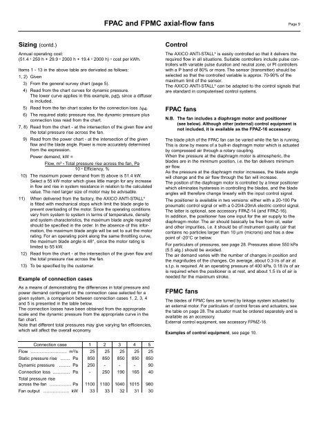
FPAC and FPMC axial-<strong>flow</strong> <strong>fan</strong>s Page 9Sizing (contd.)Annual operating cost:(51.4 x 250 h + 29.9 x 2000 h + 19.4 x 2000 h) x cost per kWh.Items 1 - 13 in the above table are derivated as follows:1, 2) Given3) From the general survey chart (page 5).4) Read from the chart curves for dynamic pressure.The lower curve applies in this example, pdD, since a diffuseris included.5) Read from the <strong>fan</strong> chart scales for the connection loss ∆p4.6) The required static pressure rise, the dynamic pressure plusconnection loss read from the chart.7, 8) Read from the chart - at the intersection of the given <strong>flow</strong> andthe total pressure rise across the <strong>fan</strong>.9) Read from the power chart - at the intersection of the given<strong>flow</strong> and the blade angle. Power is more accurately determinedfrom the expression.Power demand, kW =Flow, m³ x Total pressure rise across the <strong>fan</strong>, Pa10 x Efficiency, %10) The maximum power demand from 9) above is 51.4 kW.Select a 55 kW motor which gives little margin for any increasein <strong>flow</strong> and rise in system resistance in relation to the calculatedvalue. The next larger size of motor may be advisable.11) When delivered from the factory, the <strong>AXICO</strong> <strong>ANTI</strong>-STALL ®is fitted with mechanical stops which limit the blade angle toprevent overloading of the motor. Since the operating conditionsvary from system to system in terms of temperature, densityand system characteristics, the maximum blade angle requiredshould be specified in the order. In the absence of this information,the maximum blade angle will be set to suit the motorrating. For an operating point along the same throttling curve,the maximum blade angle is 48°, since the motor rating islimited to 55 kW.12) Read from the chart - at the intersection of the given <strong>flow</strong> andthe total pressure rise across the <strong>fan</strong>.13) To be specified by the customer.Example of connection casesAs a means of demonstrating the differences in total pressure andpower demand contingent on the connection case selected for agiven system, a comparison between connection cases 1, 2, 3, 4and 5 is presented in the table below.The connection losses have been obtained from the appropriatescale and the dynamic pressure from the appropriate curve in the<strong>fan</strong> chart.Note that different total pressures may give varying <strong>fan</strong> efficiencies,which will affect the overall economy.ControlThe <strong>AXICO</strong> <strong>ANTI</strong>-STALL ® is easily controlled so that it delivers therequired <strong>flow</strong> in all situations. Suitable controllers include pulse controllerswith variable pulse duration and neutral zone, or PI controllerswith a P band of 80% or more. The sensor (transmitter) should beselected so that the controlled variable is approx. 70-90% of themaximum limit of the sensor.The <strong>AXICO</strong> <strong>ANTI</strong>-STALL ® can be adapted to the control signals thatare standard in computerised control systems.FPAC <strong>fan</strong>sN.B. The <strong>fan</strong> includes a diaphragm motor and positioner(see below). Although other (external) control equipment isnot included, it is available as the FPAZ-16 accessory.The blade pitch of the FPAC <strong>fan</strong> can be varied while the <strong>fan</strong> is running.This is done by means of a built-in diaphragm motor which is actuatedby compressed air through a rotary coupling.When the pressure at the diaphragm motor is atmospheric, theblades are in the minimum position, i.e. the <strong>fan</strong> delivers minimumair <strong>flow</strong>.As the pressure at the diaphragm motor increases, the blade anglewill change and the air <strong>flow</strong> through the <strong>fan</strong> will increase.The position of the diaphragm motor is controlled by a linear positionerwhich eliminates hysteresis in controlling the blades, and the bladeangles will therefore change linearly with the input control signal.The positioner is available in two versions: either with a 20-100 Papneumatic control signal or with a 0-20/4-20mA electric control signal.The latter is optional, see accessory FPAZ-14 (and FPAZ-16).In addition, the positioner has one input for the air supply to thediaphragm motor. The air should basically be free from oil, waterand other impurities, i.e. it should be of instrument quality (air thatcontains no particles larger than 10 µm (microns) and has a dewpoint of -20°C or below.For particulars of pressures, see page 28. Pressures above 550 kPa(5.5 atg.) should be avoided.The air demand varies with the number of changes in position andthe magnitudes of the changes. On average, about 0.3 l/s of air ats.t.p. is required. At an operating pressure of 400 kPa, 0.18 l/s of airis required when the positioner is at rest, and about 1.5 l/s of air isneeded for the maximum stroke.FPMC <strong>fan</strong>sThe blades of FPMC <strong>fan</strong>s are turned by linkage system actuated byan external motor. For particulars of control forces and actuators, seethe table on page 28. The actuator must be ordered separately and isavailable as an accessory.External control equipment, see accessory FPMZ-16.Examples of control equipment, see page 10.Connection case 1 2 3 4 5Flow ............................. m³/s 25 25 25 25 25Static pressure rise ........ Pa 850 850 850 850 850Dynamic pressure ......... Pa 250 - - - 90Connection loss .............. Pa - 250 190 165 40Total pressure riseacross the <strong>fan</strong> .................. Pa 1100 1100 1040 1015 980Fan output ..................... kW 33 33 32 31 30