
You also want an ePaper? Increase the reach of your titles
YUMPU automatically turns print PDFs into web optimized ePapers that Google loves.
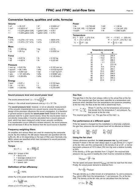
FPAC and FPMC axial-<strong>flow</strong> <strong>fan</strong>s Page 33Conversion factors, qualities and units, formulaeVolume1 m³ = 35.3 ft³ 1 ft³ = 0.0283 m³1 cm³ = 0.0610 in³ 1 in³ = 16.4 cm³1 l = 0.220 gallon (UK) 1 gallon (UK) = 4.55 l1 l = 0.264 gallon (US) 1 gallon (US) = 3.79 lFlow1 m³/h = 0.278 x 10 - ³ m³/s 1 m³/s = 3600 m³/h1 cfm = 0.472 x 10 - ³ m³/s 1 m³/s = 2120 m³/hMass1 lb = 0.454 kg 1 kg = 2.2 lb1 oz = 28.3 g 1 g = 0.0352 ozForce1 kg = 9.81 N 1 N = 0.102 kg1 lbf = 4.45 N 1 N = 0.225 lbfPressure1 mm vp = 9.81 Pa 1 Pa = 0.102 mm vp1 kp/cm² = 98.1 kPa 1 kPa = 0.0102 kp/cm²1 kp/cm² = 0.891 bar 1 bar = 1.021 kp/cm²1 atm = 101.325 kPa 1 kPa = 0.00987 atm1 lbf/in² = 6.89 kPa 1 kPa = 0.145 lbf/in²Energy1 kpm = 9.81 J 1 J = 0.102 kpm1 cal = 4.19 J 1 J = 0.239 cal1 kWh = 3.60 MJ 1 MJ = 0.278 kWhPower1 hk = 0.736 kW 1 kW = 1.36 hk1 hk (UK, US) = 0.746 kW 1 kW = 1.34 (UK, US)1 kcal/h = 1.16 W 1 W = 0.860 kcal/hTemperature0°C = 32°F = 273.15 K 0°F = - 17.8°C = 255.4 KK = 0°C + 273.15 °F = 1.8 (°F - 273.15) + 32°C = 5 (°F - 32) °F = 5 (°C + 32)9 9Temperature conversion°F °C K0 - 17.8 255.410 - 12.2 261.020 - 6.7 266.530 - 1.1 272.032 0 273.1540 4.4 277.650 9.9 283.160 15.5 288.770 21.0 294.280 26.6 299.890 32.1 305.3100 37.8 311.0Sound pressure level and sound power levelp 2The sound pressure level Lp = 10 log p dB owhere p = the actual sound pressure and po = 2 x 10 -5 Pa.The sound pressure level, however, is not an absolute measurementof the acoustic characteristics at a sound source, since the acousticdesign of the premises influences the sound propagation. It is thereforein general easiest to specify the sound power level instead of the soundpressure level for a given sound source. Since the sound power level isnot directly measurable, it must be calculated from a sound pressurelevel, which has been measured under known acoustic conditions.If no reverberation occurs (difficult to achieve indoors!), the sound pressurelevel will decrease 6 dB as the distance from the sound source is doubled.Frequency weighting filtersAn amplifier and various filters are used for measuring the compositesound. By this method, the dB-values measured are specified with thesuffix (A), (B) or (C) depending on the type of filter used. Normally onlydB(A) values are specified which best correspond to sound perceivedby the human ear.TorqueM = F x rM = 9550 x Pnwhere M = torque in NmF = force in Nr = leverage (radius) in mP = power in kW (motor)n = speed, rpmDefinition of <strong>fan</strong> efficiencyη = P x 100%Pewhere Pe is the power demand and P is the theoretical power fromGasP = q x ∆ pt kW,1000where q is in m³/s and ∆pt in Pa.<strong>flow</strong>The gas <strong>flow</strong> in the <strong>fan</strong> chart always refers to the actual <strong>flow</strong> at the <strong>fan</strong>inlet. If the required gas <strong>flow</strong> has been specified at a temperature andpressure which deviates from the temperature and pressure prevailingat the <strong>fan</strong> inlet, the <strong>flow</strong> at the <strong>fan</strong> inlet is determined from:q = q1 T Where x x Pa1T1 and Pa1 are the temperature and pressurethat deviate from the temperature T, and pressure, Pa,T1 x Pathat prevail at the <strong>fan</strong> inlet.The required gas <strong>flow</strong> = q1. The gas <strong>flow</strong> at the inlet = q.Fan performance at a different speedIf the <strong>fan</strong> speed is changed but the installation is otherwise unaltered,the gas <strong>flow</strong>, pressure rise and power level will be affected as follows:q1 n1 =∆pt1 n 2 P1 = 1n 3=1q2 n2 ∆pt2n 2 P2 n 2Using the <strong>fan</strong> chartUnless otherwise specified, the total pressure rise ∆pt and powerdemand P shown in the <strong>fan</strong> chart always apply to a gas density of 1.2 kg/m³at the <strong>fan</strong> inlet, and this corresponds to the density of air at 20°, a normalbarometric pressure of 1013 mbar (760 mm Hg) and a relative humidityof 50%.If the density ρ of the gas deviates from 1.2 kg/m³, the required totalpressure rise ∆pt used in reading the chart must be corrected as follows:∆ptchart = 1.2 xρ∆ptThe <strong>fan</strong> speed and power demand Pechart can then be read from the chart.Finally, the actual power demand is obtained from:Pe = ρ x1.2PechartThe gas density ρo is often known at a temperature, To, and a pressure,Pao , which differ from the temperature, T, and pressure, Pa, at the <strong>fan</strong>inlet. The density at the <strong>fan</strong> inlet can be calculated from the formula:ρ = ρο T ox xPaT Pao