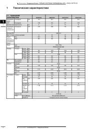
FPAC and FPMC axial-<strong>flow</strong> <strong>fan</strong>s Page 32Dimensions and weightsAccessoriesEBGA/EBGG flanges and EBGV grouting-in frameCircular, geometric size series.The flanges are designed according to ISO 6580, which isequivalent to EUROVENT 1/2.For particulars of finish, see the ordering key.EBGA EBGG EBGVhhtt2t2hhhEBGA- Flat bar flange, steelEiD dia.D dia.D dia.EBGG- Angle flange, steelEBGV- Grouting-in frame, steel (with dome nuts)n holes G dia.n holes G dia.n holes Jwith dome nutsSizeWeight, kgEBGA-a-bbbEBGG-a-bbbEBGGEBGV-a-bbbD E G J h n t1 t2 EBGAEBGV035 359 395 10 M8 35 8 6 6 2.1 3.9040 406 450 12 M10 40 8 6 5 2.6 4.2045 456 500 12 M10 40 8 6 5 2.9 4.7050 506 560 12 M10 50 12 6 6 3.5 7.8056 566 620 12 M10 50 12 6 6 4.6 9.0063 636 690 12 M10 50 12 6 6 5.1 9.7071 716 770 12 M10 50 16 6 6 5.7 10.9080 808 860 12 M10 50 16 6 6 6.3 12.1090 908 970 15 M12 60 16 6 6 8.6 16.4100 1008 1070 15 M12 60 16 6 6 9.5 18.1112 1128 1190 15 M12 60 20 6 6 10.5 20.1125 1258 1320 15 M12 60 20 6 6 11.7 22.3140 1412 1470 15 M12 60 20 6 6 13.1 24.9160 1612 1680 19 M16 60 24 8 6 14.9 28.3180 1812 1880 19 M16 60 24 8 6 16.6 31.7200 2012 2080 19 M16 60 24 8 6 18.4 35.1224 2240 2320 19 M16 80 28 10 8 45.2 67.7Anti-vibration mountings2 holes d dia. for retaining boltsL16L17Anti-vibration mountings for arr. 1H5L18AntivibrationL16 L17 L18 dH5 whenmountingsloadedA 110 128 82 11 30B 144 172 110 13.5 37C 182 212 152 13.5 47Size MotorAnti-vibrationmountings080 All A090132S - 160LA180M - 200LB100 All B112 All B125180M - 225MB250m - 315SCAnti-vibration mountings for arr. 6,horizontal installationSize MotorAnti-vibrationmountings080 All A090 All A100160M - 200LA225S - 225MB112160M - 160LA180M - 280MB125 All B140180M - 280MB315S - 315LC160225S - 225MB250M - 355SC180 All CAnti-vibration mountings for arr. 7Size MotorAnti-vibrationmountings080 All A090132S - 180LA200LB100 All B112 All B125 All B140200L - 280MB315S - 355SC160 All C180 All CAnti-vibration mountings for arr. 6,vertical installationSize MotorAnti-vibrationmountings080 All A090 All A100160M - 200LA200L - 225MB112 All B125 All B140200L - 280MB315S - 315LC160225S - 225MB250M - 355SC180 All CAnti-vibration mountings for arr. 3Size MotorAnti-vibrationmountings080 All B090 All B100200L - 250MB280S - 280MC112225S - 250MB250M - 315SC
FPAC and FPMC axial-<strong>flow</strong> <strong>fan</strong>s Page 33Conversion factors, qualities and units, formulaeVolume1 m³ = 35.3 ft³ 1 ft³ = 0.0283 m³1 cm³ = 0.0610 in³ 1 in³ = 16.4 cm³1 l = 0.220 gallon (UK) 1 gallon (UK) = 4.55 l1 l = 0.264 gallon (US) 1 gallon (US) = 3.79 lFlow1 m³/h = 0.278 x 10 - ³ m³/s 1 m³/s = 3600 m³/h1 cfm = 0.472 x 10 - ³ m³/s 1 m³/s = 2120 m³/hMass1 lb = 0.454 kg 1 kg = 2.2 lb1 oz = 28.3 g 1 g = 0.0352 ozForce1 kg = 9.81 N 1 N = 0.102 kg1 lbf = 4.45 N 1 N = 0.225 lbfPressure1 mm vp = 9.81 Pa 1 Pa = 0.102 mm vp1 kp/cm² = 98.1 kPa 1 kPa = 0.0102 kp/cm²1 kp/cm² = 0.891 bar 1 bar = 1.021 kp/cm²1 atm = 101.325 kPa 1 kPa = 0.00987 atm1 lbf/in² = 6.89 kPa 1 kPa = 0.145 lbf/in²Energy1 kpm = 9.81 J 1 J = 0.102 kpm1 cal = 4.19 J 1 J = 0.239 cal1 kWh = 3.60 MJ 1 MJ = 0.278 kWhPower1 hk = 0.736 kW 1 kW = 1.36 hk1 hk (UK, US) = 0.746 kW 1 kW = 1.34 (UK, US)1 kcal/h = 1.16 W 1 W = 0.860 kcal/hTemperature0°C = 32°F = 273.15 K 0°F = - 17.8°C = 255.4 KK = 0°C + 273.15 °F = 1.8 (°F - 273.15) + 32°C = 5 (°F - 32) °F = 5 (°C + 32)9 9Temperature conversion°F °C K0 - 17.8 255.410 - 12.2 261.020 - 6.7 266.530 - 1.1 272.032 0 273.1540 4.4 277.650 9.9 283.160 15.5 288.770 21.0 294.280 26.6 299.890 32.1 305.3100 37.8 311.0Sound pressure level and sound power levelp 2The sound pressure level Lp = 10 log p dB owhere p = the actual sound pressure and po = 2 x 10 -5 Pa.The sound pressure level, however, is not an absolute measurementof the acoustic characteristics at a sound source, since the acousticdesign of the premises influences the sound propagation. It is thereforein general easiest to specify the sound power level instead of the soundpressure level for a given sound source. Since the sound power level isnot directly measurable, it must be calculated from a sound pressurelevel, which has been measured under known acoustic conditions.If no reverberation occurs (difficult to achieve indoors!), the sound pressurelevel will decrease 6 dB as the distance from the sound source is doubled.Frequency weighting filtersAn amplifier and various filters are used for measuring the compositesound. By this method, the dB-values measured are specified with thesuffix (A), (B) or (C) depending on the type of filter used. Normally onlydB(A) values are specified which best correspond to sound perceivedby the human ear.TorqueM = F x rM = 9550 x Pnwhere M = torque in NmF = force in Nr = leverage (radius) in mP = power in kW (motor)n = speed, rpmDefinition of <strong>fan</strong> efficiencyη = P x 100%Pewhere Pe is the power demand and P is the theoretical power fromGasP = q x ∆ pt kW,1000where q is in m³/s and ∆pt in Pa.<strong>flow</strong>The gas <strong>flow</strong> in the <strong>fan</strong> chart always refers to the actual <strong>flow</strong> at the <strong>fan</strong>inlet. If the required gas <strong>flow</strong> has been specified at a temperature andpressure which deviates from the temperature and pressure prevailingat the <strong>fan</strong> inlet, the <strong>flow</strong> at the <strong>fan</strong> inlet is determined from:q = q1 T Where x x Pa1T1 and Pa1 are the temperature and pressurethat deviate from the temperature T, and pressure, Pa,T1 x Pathat prevail at the <strong>fan</strong> inlet.The required gas <strong>flow</strong> = q1. The gas <strong>flow</strong> at the inlet = q.Fan performance at a different speedIf the <strong>fan</strong> speed is changed but the installation is otherwise unaltered,the gas <strong>flow</strong>, pressure rise and power level will be affected as follows:q1 n1 =∆pt1 n 2 P1 = 1n 3=1q2 n2 ∆pt2n 2 P2 n 2Using the <strong>fan</strong> chartUnless otherwise specified, the total pressure rise ∆pt and powerdemand P shown in the <strong>fan</strong> chart always apply to a gas density of 1.2 kg/m³at the <strong>fan</strong> inlet, and this corresponds to the density of air at 20°, a normalbarometric pressure of 1013 mbar (760 mm Hg) and a relative humidityof 50%.If the density ρ of the gas deviates from 1.2 kg/m³, the required totalpressure rise ∆pt used in reading the chart must be corrected as follows:∆ptchart = 1.2 xρ∆ptThe <strong>fan</strong> speed and power demand Pechart can then be read from the chart.Finally, the actual power demand is obtained from:Pe = ρ x1.2PechartThe gas density ρo is often known at a temperature, To, and a pressure,Pao , which differ from the temperature, T, and pressure, Pa, at the <strong>fan</strong>inlet. The density at the <strong>fan</strong> inlet can be calculated from the formula:ρ = ρο T ox xPaT Pao