
You also want an ePaper? Increase the reach of your titles
YUMPU automatically turns print PDFs into web optimized ePapers that Google loves.
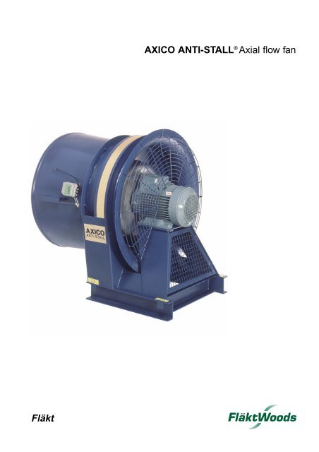
Fläkt<strong>AXICO</strong> <strong>ANTI</strong>-STALL ® <strong>Axial</strong> <strong>flow</strong> <strong>fan</strong>
The right to make alterations without notice is reserved.
FPAC and FPMC axial-<strong>flow</strong> <strong>fan</strong>s Page 3<strong>AXICO</strong> <strong>ANTI</strong>-STALL ®FPAC and FPMC axial-<strong>flow</strong> <strong>fan</strong>sFor variable air <strong>flow</strong> by means of controllable pitch blades.The <strong>fan</strong>s have completely stable <strong>flow</strong>/pressure characteristics,which eliminates the risk of surging.Air <strong>flow</strong> range: 3 - 110 m³/s (10 000 - 400 000 m³/h).Pressure rise: Up to 3000 Pa.Air temperature range: -15 to + 40°C with regard to theinsulation class of the motor.A quotation for a special versionfor other temperatures will besubmitted on request.• Good operating economy• Surge-free operation• Good control economy - the <strong>fan</strong> blades are instantlyset to meet the <strong>flow</strong> requirements of the installation,without impairing the high efficiency• Choice of suitable hub diameter and blade angle foroptimum matching to the desired operating point• Standard 4-pole or 6-pole foot-mounted motor ortwo-speed motor• Low vibration level• Low mass-moment of inertia - short starting time• Short overall length• Complete range of accessories• Surface treated with 80-micron coat of alkyd paintThe FPAC-1 axial-<strong>flow</strong> <strong>fan</strong> with CD guide vane diffuser.ApplicationsComfort ventilationAir handling units with <strong>AXICO</strong> <strong>ANTI</strong>-STALL ® <strong>fan</strong>s areused principally in hospitals, offices, hotels, exhibitionhalls, sports arenas, shopping centres and similar buildings.All efforts are being made to achieve maximum compactnessof conventional modular air handling units, in orderto minimize building costs and space requirements.The <strong>AXICO</strong> <strong>ANTI</strong>-STALL ® CD range of <strong>fan</strong>s has beendeveloped specifically for such air handling units.CD stands for compact design. To make the <strong>fan</strong> as compactas possible, the guide vane section is integrated witha diffuser. The CD converts dynamic pressure into staticwithout adding the length of a separate diffuser.Its short overall length makes the <strong>AXICO</strong> <strong>ANTI</strong>-STALL ® CD<strong>fan</strong> eminently suitable for all air handling units.Process ventilationWhat we normally recognize as process ventilation is thetype of ventilation used in industrial plants, power stations,mines, paint shops clean rooms, offshore installations,garages and so on. Common criteria of all these plantsare the strict demands as to factors such as reliability,resistance to corrosive environments (temperature, humidity),stable operating characteristics, spark-proof designand control accuracy.<strong>AXICO</strong> <strong>ANTI</strong>-STALL ® <strong>fan</strong>s usually meet the industrialrequirements and can be adapted to meet specificrequirements regarding materials, surface treatment,spark-proof design, special motors, special designs, etc.For particulars of the special variants available, consultyour nearest Fläkt Woods AB representative.ContentsDesign 4..........................................................................................................................................................................................General survey chart..................................................................................................................................5Accessories 6......................................................................................................................................................................Aspects of <strong>fan</strong> selection 7.......................................................................................................................Sizing.........................................................................................................................................................................................8Control...................................................................................................................................................................................10Fan charts ................................................................................................................................................................... 11Ordering key ........................................................................................................................................................... 21Acoustic data ....................................................................................................................................................... 22Dimensions and weights ........................................................................................................... 24Conversion factors, qualities and units, formulae .......... 33Electric motors .................................................................................................................................................. 34
FPAC and FPMC axial-<strong>flow</strong> <strong>fan</strong>s Page 4DesignThe <strong>fan</strong> is supplied as a complete unit consisting of acasing with stabilizing ring, guide vane assembly,impeller, blade pitch control mechanism, guard, motor toIEC standard, and motor stand. Anti-vibration mountingsof high damping rubber type and a flexible duct of PVCcoatednylon fabric for connection to an outlet duct aresupplied.In arrangement 6, the <strong>fan</strong> is also supplied with a flexibleduct on the suction side.The unique stabilizing ring controls and stabilizes theturbulense occurring in a heavily throttled <strong>fan</strong>. An axial<strong>fan</strong> without this stabilizing ring would be forced to surge,which may eventually lead to material fatigue and operationdisturbances.The <strong>fan</strong> is available in two versions:FPACFPMCThe blad eangle is controlled by a diaphragmmotor located in the hub of the impeller.The diaphragm motor is pneumatically actuatedby means of a positioner.The FPAC offers accurate control of the bladeangle, combined with fast response.The positioner operates with a pneumatic inputsignal or with an electric input signal as anoption.The blade angle is controlled by an electromechanicactuator operating on a control lever.The actuator is an accessory which, when orderedsimultaneously with the <strong>fan</strong>, is fitted to the outsideof the casing.Arrangements availableArrangement 1Arrangement 3Arrangement 6HorizontalThe <strong>fan</strong> impeller is mounteddirectly on the motor shaft.This is a compact arrangementwhich is particularly suitable forair handling units.The impeller is belt-driven forhigh total pressure capacity.For particulars of speeds, seethe motor table on page 20.The motor is slidably mountedon a base frame, which makesthe belt tension easy to adjust.The belt drive is provided witha galvanized steel guard.The impeller is mounted directlyon the motor shaft.This arrangement is intended forconnection to ducting on bothsides. The FPAZ-21 inlet is usedfor open-suction installation.The <strong>fan</strong> can also be installedvertically.Materials and finishThe main components of the impeller (hub, blades, etc.)are made of cast aluminium alloy. The control disc ismade of cast iron. Other components of the <strong>fan</strong>, such ascasing, stand, fasteners, shafts, etc., are mainly made ofsteel.The <strong>fan</strong> is painted with an 80-micron thick coat of bluealkyd paint. The fasteners are galvanized.Environmental class C1, ISO 9223Fans to higher environmental class up to and includingC4 are available to special order.InstallationThe <strong>fan</strong> is to be mounted on the supplied anti-vibrationmountings which are secured to the floor. Instructionsare submitted with the <strong>fan</strong>.PackagingThe <strong>fan</strong> is delivered on a pallet, and is protected withplastic sheeting.Vertical, with upwarddirection of air <strong>flow</strong>Arrangement 7Vertical, with downwarddirection of air <strong>flow</strong>The impeller is mounted on anintermediate shaft connected tothe motor by means of a highlyelastic flexible coupling. Theintermediate shaft is journalledin two bearing blocks. Greasenipples for periodic lubrication ofthe bearings are provided on theoutside of the <strong>fan</strong> and are easilyaccessible. The motor can easilybe replaced without the impellerand control components beingdisturbed.
FPAC and FPMC axial-<strong>flow</strong> <strong>fan</strong>s Page 5General survey chartThe chart is applicable to gas with a density of 1.2 kg/m³Detailed chartsSize 080 .......................... pages 11, 12 Size 125 .......................... pages 16, 17Size 090 .......................... pages 12, 13 Size 140 .......................... pages 17, 18Size 100 .......................... pages 13, 14 Size 160 .......................... pages 18, 19Size 112 .......................... pages 14, 16 Size 180 .......................... pages 19, 20Arrangement 1, 6 and 7Air <strong>flow</strong>, m 3 /h20 000 30 000 40 000 50 000 100 000 200 000 300 000 400 0003000140-8160-82000112-8125-8140-6160-6180-6180-8Total pressure rise, Pa100050040080-590-6125-6112-690-6100-6100-5 112-5 125-590-580-5160-8140-8160-6125-6 140-6112-6100-6125-5112-5100-590-5180-8180-61470 r/min980 r/min3005 10 20 30 40 50 100Air<strong>flow</strong>, m3/hArrangement 3Air <strong>flow</strong>, m3/h20 000 30 000 40 000 50 000 100 000 140 000Total pressure rise, Pa25002000150010004 5 6 7 8 9 10 15 20 25 30 35 40Air <strong>flow</strong>, m 3 /h80-5, 2000 r/min90-6, 1900 r/min100-6, 1900 r/min112-6, 1800 r/minThe adjacent charts refers to themax.speed of belt-driven <strong>fan</strong>s.Detailed charts appear on pages11 - 20.For determining the most suitable<strong>fan</strong> speed, contact your nearestFläkt Woods AB sales office.
FPAC and FPMC axial-<strong>flow</strong> <strong>fan</strong>s Page 6Accessories (to be specified separately)<strong>AXICO</strong> <strong>ANTI</strong>-STALL ® CD (compact design)FPAZ-01, FPMZ-01 guide vane diffusers of CD design, mountedon the <strong>fan</strong> instead of the cylindrical guide vane unit.This minimises the overall length of the <strong>fan</strong>/diffuser installation, at thesame time reducing the air velocity. The guide vane diffuser is madeof sheet steel and is provided with the same surface treatment as the<strong>fan</strong>.The CD version is particularly suitable wherever a short overall lengthis important, such as in an air handling unit.FPAZ-02 diffuser is particularly suitable wherever a short overall lengthis important, such as in an air handling unit.FPAZ-03 long diffuser of galvanized sheet steel for connection tothe <strong>fan</strong> outlet by means of a flexible duct. The diffuser reduces the airvelocity to a suitable level for connection to the ducting or to a plenumchamber. The FPAZ-03 converts the dynamic pressure to static pressureat high efficiency, so that a maximum of the pressure generated bythe <strong>fan</strong> will be utilized.Note. The FPAZ-02 together with the FP(A,M)Z-01 CD diffusersprovides a dynamic pressure recovery equal to that of theFPAZ-03, but within a shorter overall length.FPAZ-04 air distributor for connection directly downstream of the<strong>AXICO</strong> <strong>fan</strong>. The FPAZ-04 distributes the air with a uniform velocityprofile over a large area. The distributor has a very short overalllength and low pressure loss. The connection loss is shown in thechart, Fig. 1 on page 9. Due to the low pressure loss, the air distributoris particularly suitable as a transition piece for connection to a heatingcoil or baffle-type silencer.FPAZ-05 air distributor for connection downstream of the FPAZ-01or FPMZ-01 guide vane diffuser or FPAZ-02, -03, or -25 diffuser.Features, see FPAZ-04.Note. The FPAZ-06 transition piece must be ordered for connectingthe air distributor to the FP(A,M)Z-01 guide vane diffuser.FPAZ-06 transition piece for connecting the FPAZ-05 air distributordirectly to an FP(A,M)Z-01 guide vane diffuser. The transition piece ismade of sheet steel and is provided with the same surface treatmentas the <strong>fan</strong>.FPAZ-21 inlet with protective grille is intended for arrangement 6and free inlet installation. ∆p = 0.15 x pd.FPAZ-24 silencer is designed for horizontal or vertical installation.The entire silencer is made of galvanized sheet steel. The internalsheet-steel liners including that of the central core are perforated andare provided with sound-absorbing mineral wool behind the perforations.The silencer is to be connected to the ducting by means of a flexibleduct.Flexible ducts should be used for connection to the <strong>fan</strong>, and an appropriatenumber of flexible ducts is delivered with the <strong>fan</strong>.An arrangement 6 <strong>fan</strong> can be installed with silencers on both sides.For particulars of the pressure drop across the silencer, the totalsound attenuation in dB(A) and the division into different octave bands,se page 31.Silencers can be sized and supplied to suit special applications.For further particulars, consult your nearest Fläkt Woods representative.FPAZ-25 acoustic diffuser provides sound attenuation and is designedfor connection to a flexible duct. The diffuser reduces the air velocityto a suitable level for connection to ducting or to a plenum chamber.The dynamic pressure is converted at high efficiency to static pressure,so that a maximum of the pressure generated by the <strong>fan</strong> will be utilised.The outer casing of the diffuser is made of painted sheet steel, whilethe inner casing and centre element are made of galvanized, perforatedsheet steel. The diffuser casing and centre element incorporate soundabsorbingmineral wool. The design provides a high degree of soundattenuation, above all within the octave bands between 500 and 4000Hz (see the table on page 32).Note. The galvanized sheet steel mentioned above is sheet steelwhich has been galvanized in accordance with the Sendzimirmethod. This process results in a coating of 275 g of zinc perm² of sheet, which provides a zinc coating of approx. 20 µm(microns) per side.FPAZ-33 flexible duct for flange-sleeve connection is used for adaptingthe FPAZ-24 sound absorber when a flanged connection is required.EBGA counterflange for the outlet diffuser. The dimensions are inaccordance with ISO 6580 and EUROVENT 1/2 (see page 32).EBGV grounting-in-frame for the outlet diffuser. The dimensions arein accordance with ISO 6580 and EUROVENT 1/2. (see page 32).FPMZ-07, FPMZ-09 and FPMZ-13 actuators are designed for electriccontrol of the blade angle (see page 28).FPAZ-14 electro-pneumatic positioner to be used when a 4-20 mAsignal is specified to control an FPAC <strong>fan</strong>. The positioner can be usedtogether with FPAZ-16 pressure control equipment, for instance.FP(A,M)Z-16 control equipment is a complete system for automaticcontrol of one or two <strong>AXICO</strong> <strong>fan</strong>s. The system provides a constantpressure at the measuring point. The system can be used for supplyair <strong>fan</strong>s as well as for exhaust air <strong>fan</strong>s.The FPAZ-16 system is intended for the FPAC <strong>fan</strong> with pneumaticcontrol, which has been equipped with the FPAZ-14 electro-pneumaticpositioner. The FPAZ-16 is also well suited for use with actuatorshaving continuous input signal: FPMZ-07-2, FPMZ-09-2 or FPMZ-13-2,for instance. It consists basically of a controller with built-in pressuresensor.The FPAZ-16 is enclosed in a cabinet on delivery. Fitting componentsfor distances up to 25 m betwwen the controller and the measurementpoint are supplied.Technical particulars, setting range:FPAZ-16 -050 - 500 Pa-10 50 - 1000 Pa-20 100 - 2000 PaConnection: 8 mm o.d./6mm i.d. plastic hose for compressed air.Power supply: 220 V, 50 Hz, 5 A fuseCabinet: 380 mm wide x 300 mm high x 155 mm deep.Degree of protection: IP 66The FPMZ-16 is intended for the FPMC <strong>fan</strong> which has been equippedwith a pulse-type, electro-mechanical actuator, FPMZ-07-1, FPMZ-09-1or FPMZ-13-1, for instance. It consists basically of a controller withbuilt-in pressure sensor.The FPMZ-16 is enclosed in a cabinet on delivery.Fitting components for distances up to 25 m between the controllerand the measurement point are supplied.Technical particulars, setting range:FPMZ-16 -05 0 - 500 Pa-10 50 - 1000 Pa-20 100 - 2000 PaPower supply: 230 V, 50/60 Hz, 5 A fuseCabinet: 380 mm wide x 300 mm high x 155 mm deep.Degree of protection: IP 66The FPAZ-70 is a complete system for automatic air <strong>flow</strong> control of freeinlet, type FPAC-1 and FPAC-7 <strong>AXICO</strong> <strong>fan</strong>s.The system can be easily adapted to control several <strong>fan</strong>s operatingin parallel.The FPAZ-70 has an input for external set point value and a <strong>flow</strong>-linearactual value output.Current air <strong>flow</strong> readings in m³/s or differential pressure readings areshown on a display, via a selector switch.The equipment utilises air <strong>flow</strong> measurements in the <strong>fan</strong> inlet asactual values and must therefore be used in combination with theFPAZ-18. The <strong>flow</strong> is indicated as a static differential pressure betweenthe <strong>fan</strong> inlet and the <strong>fan</strong> room. This is contingent on the <strong>fan</strong> size andshould be known when ordering.
FPAC and FPMC axial-<strong>flow</strong> <strong>fan</strong>s Page 8SizingThe charts are applicable to air with a density of 1.2 kg/m³.The pressure/<strong>flow</strong> characteristic of the <strong>fan</strong> is presented as a totalpressure rise ∆pt between the <strong>fan</strong> inlet and the <strong>fan</strong> outlet, providedthat the <strong>fan</strong> is connected to ducting having the same diameter asthat of the <strong>fan</strong>. The charts are applicable to both free inlet <strong>fan</strong>s and<strong>fan</strong>s connected to ducting, and do not include any belt drive loss.The capacities and acoustic data in the charts are based on mesurementsin accordance with the AMCA 210-85 and AMCA 300-85(Air Movement and Control Association Inc.) methods respectively.The connection of the <strong>fan</strong> may vary, depending on the design of theventilation system and the requirements. The outlet side of the <strong>fan</strong>is often connected across a diffuser to a plenum chamber or a duct.Combinations of CD diffuser, air distributor and silencer offer benefitsin terms of space required, low sound level, overall economy, etc.The connection losses for connection cases other than that ofconnection directly to the ducting can be read on the scales at theright-hand bottom.The connection case may be one of the following five:Example of <strong>fan</strong> selectionGiven:A <strong>fan</strong> operating under variable <strong>flow</strong> and pressure conditions with theoutlet connected to a duct across a diffuser (connection case !).Max. air <strong>flow</strong>: 30 m³/s. Normal load: 20-25 m³/s. Static pressure risefrom <strong>fan</strong> inlet to duct: 1200 and 700-850 Pa respectively. Air density:1.2 kg/m³.If compressed air is available for the control, select the FPAC <strong>fan</strong>.Otherwise, select the FPMC with an electric actuator. See page 28for the control force and selection of actuator.Solution:Assume 150 Pa for the dynamic pressure and connection loss,which is added to the required static pressure. From the generalsurvey chart on page 5, a size 125-6 <strong>fan</strong> with a 4-pole motor isselected. The following particulars can be obtained from the <strong>fan</strong>chart for this size.123Dp tDp t Dp 1CDDp t Dp 2CDFan connected directly to a duct.The connection loss is included in the chart.∆pt = ∆ps + pdCD <strong>fan</strong> with an FP(A,M)Z-01 guide vane diffuserconnected to a plenum chamber.∆pt = ∆ps + ∆p1CD <strong>fan</strong> with an FP(A,M)Z-01 guide vane diffuserand FPAZ-05 air distributor connected to a duct.∆pt = ∆ps + ∆p2Operating conditionsFlow m³/s30 25 201) Density ........................................... kg/m³ 1.2 1.2 1.22) Static pressure rise ............................. Pa 1200 850 7003) Speed ............................................... rpm 1470 1470 14704) Dynamic pressure in the duct ............. Pa 130 90 605) Connection loss .................................. Pa 58 40 256) Total pressure rise across the <strong>fan</strong> ...... Pa 1388 980 7857) Blade angle ................................ degrees 47 37 318) Efficiency ............................................. % 81 82 819) Power demand .................................... kW 51.4 29.9 19.410) Suitable motor rating .......................... kW 5511) Max. blade angle ......................... degrees 4812) Total sound power level ................. dB(A) 115 112 10913) Annual operating time ........................... h 250 2000 20004Dp t Dp 3Fan connected to a plenum chamber across aFPAZ diffuser.∆pt = ∆ps + ∆p320000<strong>AXICO</strong> <strong>ANTI</strong>-STALL ® q, m³/h x 100020 40 60 80 100 120 140 160 180FPAC, FPMC 125-6-8n = 1470 rpm5Dp t Dp 4Fan connected to a duct across a FPAZ diffuser.∆pt = ∆ps + ∆p4 + pdD∆pt = total pressure rise across the <strong>fan</strong> (from chart)∆ps = static pressure rise across the installation∆p1, Dp2, Dp3, Dp4 = connection losspd = dynamic pressure in the connected ductpdD = dynamic pressure in the connected duct after diffuserConnection cases "and ! presuppose that the straight section ofduct, downstream of the <strong>fan</strong> or diffuser, has a length of at least 2.5times the nominal diameter of the <strong>fan</strong> or diffuser.The connection loss in an installation with a type FPAZ-04 or FPAZ-05air distributor can be read from the chart on page 7.Two curves showing the dynamic pressure are plotted in the <strong>fan</strong> charts:pd: In a duct with an area corresponding to the nominal diameterof the <strong>fan</strong>, e.g. 1250 mm diameter for a size 125 <strong>fan</strong>.This corresponds to connection case ".pdD: In a duct with an area corresponding to the outlet diameter ofthe FPAZ-03 diffuser. This corresponds to connection case !.D pt , PaP, kWD p , Pa10000002040608020 50808211452°7850°741127045°6511040°10835°10630°18°25°20°10303018° 20° 25° 30°q, m³/s35°40°0 10 20 3040 q, m³/sCD50 100 150 200 300 400 500 600 700D P 1CDJ = 6.1 kg m²ih t= 83%120 L wti 11811645°50°52°50 100 150 200 300 400 500 600PdiPdDiD P 2"!The <strong>fan</strong> charts apply to <strong>fan</strong>s with free inlet as well as to ducted inlet.For arrangement 1 and arrangement 6 <strong>fan</strong>s with FPAZ-21 inlet, adda loss of 0.15 x pd for the protective grille. See also page 11.20 50 100 150 200 250 300 400 5005 10 20 30 40 50100D P 3D P 4
FPAC and FPMC axial-<strong>flow</strong> <strong>fan</strong>s Page 9Sizing (contd.)Annual operating cost:(51.4 x 250 h + 29.9 x 2000 h + 19.4 x 2000 h) x cost per kWh.Items 1 - 13 in the above table are derivated as follows:1, 2) Given3) From the general survey chart (page 5).4) Read from the chart curves for dynamic pressure.The lower curve applies in this example, pdD, since a diffuseris included.5) Read from the <strong>fan</strong> chart scales for the connection loss ∆p4.6) The required static pressure rise, the dynamic pressure plusconnection loss read from the chart.7, 8) Read from the chart - at the intersection of the given <strong>flow</strong> andthe total pressure rise across the <strong>fan</strong>.9) Read from the power chart - at the intersection of the given<strong>flow</strong> and the blade angle. Power is more accurately determinedfrom the expression.Power demand, kW =Flow, m³ x Total pressure rise across the <strong>fan</strong>, Pa10 x Efficiency, %10) The maximum power demand from 9) above is 51.4 kW.Select a 55 kW motor which gives little margin for any increasein <strong>flow</strong> and rise in system resistance in relation to the calculatedvalue. The next larger size of motor may be advisable.11) When delivered from the factory, the <strong>AXICO</strong> <strong>ANTI</strong>-STALL ®is fitted with mechanical stops which limit the blade angle toprevent overloading of the motor. Since the operating conditionsvary from system to system in terms of temperature, densityand system characteristics, the maximum blade angle requiredshould be specified in the order. In the absence of this information,the maximum blade angle will be set to suit the motorrating. For an operating point along the same throttling curve,the maximum blade angle is 48°, since the motor rating islimited to 55 kW.12) Read from the chart - at the intersection of the given <strong>flow</strong> andthe total pressure rise across the <strong>fan</strong>.13) To be specified by the customer.Example of connection casesAs a means of demonstrating the differences in total pressure andpower demand contingent on the connection case selected for agiven system, a comparison between connection cases 1, 2, 3, 4and 5 is presented in the table below.The connection losses have been obtained from the appropriatescale and the dynamic pressure from the appropriate curve in the<strong>fan</strong> chart.Note that different total pressures may give varying <strong>fan</strong> efficiencies,which will affect the overall economy.ControlThe <strong>AXICO</strong> <strong>ANTI</strong>-STALL ® is easily controlled so that it delivers therequired <strong>flow</strong> in all situations. Suitable controllers include pulse controllerswith variable pulse duration and neutral zone, or PI controllerswith a P band of 80% or more. The sensor (transmitter) should beselected so that the controlled variable is approx. 70-90% of themaximum limit of the sensor.The <strong>AXICO</strong> <strong>ANTI</strong>-STALL ® can be adapted to the control signals thatare standard in computerised control systems.FPAC <strong>fan</strong>sN.B. The <strong>fan</strong> includes a diaphragm motor and positioner(see below). Although other (external) control equipment isnot included, it is available as the FPAZ-16 accessory.The blade pitch of the FPAC <strong>fan</strong> can be varied while the <strong>fan</strong> is running.This is done by means of a built-in diaphragm motor which is actuatedby compressed air through a rotary coupling.When the pressure at the diaphragm motor is atmospheric, theblades are in the minimum position, i.e. the <strong>fan</strong> delivers minimumair <strong>flow</strong>.As the pressure at the diaphragm motor increases, the blade anglewill change and the air <strong>flow</strong> through the <strong>fan</strong> will increase.The position of the diaphragm motor is controlled by a linear positionerwhich eliminates hysteresis in controlling the blades, and the bladeangles will therefore change linearly with the input control signal.The positioner is available in two versions: either with a 20-100 Papneumatic control signal or with a 0-20/4-20mA electric control signal.The latter is optional, see accessory FPAZ-14 (and FPAZ-16).In addition, the positioner has one input for the air supply to thediaphragm motor. The air should basically be free from oil, waterand other impurities, i.e. it should be of instrument quality (air thatcontains no particles larger than 10 µm (microns) and has a dewpoint of -20°C or below.For particulars of pressures, see page 28. Pressures above 550 kPa(5.5 atg.) should be avoided.The air demand varies with the number of changes in position andthe magnitudes of the changes. On average, about 0.3 l/s of air ats.t.p. is required. At an operating pressure of 400 kPa, 0.18 l/s of airis required when the positioner is at rest, and about 1.5 l/s of air isneeded for the maximum stroke.FPMC <strong>fan</strong>sThe blades of FPMC <strong>fan</strong>s are turned by linkage system actuated byan external motor. For particulars of control forces and actuators, seethe table on page 28. The actuator must be ordered separately and isavailable as an accessory.External control equipment, see accessory FPMZ-16.Examples of control equipment, see page 10.Connection case 1 2 3 4 5Flow ............................. m³/s 25 25 25 25 25Static pressure rise ........ Pa 850 850 850 850 850Dynamic pressure ......... Pa 250 - - - 90Connection loss .............. Pa - 250 190 165 40Total pressure riseacross the <strong>fan</strong> .................. Pa 1100 1100 1040 1015 980Fan output ..................... kW 33 33 32 31 30
FPAC and FPMC axial-<strong>flow</strong> <strong>fan</strong>s Page 10Examples of control equipmentOperation with one <strong>fan</strong>The most common and simplest way of controlling the <strong>fan</strong> of asupply air system with varying <strong>flow</strong> requirements is to maintain aconstant pressure in a plenum chamber or in the supply air duct.For the FPAC, e.g. FPAZ-16-bb, see Fig. 1.For the FPMC, e.g. FPMZ-16-bb, see Fig. 2.Exhaust air <strong>fan</strong>s are controlled in the same manner, but with thepressure sensor located in a suction chamber (i.e. the <strong>fan</strong> room)or in exhaust air duct.Supply and exhaust air systemIt may sometimes be beneficial to control a supply air <strong>fan</strong> and anexhaust air <strong>fan</strong> so that the air <strong>flow</strong>s delivered by the two <strong>fan</strong>s followone another.The supply air <strong>fan</strong> is controlled in the conventional manner, so thatthe pressure in the plenum chamber or duct is maintained constant.By measuring the <strong>flow</strong> through each <strong>fan</strong>, the exhaust air <strong>fan</strong> can becontrolled to follow the supply air <strong>fan</strong> exactly or with a predetermined<strong>flow</strong> differential (see Fig. 4)CompressedairRdRdPXPCAtmosphereIGMSPCAtmosphereIGMeasurement pointFig. 1PC = Pressure controller (with built-in pressure sensor)PX = Pneumatic positioner or electro-pneumatic positioner (see page 9)IG = Integration vesselRd = Reducing stationsFCSupplyair <strong>fan</strong>FTMSMeasurement pointFTAtmosphereMSPCIGFig. 4Exhaustair <strong>fan</strong>Fig. 2Measurement pointPC = Electronic pressure controller (with built-in pressure sensor)MS = Electro-mechanic actuatorIG = Integration vesselParallel operation of the FPACThis is done by the signal from converter PC (Fig. 1) being branchedoff to the positioners PX of two or more <strong>fan</strong>s.PC = Electronic pressure controllerMS/PX = Electro-mechanic actuator/electro-pneumatic positionerFC = Electronic <strong>flow</strong> controllerFT = FPAZ-17 Linear electronic pressure transmitter in combination with FPAZ-18IG = Integration vesselSupply and exhaust air systems with parallel <strong>fan</strong>sTwo parallel <strong>fan</strong>s for supply air and two parallel <strong>fan</strong>s for exhaust air(a total of 4 <strong>fan</strong>s) should be controlled by two separate controlsystems.Parallel operation of the FPMCTwo <strong>fan</strong>s can be controlled in parallel by the second <strong>fan</strong> being onfollower control via a servo controller. The actuators of both <strong>fan</strong>s mustbe equipped with potentiometers (see Fig. 3).AtmosphereSCMSPCIGMeasurement pointMSFig. 3PC = Electronic pressure controller (with built-in pressure sensor)SC = Electronic servo controllerMS = Electric actuatorIG = Integration vessel
FPAC and FPMC axial-<strong>flow</strong> <strong>fan</strong>s Page 11Fan chartsThe charts are applicable to gas with a density of 1.2 kg/m³ and do notinclude belt drive loss.Arr. 3 and 7 Apply including protective grilleArr. 1 A connection loss of 0.15 x pd must always be added forthe protective grille.Arr. 6 On free inlet <strong>fan</strong>s with FPAZ-21 protective grille, a connectionloss of 0.15 x pd must be addedSymbols used12= <strong>fan</strong> size and speedq , m³/s (h) = air <strong>flow</strong>3 ∆pt , Pa = total pressure rise, from the inlet to the entire outlet area4 P, kW = power demand5 degrees = blade root setting angle6 ηt , % = maximum overall efficiency of the <strong>fan</strong>7 η , % = overall efficiency of the <strong>fan</strong>8 Lwt ,dB(A) = total sound power level9 Pd , Pa = dynamic pressure in the duct with the same diameter asthe <strong>fan</strong> outlet10 PdD , Pa = dynamic pressure in the duct with the samme diameteras the outlet of the FPAZ-02, -03 and -25 diffuser11 ∆p1 , Pa = connection loss for a <strong>fan</strong> of CD-design with FP(A,M)Z-01guide vane diffuser connected to a large chamber12 ∆p2 , Pa = connection loss for a <strong>fan</strong> with FP(A,M)Z-01 guide vanediffuser and FPAZ-05 air distributor fitted to a duct13 ∆p3 , Pa = connection loss for a <strong>fan</strong> with diffuser fitted to a large chamber14 ∆p4 , Pa15 J , kg m²= connection loss for <strong>fan</strong> with diffuser fitted to a duct= mass moment of inertia (=1/4 GD²)3D pt , PaP, kW4D p , Pa2000100000020406080<strong>AXICO</strong> <strong>ANTI</strong>-STALL ® 2 q, m³/h x 1000020 40 60 80 100 120 140 160 180FPAC, FPMC 125-6-8n = 1470 rpm 1120 L wti 11820 50808211452°7850°741127045°6511040° 10510810635°30°18°25°20°10303018° 20° 25° 30°q, m³/s35°40°0 10 20 3040 q, m³/sCD50 100 150 200 300 400 500 600 70011D P 1CDJ = 6.1 kg m²i 151213146h t= 83%45°50 100 150 200 300 400 500 60050 100 150 200 250 300 400 50010 20 30 40 501007811650°52°9PdiPdDiD P 2D P 3D P 46005000<strong>AXICO</strong> <strong>ANTI</strong>-STALL ® q, m³/h x 1000102030FPAC, FPMC 080-5-8n = 980 rpm014001200<strong>AXICO</strong> <strong>ANTI</strong>-STALL ® q, m³/h x 10005 10 15 20 25 30 35 40 45 50 55FPAC, FPMC 080-5-8n = 1470 rpm100040093 L wti800102 L wti300h t = 75%7472Pdi600h t = 75%7472PdiD pt , PaP, kW200100000220°220°25°25°7068656045530°30°35°35°8540°640°8745°45°8950°850°9155°60°PdDi10q, m³/sD pt , PaP, kW4002000004827068656010060°98 55°9650°94 45°40°35°20°30°25°4 6 8 10 12 14q, m³/s20° 25°30°35°40°45°50°55PdDi4J = 3.2 kgm²i0 2 4 6 8 q, m³/s55°60°55°1260°J = 3.2 kg m²i160 2 4 6 8 10 12 q, m³/sD p , PaCD1020 30 50 100 150 200D P 1D p , PaCD2050100 150 200 250 300 400 500D P 1CD1020 30 50 100 150D P 2CD2050 100 150 200 250 300 350 400D P 21020 30 50 50 100 150D P32050 100 150 200 250 300 350D P3510 15D P45 10 15 20 25 30 35 40D P4
FPAC and FPMC axial-<strong>flow</strong> <strong>fan</strong>s Page 1220000<strong>AXICO</strong> <strong>ANTI</strong>-STALL ® q, m³/h x 10001020 30 40 50 60 70FPAC, FPMC 080-5-8n = 2000 rpmBeltdriven6005000<strong>AXICO</strong> <strong>ANTI</strong>-STALL ® q, m³/h x 10005 10 15 20 25 30 35 40 45 50FPAC, FPMC 090-5-8n = 980 rpmD pt , PaP, kWD p , Pa100000010203051015PdiPdDi20q, m³/s60°J = 3.2 kg m²i400 51015q, m³/sCD20°5020°25°h t= 75%747225°706865605530°30°10140°35°35°40°10345°45°10550°50°10760°55°55°109 L wti100 200 300 400 500 6001000D P 1D pt , PaP, kWD p , Pa400300200100000246CD220°6812PdiPdDi14q, m³/sJ = 3.5 kg m²i80 2 4 6 8 10 12 q, m³/s1020°425°25°h t= 79,5 %78 7930°30°7674706535°35°40°40°8945°20 50 100 150 200 250 300D P 11045°959391 55°50°50°55°101 L wti999760°60°CD50100 150 200 300 400 500 600 700D P 2CD1020 30 50100 150 200D P 23050 100 150 200 300 400 500 600D P 31020 30 50 100 150 200D P 3510 15 20 30 40 50 60 70D P 45 10 10 20 25 30 35D P 414000<strong>AXICO</strong> <strong>ANTI</strong>-STALL ® q, m³/h x 100010 20 30 40 50 60 70 80FPAC, FPMC 090-5-8n = 1470 rpm8000<strong>AXICO</strong> <strong>ANTI</strong>-STALL ® q, m³/h x 100010203040FPAC, FPMC 090-6-8n = 980 rpm1200700101 L wti100060099D pt , PaP, kW800600400200000102020°20°J = 3.5 kg m²i25°25°h t = 79,5 %78 7930°30°7674705 106535°35°9845°40°1540°45°10460°102100 55°50°50°55°110 L wti108106PdiPdDi20q, m³/s60°D pt , PaP, kW50040030020010000024620°2 420°J = 4.3 kg m²i7225°h t = 74%747025°65605630°PdiPdDi6 8 10 12q, m³/s30°35°35°8940°40°9391 55°50°45°45°50°55°97 i9560°60°0 5 1015q, m³/s0 2 4 6 8 10 q, m³/sD p , PaCD50 100 150 200 300 400 500 600D P 1D p , PaCD1020 30 50 100 150 200 250D P 1CD2050 100 150 200 250 300 400 500D P 2CD1020 30 50 100 150200D P 22050100 150 200 250 300 400D P31020 30 50 50 100 150D P35 10 15 20 30 40 50 60 70 80D P4510D P4
FPAC and FPMC axial-<strong>flow</strong> <strong>fan</strong>s Page 131800160014000<strong>AXICO</strong> <strong>ANTI</strong>-STALL ® q, m³/h x 10005 10 15 20 25 30 35 40 45 50 55 60 65 70110 L wti108FPAC, FPMC 090-6-8n = 1470 rpm30000<strong>AXICO</strong> <strong>ANTI</strong>-STALL ® q, m³/h x 100010 20 30 40 50 60 70 80 90116 L wti114FPAC, FPMC 090-6-8n = 1900 rpmBeltdriven1200106 i2000112 iD pt , PaP, kWD p , Pa10008006004002000001020CD2J = 4.3 kg m²i102 60°100 55°98 50°45°40°20°35°30°25°4 6 8 10 12 14 16 18 20q, m³/s20°72h t= 74%747025°65605630°0 4 6 8 10 12 14 16 q, m³/s35°40°45°50°55°10450 100 150 200 300 400 500 60060°PdiPdDiD P 1D pt , PaP, kWD p , Pa10000001020304050CDJ = 4.3 kg m²i108 60°106 55°104 50°45°40°20°35°30°25°5 10 1520 20q, m³/s20°72h t= 74%747025°65605630°0 510 1520 q, m³/s35°40°45°50°55°11050 100 200 300 400 500 600100060°PdiPdDiD P 1CD2050 100 150 200 250 300 400D P 2CD50100 150 200 300 400 500 600700 800D P 22050 100 150 200 250 300 350D P 33050 100 150 200 300 400 500 600D P 35 10 15 2025D P 45 10 15 20 25 3040D P 47006000<strong>AXICO</strong> <strong>ANTI</strong>-STALL ® q, m³/h x 10005 10 15 20 25 30 35 40 45 50 55 60 65 70103 L wtiFPAC, FPMC 100-5-8n = 980 rpm016001400<strong>AXICO</strong> <strong>ANTI</strong>-STALL ® q, m³/h x 100010 20 30 40 50 60 70 80 90 100103 L wtiFPAC, FPMC 100-5-8n = 1470 rpmD pt , PaP, kWD p , Pa5004003002001000002468101220°20°25°5J = 3.7 kg m²i25°h t = 83,5%838230°30°807874709335°35°PdiPdDi20q, m³/s0 5 1015 q, m³/sCD20 50 100 150 200 250 300D P 140°40°9545°45°9750°10 1550°1019955°55°60°60°D pt , PaP, kWD p , Pa120010008006004002000001020304020°520°25°J = 3.7 kg m²i25°h t = 83,5%838230°30°807874709335°35°PdiPdDi30q, m³/s0 5 10 15 20 25 q, m³/sCD50 100 150 200 300 400 500 600 700D P 140°40°9545°45°9750°50°1019955°10 15 20 2555°60°60°CD1020 30 50 100 150 200 250D P 2CD2050 100 150 200 250 300 400 500D P 21020 30 50 100 150 200D P32050 100 150 200 250 300 400 500D P35 10 15 20 25 30 40D P45 10 20 30 40 5060 100D P4
FPAC and FPMC axial-<strong>flow</strong> <strong>fan</strong>s Page 148007006000<strong>AXICO</strong> <strong>ANTI</strong>-STALL ® q, m³/h x 10005 10 15 20 25 30 35 40 45 50 55 60 65105 L wtiFPAC, FPMC 100-6-8n = 980 rpm1800160014000<strong>AXICO</strong> <strong>ANTI</strong>-STALL ® q, m³/h x 100010 20 30 40 50 60 70 80 90 100114 L wtiFPAC, FPMC 100-6-8n = 1470 rpm5001031200112D pt , PaP, kW400300200100000246810220°J = 4.7 kg m²i4 6 8 10 12 14 1620°25°25°777674706560h t = 78%30°30°35°35°9340°40°45°45°9550°50°9755°55°1019960°PdiPdDi18q, m³/s60°D pt , PaP, kW100080060040020000010203020°520°J = 4.7 kg m²i25°1025°h t = 78%77767470656030°30°35°PdiPdDi15 20 25q, m³/s35°10240°40°45°45°10450°50°10655°55°11010860°60°0 4 6 8 10 12 14 16 q, m³/s0 510 1520q, m³/sD p , PaCD2050 100 150 200 250 300D P 1D p , PaCD50100 150 200 300 400 500 600 700D P 1CD1020 30 50 100 150 200D P 2CD2050 100 150 200 250 300 400 500D P 21020 30 50100 150 200D P 32050 100 150 200 250 300 400D P 3510 15 20D P 4510 15 20 25 30 40 50D P 430000<strong>AXICO</strong> <strong>ANTI</strong>-STALL ® q, m³/h x 100010 20 30 40 50 60 70 80 90 100 110 120 130FPAC, FPMC 100-6-8n = 1900 rpm8000<strong>AXICO</strong> <strong>ANTI</strong>-STALL ® q, m³/h x 100010 20 30 40 50 60 70 80 90FPAC, FPMC 112-5-8n = 980 rpm120 L wtiBeltdriven700600D pt , PaP, kWD p , Pa200010000002040CD10PdiPdDiq, m³/s6060°J = 4.7 kg m²i800 10 2030 q, m³/s5020°20°10025°25°777674706560h t = 78%30°30°35°35°2010840°40°45°45°11050°50°11255°3055°200 300 400 500100011811611460°D P 1D pt , PaP, kWD p , Pa500400300200100000481216CD523°J = 4.5 kg m²i1020PdiPdDiq, m³/s0 5101520 q, m³/s209325°23° 25°h t= 83.5%8382807876729740°9530°30°35°35°1540°9945°10145°50 100 150 200 250105 L wti10350° 52°50°52°300D P 1CD50100 150 200 300 400 500 600 700D P 2CD1020 30 50100 150 200D P 250100 150 200 300 400 500 600 700D P31020 30 50100 150 200D P3510 15 20 30 40 50 60 70D P45 10 15 20 25 30 40 50D P4
FPAC and FPMC axial-<strong>flow</strong> <strong>fan</strong>s Page 15D pt , PaP, kWD p , Pa1800160014001200100080060040020000020400<strong>AXICO</strong> <strong>ANTI</strong>-STALL ® q, m³/h x 100010 20 30 40 50 60 70 80 90 100 110 120 130CD23°FPAC, FPMC 112-5-8n = 1470 rpmJ = 4.5 kg m²i600 102030 q, m³/s501010225°23° 25°h t= 83.5%83828078767210640°10430°30°35°2035°40°10845°1103045°114 L wti112100 150 200 300 400 500 60050° 52°50°52°PdiPdDiq, m³/s700D P 1D pt , PaP, kWD p , Pa8007006005004003002001000004812160<strong>AXICO</strong> <strong>ANTI</strong>-STALL ® q, m³/h x 1000CD10 20 30 40 50 60 70 80 9020°520°J = 5.2 kg m²i10FPAC, FPMC 112-6-8n = 980 rpm20PdiPdDiq, m³/s0 5101520 q, m³/s2025°25°107 L wti30°30°h t = 80%7978767435°706535°6040°9545°1540°45°50°50°55°55°50 100 150 200 250 300 350979910510310160°60°D P 1CD2050 100150 200 250 300 400 500D P 2CD1020 50 100 150 200 250D P 22050 100150 200 250 300 400 500D P 31020 30 50 100 150 200 250D P 3510 20 30 40 50 60 100D P 45 10 15 20 25 30 40D P 4D pt , PaP, kWD p , Pa1800160014001200100080060040020000020400<strong>AXICO</strong> <strong>ANTI</strong>-STALL ® q, m³/h x 100010 20 30 40 50 60 70 80 90 100 110 120 130 140CD20°20°FPAC, FPMC 112-6-8n = 1470 rpmJ = 5.2 kg m²i600 102030 q, m³/s5025°1025°116 L wti30°30°h t = 80%7978767435°70652035°6040°10445°40°45°10650°50°3010855°55°11411211060°100 150 200 300 400 500 600 700 800PdiPdDiq, m³/s60°D P 1D pt , PaP, kWD p , Pa20001000000204060801000<strong>AXICO</strong> <strong>ANTI</strong>-STALL ® q, m³/h x 1000CD20 40 60 80 100 120 140 16020°10J = 5.2 kg m²i20FPAC, FPMC 112-6-8n = 1800 rpm40PdiPdDiq, m³/s0 5101520 q, m³/s5020°25°25°120 L wti30°30°h t = 80%7978767435°706535°6040°10845°40°1545°11050°50°11255°100 200 300 400 5001000Beltdriven55°11811611460°60°D P 1CD3050 100 150 200 300 400 500 600D P 2CD50100 200 300 400 500 600 700D P 22050 100 150 200 250 300 400 500D P350100 150 200 300 400 500 600 700 800D P35 10 20 30 40 50 60100D P41020 30 50 100150D P4
FPAC and FPMC axial-<strong>flow</strong> <strong>fan</strong>s Page 160<strong>AXICO</strong> <strong>ANTI</strong>-STALL ® q, m³/h x 100010 20 30 40 50 60 70 80 90 100 110 120FPAC, FPMC 112-8-9n = 1470 rpm8000<strong>AXICO</strong> <strong>ANTI</strong>-STALL ® q, m³/h x 100010 20 30 40 50 60 70 80 90 100 110 120FPAC, FPMC 125-5-8n = 980 rpm2000700600D pt , PaP, kWD p , Pa100000020CD20°25°102030PdiPdDiq, m³/s50°4055°57°J = 10.0 kg m²i600 102030 q, m³/s5020°25°h t = 73%72706865605530°10530°35°35°10740°40°10950°45°45°100 150 200 300 400 500 600 700113 L wti11155° 57°D P 1D pt , PaP, kWD p , Pa5004003002001000001020CD23°J = 5.1 kg m²i10h t= 85.5%858420PdiPdDi30q, m³/s0 1020q, m³/s2025°23° 25°9730°30°828078749935°35°10140°40°10310545°45°50 100 150 200 250107 L wti52°50°50°52°300D P 1CD3050 100 150 200 300 400 500 600D P 2CD1020 30 50 100 150 200 250D P 22050 100 150 200 250 300 300 500D P 3102030 50 100 150 200D P 3510D P 45 10 15 20 25 30 40 50D P 4D pt , PaP, kWD p , Pa180016001400120010008006004002000002040600<strong>AXICO</strong> <strong>ANTI</strong>-STALL ® q, m³/h x 1000CD20 40 60 80 100 120 140 160 1801023°h t= 85.5%8584FPAC, FPMC 125-5-8n = 1470 rpm20 3040PdiPdDiq, m³/sJ = 5.1 kg m²i800 1020 3040 q, m³/s5025°23° 25°10630°30°8280787410835°35°11040°40°11211445°45°116 L wti52°50°50°52°100 150 200 300 400 500 600 700D P 1D pt , PaP, kWD p , Pa90080070060050040030020010000010200<strong>AXICO</strong> <strong>ANTI</strong>-STALL ® q, m³/h x 1000CD10 20 30 40 50 60 70 80 90 100 110 120J = 6.1 kg m²iFPAC, FPMC 125-6-8n = 980 rpm111 L wti 109h t = 83%8082787410345°706510140°9935°9730°18°25°20°102018° 20°PdiPdDi30q, m³/s0 10 20q, m³/s2025°30°35°40°45°10710552°50°50°52°50 100 150 200 250 300 350D P 1CD2050 100 150 200 250 300 400 500D P 2CD1020 50 100 150 200 250 300D P 22050100 150 200 250 300 400D P31020 30 50 100 150 200 250D P35 10 20 30 40 50100D P45 10 15 20 30 40 50 60D P4
FPAC and FPMC axial-<strong>flow</strong> <strong>fan</strong>s Page 17<strong>AXICO</strong> <strong>ANTI</strong>-STALL ® q, m³/h x 10000 20 40 60 80 100 120 140 160 1802000FPAC, FPMC 125-6-8n = 1470 rpm120 L wti 11830000<strong>AXICO</strong> <strong>ANTI</strong>-STALL ® q, m³/h x 100020 40 60 80 100 120 140 160 180 200FPAC, FPMC 125-8-9n = 1470 rpm1162000121 L wti119117115P, kWD pt , Pa10000002040608020 50808211452°7850°741127045°6511040°10835°10630°18°25°20°10303018° 20° 25° 30°q, m³/s35°40°J = 6.1 kg m²ih t= 83%45°50°52°PdiPdDiP, kWD pt , Pa10000002040608010020°25°1020° 25°J = 10.9 kg m²i30°207630°h t = 78%7472i70i656035°35°40°3040°45°45°50°4050°11311110960°55°PdiPdDi50q, m³/s55°60°0 10 20 3040 q, m³/s0 10 20 30 40 50 q, m³/sD p , PaCD50100 150 200 300 400 500 600 700D P 1D p , PaCD50100 200 300 400 5001000D P 1CD50 100 150 200 300 400 500 600D P 2CD50100 200 300 400 500 600 700D P 22050 100 150 200 250 300 400 500D P 350100 150 200 300 400 500 600 700D P 35 10 20 30 40 50100D P 4510 15 20 30 40 50 60 70 80D P 410008000<strong>AXICO</strong> <strong>ANTI</strong>-STALL ® q, m³/h x 10002040 60 80 100 120 140 160112 L wti110FPAC, FPMC 140-6-8n = 980 rpm10820000<strong>AXICO</strong> <strong>ANTI</strong>-STALL ® q, m³/h x 10002020 60 80 100 120 140 160 180 200 220 240121 L wti119FPAC, FPMC 140-6-8n = 1470 rpm117600D pt , PaP, kWD p , Pa40020000051015202530354045520°J = 7.0 kg m²i10 15 20 25 30 35 4020°25°828078h t = 83%74706510210030°25°30°50°52°PdiPdDi45q, m³/s0 10 15 20 25 30 35 35 q, m³/sCD20 50 100 150 200 250 300 350D P 135°10440°35°40°10645°45°52°50°D pt , PaP, kWD p , Pah t = 83%10008252°8011550°787445°701136540°11110935°20°30°25°00 10 20 30 40 50 60q, m³/s020° 25° 30°2035°40°4045°6050°8052°100120140J = 7.0 kg m²i1600 20 30 40 50 60 q, m³/s50 100 150 200 300 400 500 600 700CDD P 1PdiPdDiCD1020 50 100 150 200 250 300D P 2CD50 100 150 200 300 400 500 600D P 21020 50 100 150 200 250D P32050 100 150 200 300 400 500 600D P35 10 15 20 30 40 50 60 70D P410 20 30 50100 150D P4
FPAC and FPMC axial-<strong>flow</strong> <strong>fan</strong>s Page 1812000<strong>AXICO</strong> <strong>ANTI</strong>-STALL ® q, m³/h x 100020 40 60 80 100 120 140 160 180114 L wti112110FPAC, FPMC 140-8-9n = 980 rpm10803000<strong>AXICO</strong> <strong>ANTI</strong>-STALL ® q, m³/h x 100020 40 60 80 100 120 140 160 180 200 220 240 260 280123 L wti121119FPAC, FPMC 140-8-9n = 1470 rpm1171000800h t= 81%801062000h t= 81%80115600400787570656010210455°60°Pdi1000787570656011111355°60°PdiD pt , PaP, kW200000102030405020°20°25°1025°J = 12.0 kgm²i30°30°2035°35°40°40°3045°45°50°50°4055°PdDi50q, m³/s60°D pt , PaP, kW000408012016020°1020°J = 12.0 kgm²i40°35°30°25°20 30 4025°30°35°40°45°5045°50°6050°55°PdDi70q, m³/s60°10 15 20 25 30 35 40 45 q, m³/s20 30 40 50 60q, m³/sD p , PaCD2050 100 150 200 250 300 400 500D P 1D p , PaCD50100 200 200 400 5001000D P 1CD2050 100 150 200 250 300 400D P 2CD50100 200 300 400 500 600 700D P 22050 100 150 200 250 300 350D P 350100 150 200 300 400 500 600 700 800D P 3510 15 20 30 40 50 60 70D P 41020 30 50100 150D P 412000<strong>AXICO</strong> <strong>ANTI</strong>-STALL ® q, m³/h x 10002040 60 80 100 120 140 160 180 200 220FPAC, FPMC 160-6-8n = 980 rpm0<strong>AXICO</strong> <strong>ANTI</strong>-STALL ® q, m³/h x 1000100 200 300FPAC, FPMC 160-6-8n = 1470 rpm1000116 L wti2000125 L wti800114123600h t= 84.5%Pdih t= 84.5%PdiD pt , PaP, kW40020000020401023°10425°2023° 25°848280767010635°30°3030°35°11211045°10840°40 5040°45°52°50°50°52°PdDi60q, m³/sP, kWD pt , Pa10000001001035°23°11330°25°20 30 40 50 60 7023° 25°30°848280761157035°40°11945°11740°121 52°50°45°8050°52°PdDi90q, m³/s6020080J = 8.1 kgm²i10 20 30 40 50q, m³/sJ = 8.1 kgm²i20 30 40 50 60 70 80q, m³/sD p , PaCD2050 100 150 200 250 300 400D P 1D p , PaCD50100 200 300 400 500 6001000D P 1CD2050 100 150 200 250 300 350D P 2CD50100 150 200 300 400 500 600 700D P 22050 100 150 200 250 300D P350100 150 200 300 400 500 600 700D P35 10 15 20 30 40 50 60 70D P410 20 30 50100150D P4
FPAC and FPMC axial-<strong>flow</strong> <strong>fan</strong>s Page 1914000<strong>AXICO</strong> <strong>ANTI</strong>-STALL ® q, m³/h x 10002040 60 80 100 120 140 160 180 200 220 240FPAC, FPMC 160-8-9n = 980 rpm30000<strong>AXICO</strong> <strong>ANTI</strong>-STALL ® q, m³/h x 1000100 200 300FPAC, FPMC 160-8-9n = 1470 rpm12001000116 L wti125 L wti2000D pt , PaP, kW800600400200000204020°1020°25°2025°8280767030°8430°h t= 84.5%3010635°35°4010840°40°11045°5011245°11452°50°PdiPdDi60q, m³/s50°52°P, kWD pt , Pa100000010020°2020°25°25°8280767030°408430°h t= 84.5%11535°35°6011740°40°11945°12145°8012352°50°50°52°PdiPdDiq, m³/s6020080 J = 14.5 kgm²i0 10 20 30 40 50 q, m³/s300J = 14.5 kgm²i20 4060 80q, m³/sD p , PaCD2050 100 150 200 250 300 400 500D P 1D p , PaCD50100 200 300 400 5001000D P 1CD2050 100 150 200 250 300 350 400D P 2CD50100 200 300 300 500 600 700D P 22050 100 150 200 250 300 350D P 350100 150 200 300 400 500 600 700 800D P 3510 15 20 30 40 50 60 70 80D P 41020 30 50 100 150D P 412000<strong>AXICO</strong> <strong>ANTI</strong>-STALL ® q, m³/h x 1000100 200 300FPAC, FPMC 180-8-9n = 980 rpm0<strong>AXICO</strong> <strong>ANTI</strong>-STALL ® q, m³/h x 1000100 200300 400FPAC, FPMC 180-8-9n = 1470 rpm1000118 L wti127 L wti2000800116125D pt , Pa600400200h t= 84.5%8482807610635°11070 10840°11245°11452°50°PdiPdDiD pt , Pa1000115h t= 84.5%8482807670 11740°35°12111945°12352°50°PdiPdDiP, kW0002020601023°30°25°20 30 40 50 60 70 80q, m³/s23° 25° 30° 35°40°45°50°52°P, kW00010020023°2030°25°40 60 80 100 120q, m³/s23° 25° 30° 35°40°45°50°52°80100J = 9.5 kgm²i300J = 10.8 kgm²i20 30 40 50 60 70q, m³/s20 40 60 80 100q, m³/sD p , PaCD2050 100 150 200250 350400D P 1D p , PaCD50100 200 300 4005006001000D P 1CD2050 100 150 200 250 300350D P 2CD50100 150 200 300 400 500 600 700 800D P 22050 100 150 200 250 300D P350100 150 200 300 400 500 600 700D P3510 15 20 30 40 50 60 70D P41020 30 50100 150D P4
FPAC and FPMC axial-<strong>flow</strong> <strong>fan</strong>s Page 20140012000<strong>AXICO</strong> <strong>ANTI</strong>-STALL ® q, m³/h x 10002040 60 80 100 120 140 160 180 200 220 240FPAC, FPMC 180-8-9n = 980 rpm119 L wti30000<strong>AXICO</strong> <strong>ANTI</strong>-STALL ® q, m³/h x 1000100 200 300 400FPAC, FPMC 180-8-9n = 1470 rpm128 L wtiD pt , PaP, kWD p , Pa100080060040020000020406080CD20°1020°203070PdiPdDi80q, m³/s100J = 16.4 kgm²i1200 20 30 40 50 60 70 q, m³/s2025°25°8280767030°30°h t= 84.5%844010735°35°10940°50 6040°11311145°45°11711550 100 150 200 250 300 400 50052°50°50°52°D P 1D pt , PaP, kWD p , Pa20001000000100200300CD20°2020°40100PdiPdDi120q, m³/sJ = 16.4 kgm²i4000 40 60 80 100 q, m³/s5025°25°8280767030°30°h t= 84.5%846011635°35°8011840°40°12212045°45°100 200 300 400 500 100012612452°50°50°52°D P 1CD2050 100 150 200 250 300 400D P 2CD50100 200 300 400 500 6001000D P 22050 100 150 200 250 300 350 400D P 350100 150 200 300 400 500600 700D P 3510 15 20 30 40 50 60 70D P 41020 30 50 100150200D P 4Motors, arrangements 1, 6 and 7 (to be ordered separately)FPACFPMCArrangement (a)Arrangement (a)1 6 7 1 6 7 Motor sizeSize Hub diameter (c) Hub diameter (c) as perbbb 5 6 8 5 6 8 5 6 8 5 6 5 6 5 6 IECx x x x x x 132 S, M080 x x x x x x 160 M, Lx x x x x x 180 Mx x x x x x x x x x x x 132 S, M090x x x x x x x x x x x x 160 M, Lx x x x x x x x x x x x 180M, Lx x x x x x x x x x x x 200 Lx x x x x x x x x x x x 160 M, L100x x x x x x x x x x x x 180 M, Lx x x x x x x x x x x x 200 Lx x x x x x x x x x x x 225 S, Mx x x x x x x x x x x x 160 M, Lx x x x x x x x x x x x x x x 180 M, Lx x x x x x x x x x x x x x x 200 L112 x x x x x x x x x x x x x x x 225 S, Mx x x x x x x x x 250 Mx x x x x x 280 Sx x x 280 Mx x x x x x x x x x x x x 180 M, Lx x x x x x x x x x x x x x x 200 Lx x x x x x x x x x x x x x x 225 S125 x x x x x x x x x x x x x x x 225 Mx x x x x x x x x x x x x x x 250 Mx x x x x x x x x 280 S, Mx315 Sx x x x x 200 Lx x x x x x x 225 S, Mx x x x x x x 250 M140 x x x x x x x 280 S, Mx x x x x 315 S, M, Lx355 Sx x x x x 225 S, Mx x x x x x x 250 M160x x x x x x x 280 S, Mx x x x x 315 Sx x x 315 M, Lx355 Sx x x x 225 Sx x x x x 225 Mx x x x x x x 250 M180 x x x x x x x 280 S, Mx x x x x 315 S, M, Lx x x x 355 Sx355 MMotors, arrangement 3(to be ordered separately)Fan Motor MaxFPAC, FPMC size <strong>fan</strong>Size Hub as per speed,bbb c IEC r/min080 5 160M - 250M 2000090 6 180M - 280S 1900100 6 200L - 280M 1900112 6 225S - 315S 1800
FPAC and FPMC axial-<strong>flow</strong> <strong>fan</strong>s Page 21Ordering key<strong>Axial</strong> <strong>flow</strong> <strong>fan</strong> (see note)<strong>Axial</strong> <strong>flow</strong> <strong>fan</strong> (see note)When placing the order, please state the max.blade angle in text (see point 11, page 11)TypeAC = pneumatic controlMC = mechanical controlArrangement (a)1 = Impeller mounted on motor shaftfor FPAC080 up to and incl. 125-5-d-e-f090 up to and incl. 125-6-d-e-ffor FPMC 080 up to and incl. 125-5-d-e-f090 up to and incl. 125-6-d-e-f3 = For belt-drive (belt drive to be ordered separately)for FPAC, FPMC 080-5-d-e-f090-6-d-e-f100-6-d-e-f112-6-d-e-f6 = Ducted <strong>fan</strong>Horizontal installation:for FPAC080 up to and incl. 125-5-d-e-f090 up to and incl. 180-6-d-e-f112 up to and incl. 180-8-d-e-f 1)for FPMC 080 up to and incl. 125-5-d-e-f090 up to and incl. 125-6-d-e-fVertical installation: 2)for FPAC080 up to and incl. 125-5-d-e-f090 up to and incl. 180-6-d-e-f112 up to and incl. 180-8-d-e-f7 = Impeller mounted on intermediate shaftfor FPAC080 up to and incl. 125-5-d-e-f090 up to and incl. 180-6-d-e-f112 up to and incl. 180-8-d-e-ffor FPMC 080 up to and incl. 125-5-d-e-f090 up to and incl. 160-6-d-e-fSize (bbb)080, 090, 100, 112, 125, 140, 160, 180Hub diameter (c)5 = 500 mm, 6 = 630 mm, 8 = 800 mmNumber of blades (d)Number of blades on size/hub8 = 8 blades on 080/5 - 125/5, 090/6 - 180/69 = 10 blades on 112/8 - 180/8Motor size (e) 3)0 = 132 S, M 5 = 250 M1 = 160 M, L 6 = 280 S, M2 = 180 M, L 7 = 315 S, M3 = 200 L 8 = 315 L4 = 225 S, M 9 = 355 S, MDesign (f)2 = all except FPAC-6, vertical3 = FPAC-6, vertical, upward air discharge4 = FPAC-6, vertical downward air dischargeGuide vane diffuser, CD-version (for FPAC)Guide vane diffuser, CD-version (for FPMC)Diffuser, short (after CD guide vane diffuser)Diffuser, long (after <strong>fan</strong>)Air distributor 4) (after <strong>fan</strong>)Air distributor 4) (after diffusers, se page 6)Transition piece(CD guide vane diffuser - air distributor)Size = bbb in <strong>fan</strong> ordering keyHub diameter = c in <strong>fan</strong> ordering keyFPAC-a-bbb-c-d-e-fFPMC-a-bbb-c-d-e-fFPAZ-01-bbb-cFPMZ-01-bbb-cFPAZ-02-bbb-cFPAZ-03-bbb-cFPAZ-04-bbb-cFPAZ-05-bbb-cFPAZ-06-bbb1) Motor with angular contact bearings (for thrust loading on motor) for size/hub dia. 160/8 - 180/82) Motor with angular contact bearings (for thrust loading on motor)for upward direction of air discharge. FPMC will be quoted on request.3) Check that the selected motor is included in the “Motors” table. See page 34.4) If ordered separately, the air diffusers can be supplied in split condition to facititate transport.Inlet with protective grille (only for arr. 6)Size = bbb in <strong>fan</strong> ordering keyCylindrical silencerSize = bbb in <strong>fan</strong> ordering keyDiameter of core (c)0 = without core5, 6, 8 = hub diameter = c in <strong>fan</strong> ordering keyAcoustic diffuser (with sound attenuation)Size = bbb in <strong>fan</strong> ordering keyHub diameter = c in <strong>fan</strong> ordering keyFlexible duct (for sound absorber)Size = bbb in <strong>fan</strong> ordering keyCounterflange (for diffuser outlet) *Grouting-in frame (for diffuser outlet) *Materials and finish (a)0 = unpainted, 1 = steel, paintedSize = bbb in <strong>fan</strong> ordering key. see * below* NB. The outlet of FPAZ-02, 03 and -25 diffusersis two sizes larger than the <strong>fan</strong> connection.ActuatorActuatorActuatorSee table on page 28Electro-pneumatic positionerPressure control equipmentControl range (bb): 05 = 0-500 Pa10 = 50-1000 Pa20 = 100-2000 PaVersion (c): 1 = For one <strong>fan</strong>2 = For two <strong>fan</strong>sPressure control equipmentControl range (bb): 05 = 0-500 Pa10 = 50-1000 Pa20 = 100-2000 PaVersion (c): 1 = For one <strong>fan</strong>2 = For two <strong>fan</strong>sType (d): 1 = Increase-Decrease2 = 2-10V DCFlow measurement transmitterFor particulars of the measuring range, get in touchwith your nearest Fläkt Woods AB representativeFlow measuring tappingb = code suffix “a” in the <strong>fan</strong> codeControl equipment for air <strong>flow</strong> controlControl range (bb): 05 = 0-500 Pa10 = 50-1000 Pa20 = 100-2000 PaBlade pitch indicator for FPACBlade pitch indicator for FPMCFPAZ-21-bbbFPAZ-24-bbb-cFPAZ-25-bbb-cFPAZ-33-bbbEBGA-a-bbbEBGV-a-bbbFPMZ-07-bFPMZ-09-bFPMZ-13-bFPAZ-14FPAZ-16-bb-cFPMZ-16-bb-c-dFPAZ-17FPAZ-18-bbFPAZ-70-bbFPAZ-19FPMZ-19NoteThe motor should be specified separately as described on pages 34-39.The <strong>fan</strong>s are designed for being driven by ABB motors, but a quotation can besubmitted for equipping the <strong>fan</strong> with a motor of any other manufacture. However, ifa different motor is selected, the order must always be accompanied by a drawingshowing the dimensions of the relevant motor.In the case of arrangements 1 and 6, the outside dimensions of the motor mustnot be larger than those of the corresponding ABB motor, and the thrust-carryingcapacity of the bearings must not be lower. For arrangements 1 and 6 the outsidedimensions of the motor must not be larger than the hub diameter of thecorresponding <strong>fan</strong>, since the <strong>fan</strong> performance may otherwise be affected.This applies to motor sizes IEC 225, 250 and 280 for hub diameters 5, 6 and 8respectively. For arrangement 6, sizes 280 and larger motors must havepermanently connected cables without terminal box in accordance with FläktWoods AB drawing no. V 2608656.
FPAC and FPMC axial-<strong>flow</strong> <strong>fan</strong>s Page 22Acoustic dataThe acoustic particulars are valid within the tolerances specifiedby AMCA for operating points within the marked efficiency linesand for blade angles up to 55° (see the <strong>fan</strong> charts).The total A-weighted sound power level to the ducting for arrangements1 and 7 (Lwt) can be read from the <strong>fan</strong> charts.Other sound data can be calculated on the basis of Lwt.The sound data for arrangement 3 and for arrangements 1 and6 with large motors ( see remarks on page 21) can be obtainedon request from your nearest Fläkt Woods AB representative.Octave band levelsThe following method of calculation is used for obtaining theacoustic data at octave band levels for arrangements 1, 6 and 7.Lwt = total A-weighted sound power level to the ducting forarrangement 1 or 7. Read from the chart.Lwa = sound power level per octave band to the ducting.Lwb = sound power level per octave band to the surroundingsfor a free inlet installation.Lwc = sound power level per octave band to the surroundingsfor a ducted <strong>fan</strong>. Arrangement 6.Formulae:Lwa = Lwt + kokaLwb = Lwt + kokbLwc = Lwa + kcTotal sound levelsIf only A-weighted total levels are required, a simple method ofcalculation can be employed.LwtLwbtLwctLwdt= total A-weighted sound power level to the ducting forarrangement 1 or 7. Read from the chart.= total A-weighted sound power level to the surroundingsfor a free inlet installation. Arrangement 1 or 7.= total A-weighted sound power level to the surroundingsfor a ducted <strong>fan</strong>. Arrangement 6.= total A-weighted sound power level to the ducting with asound absorber or sound-attenuating diffuser.kc dBA = attenuation in dB(A) of the <strong>fan</strong> casing.kd dBA = attenuation in dB(A) of the FPAZ-24 sound absorberand FPAZ-25 diffuser.Lwt and Lwbt for arrangement 6 is slightly higher (max. 1 dB) thanthose for arrangement 1.Formulae:Lwbt = LwtLwct = Lwt - kc dBALwdt = Lwt - kd dBACorrection factors for sound to connected ducting and the surroundings of free inlet installation.980 rpm <strong>fan</strong> speed, arrangements 1 and 7Sizebbb-c080-5090-5090-6100-5100-6112-5112-6112-8125-5125-6125-8140-6140-8160-6160-8180-6180-8Soundpathkoka and kokb, dBOctave band, mid-frequency, Hz63 125 250 500 1000 2000 4000 8000duct (a) +3 -2 -3 -2 -4 -10 -15 -19inlet (b) -2 -2 -3 -2 -4 -10 -14 -16duct (a) -1 -5 -5 -1 -4 -9 -15 -22inlet (b) -5 -5 -5 -1 -4 -9 -14 -19duct (a) -4 -4 -2 -5 -5 -7 -10 -14inlet (b) -8 -4 -2 -5 -5 -7 -9 -11duct (a) -6 -9 -8 -1 -4 -9 -16 -24inlet (b) -10 -9 -8 -1 -4 -9 -15 -21duct (a) -6 -6 -5 -4 -4 -8 -11 -15inlet (b) -10 -6 -5 -4 -4 -8 -10 -12duct (a) -8 -10 -9 -1 -4 -10 -16 -23inlet (b) -11 -10 -9 -1 -4 -10 -15 -20duct (a) -7 -8 -7 -3 -4 -8 -13 -17inlet (b) -10 -8 -7 -3 -4 -8 -12 -14duct (a) +1 -3 -6 -2 -4 -9 -13 -17inlet (b) -2 -3 -6 -2 -4 -9 -12 -14duct (a) -11 -10 -10 -1 -4 -10 -17 -22inlet (b) -14 -10 -10 -1 -4 -10 -16 -19duct (a) -9 -9 -10 -2 -4 -9 -14 -19inlet (b) -12 -9 -10 -2 -4 -9 -13 -16duct (a) -4 -2 -7 -2 -4 -9 -14 -19inlet (b) -7 -2 -7 -2 -4 -9 -13 -16duct (a) -14 -10 -9 -2 -4 -8 -15 -20inlet (b) -16 -10 -9 -2 -4 -8 -14 -17duct (a) -5 -4 -8 -3 -4 -8 -13 -19inlet (b) -7 -4 -8 -3 -4 -8 -12 -16duct (a) -18 -10 -9 -3 -4 -8 -15 -21inlet (b) -19 -10 9 -3 -4 -8 -14 -18duct (a) -15 -8 -10 -4 -3 -8 -14 -18inlet (b) -16 -8 -10 -4 -3 -8 -13 -15duct (a) -20 -6 -6 -3 -3 -7 -15 -21inlet (b) -20 -6 -6 -3 -3 -7 -14 -18duct (a) -18 -7 -9 -5 -3 -7 -14 -18inlet (b) -18 -7 -9 -5 -3 -7 -13 -15980 rpm <strong>fan</strong> speed, arrangement 6Sizebbb-c080-5090-5090-6100-5100-6112-5112-6112-8125-5125-6125-8140-6140-8160-6160-8180-6180-8Soundpathkoka and kokb, dBOctave band, mid-frequency, Hz63 125 250 500 1000 2000 4000 8000duct (a) +3 +2 -1 -2 -4 -10 -15 -19inlet (b) -2 +2 -1 -2 -4 -10 -14 -16duct (a) -1 -1 -3 -1 -4 -9 -15 -22inlet (b) -5 -1 -3 -1 -4 -9 -14 -19duct (a) -4 0 0 -5 -5 -7 -10 -14inlet (b) -8 0 0 -5 -5 -7 -9 -11duct (a) -6 -5 -6 -1 -4 -9 -16 -24inlet (b) -10 -5 -6 -1 -4 -9 -15 -21duct (a) -6 -2 -3 -4 -4 -8 -11 -15inlet (b) -10 -2 -3 -4 -4 -8 -10 -12duct (a) -8 -6 -7 -1 -4 -10 -16 -23inlet (b) -11 -6 -7 -1 -4 -10 -15 -20duct (a) -7 -4 -5 -3 -4 -8 -13 -17inlet (b) -10 -4 -5 -3 -4 -8 -12 -14duct (a) +1 +1 -4 -2 -4 -9 -13 -17inlet (b) -2 +1 -4 -2 -4 -9 -12 -14duct (a) -11 -6 -8 -1 -4 -10 -17 -22inlet (b) -14 -6 -8 -1 -4 -10 -16 -19duct (a) -9 -5 -8 -2 -4 -9 -14 -19inlet (b) -12 -5 -8 -2 -4 -9 -13 -16duct (a) -4 +2 -5 -2 -4 -9 -14 -19inlet (b) -7 +2 -5 -2 -4 -9 -13 -16duct (a) -14 -6 -7 -2 -4 -8 -15 -20inlet (b) -16 -6 -7 -2 -4 -8 -14 -17duct (a) -5 0 -6 -3 -4 -8 -13 -19inlet (b) -7 0 -6 -3 -4 -8 -12 -16duct (a) -18 -8 -8 -3 -4 -8 -15 -21inlet (b) -19 -8 8 -3 -4 -8 -14 -18duct (a) -15 -6 -9 -4 -3 -8 -14 -18inlet (b) -16 -6 -9 -4 -3 -8 -13 -15duct (a) -20 -4 -5 -3 -3 -7 -15 -21inlet (b) -20 -4 -5 -3 -3 -7 -14 -18duct (a) -18 -5 -8 -5 -3 -7 -14 -18inlet (b) -18 -5 -8 -5 -3 -7 -13 -15
FPAC and FPMC axial-<strong>flow</strong> <strong>fan</strong>s Page 23Correction factors for sound to connected ducting and the surroundings of free inlet installation.1470 rpm <strong>fan</strong> speed, arrangements 1 and 7Sizebbb-c080-5090-5090-6100-5100-6112-5112-6112-8125-5125-6125-8140-6140-8160-6160-8180-6180-8Soundpathkoka and kokb, dBOctave band, mid-frequency, Hz63 125 250 500 1000 2000 4000 8000duct (a) -3 -8 -6 -3 -4 -8 -13 -15inlet (b) -8 -8 -6 -3 -4 -8 -12 -12duct (a) -6 -10 -8 -3 -3 -9 -14 -17inlet (b) -10 -10 -8 -3 -3 -9 -13 -14duct (a) -4 -6 -5 -3 -4 -8 -12 -16inlet (b) -8 -6 -5 -3 -4 -8 -11 -13duct (a) -9 -12 -11 -4 -2 -9 -14 -18inlet (b) -13 -12 -11 -4 -2 -9 -13 -15duct (a) -7 -9 -6 -4 -4 -8 -12 -16inlet (b) -11 -9 -6 -4 -4 -8 -11 -13duct (a) -11 -13 -9 -5 -3 -8 -14 -18inlet (b) -14 -13 -9 -5 -3 -8 -13 -15duct (a) -10 -11 -7 -5 -3 -8 -12 -17inlet (b) -13 -11 -7 -4 -3 -8 -11 -14duct (a) -7 -10 -5 -4 -3 -9 -13 -17inlet (b) -10 -10 -5 -4 -3 -9 -12 -14duct (a) -13 -15 -8 -6 -3 -7 -13 -18inlet (b) -16 -15 -8 -6 -3 -7 -12 -15duct (a) -13 -14 -7 -6 -3 -7 -13 -17inlet (b) -16 -14 -7 -6 -3 -7 -12 -14duct (a) -8 -8 -6 -6 -4 -7 -12 -17inlet (b) -11 -8 -6 -6 -4 -7 -11 -14duct (a) -16 -15 -9 -6 -3 -7 -11 -16inlet (b) -18 -15 -9 -6 -3 -7 -10 -13duct (a) -9 -9 -8 -7 -4 -6 -10 -16inlet (b) -11 -9 -8 -7 -4 -6 -9 -13duct (a) -21 -14 -11 -7 -4 -6 -11 -18inlet (b) -22 -14 11 -7 -4 -6 -10 -15duct (a) -17 -14 -10 -8 -4 -6 -11 -16inlet (b) -18 -14 -10 -8 -4 -6 -10 -13duct (a) -22 -12 -10 -5 -4 -6 -11 -18inlet (b) -22 -12 -10 -5 -4 -6 -10 -15duct (a) -19 -16 -9 -9 -5 -4 -9 -15inlet (b) -19 -16 -9 -9 -5 -4 -8 -121470 rpm <strong>fan</strong> speed, arrangement 6Sizebbb-c080-5090-5090-6100-5100-6112-5112-6112-8125-5125-6125-8140-6140-8160-6160-8180-6180-8Soundpathkoka and kokb, dBOctave band, mid-frequency, Hz63 125 250 500 1000 2000 4000 8000duct (a) -3 -4 -2 0 -4 -8 -13 -15inlet (b) -8 -4 -2 0 -4 -8 -12 -12duct (a) -6 -6 -4 0 -3 -9 -14 -17inlet (b) -10 -6 -4 0 -3 -9 -13 -14duct (a) -4 -2 -1 0 -4 -8 -12 -16inlet (b) -8 -2 -1 0 -4 -8 -11 -13duct (a) -9 -8 -7 -1 -2 -9 -14 -18inlet (b) -13 -8 -7 -1 -2 -9 -13 -15duct (a) -7 -5 -2 -1 -4 -8 -12 -16inlet (b) -11 -5 -2 -1 -4 -8 -11 -13duct (a) -11 -9 -5 -2 -3 -8 -14 -18inlet (b) -14 -9 -5 -2 -3 -8 -13 -15duct (a) -10 -7 -3 -2 -3 -8 -12 -17inlet (b) -13 -7 -3 -2 -3 -8 -11 -14duct (a) -7 -6 -1 -1 -3 -9 -13 -17inlet (b) -10 -6 -1 -1 -3 -9 -12 -14duct (a) -13 -11 -4 -3 -3 -7 -13 -18inlet (b) -16 -11 -4 -3 -3 -7 -12 -15duct (a) -13 -10 -3 -3 -3 -7 -13 -17inlet (b) -16 -10 -3 -3 -3 -7 -12 -14duct (a) -8 -4 -2 -3 -4 -7 -12 -17inlet (b) -11 -4 -2 -3 -4 -7 -11 -14duct (a) -16 -11 -5 -3 -3 -7 -11 -16inlet (b) -18 -11 -5 -3 -3 -7 -10 -13duct (a) -9 -5 -4 -4 -4 -6 -10 -16inlet (b) -11 -5 -4 -4 -4 -6 -9 -13duct (a) -21 -12 -9 -5 -4 -6 -11 -18inlet (b) -22 -12 9 -5 -4 -6 -10 -15duct (a) -17 -12 -8 -6 -4 -6 -11 -16inlet (b) -18 -12 -8 -6 -4 -6 -10 -13duct (a) -22 -10 -8 -4 -4 -6 -11 -18inlet (b) -22 -10 -8 -4 -4 -6 -10 -15duct (a) -19 -14 -7 -8 -5 -4 -9 -15inlet (b) -19 -14 -7 -8 -5 -4 -8 -12Correction factors: for sound to the surroundings of ducted <strong>fan</strong>.The <strong>fan</strong> is ducted on both sides.kc, dBAccessories Octave band, mid-frequency, Hz kc dBA63 125 250 500 1000 2000 4000 8000 dB(A)Standard -9 -9 -9 -11 -10 -11 -10 -13 10Standard butwith acoustic -9 -11 -17 -16 -13 -13 -10 -13 13connection ducts 1)1)Quotations for acoustic connection ducts (heavy-duty rubber ductsthat help to reduce <strong>fan</strong>-generated sound) are available on request.
FPAC and FPMC axial-<strong>flow</strong> <strong>fan</strong>s Page 24Dimensions and weightsFPAC-1, FPMC-1FPAC-7, FPMC-7B 84)FPMZ actuator 1) D 15)D 2H 1H 61)D 15)H 2B 340L 1L 240100 ± 404040L 3L 4max. 3)445100 ± 402)H 5B 1B 2SizeMotor H2 Weight, kg, excl motorsize 3) B 1 B2 B3 B8 D1 5) D2 H1 FPAC FPMC L1 L2 L3 L4 Arr. 1 Arr. 7132 1000 1530 250 290080 160 785 840 60 800 800 - 820 1075 710 1240 1300 740 1185 1105 1680 255 300180 1155 1750 260 320132 1100 1530 270 330090160 1105 1680 275 340180835 895 65 900 900 - 920 1175 760 1340 1400 780 12251155 1750 280 350200 1190 1770 285 360160 1105 1680 310 360100180 1155 1750 320 370200925 985 65 1000 1000 - 1020 1275 810 1440 1500 805 12501190 1770 330 390225 1250 1860 340 410160 1105 1680 350 390180 1155 1750 360 410200 1190 1770 370 430112 1010 1070 65 1100 1120 - 1140 1395 875 1565 1620 970 1415225 1250 1860 380 460250 1320 2025 400 490280 1420 2105 430 520180 1155 1750 420 520200 1190 1770 430 540225 1250 1860 440 560125 1135 1200 70 1200 1250 - 1270 1625 1030 1835 1845 1085 1530250 1320 2025 460 590280 1420 2105 490 650315 1585 2285 540 720200 1190 1770 600225 1100 6) 1545 6) 1250 1860 525 6) 630250 1320 2025 680140 1210 1275 70 1400 1400 - 1420 1775 1110 1990 2000280 1420 2105 750315 1400 6) 1845 6) 1585 2285 605 6) 830355 1715 2510 8602251120 6) 1565 6) 1250 1860 6)635680250 1320 2025 740160 1305 1375 75 1600 1600 - 1620 1975 1195 2175 21852801600 6) 2045 6) 1420 2105 6)650800315 1585 2285 880355 1715 2510 9402251260 6) 1705 6) 1250 1860 6)650790250 1320 2025 850180 1440 1520 80 1600 1800 - 1820 2175 1300 2380 2390280 1420 2105 900315 1800 6) 2245 6) 1585 2285 710 6) 960355 1715 2510 1040Actuator H6 1)FPMZ-07 250FPMZ-09 300FPMZ-13 1501) Applies only to the FPMC2) For dimension H 5, see the table entitled “Anti-vibration mountings” on page 32.3) Applies to squirrel-cage induction motors from ABB Motors.4) Recommended service space.5) Dimensions D 1 are the outside diameters of the ducts that may be connected.6) For FPAC-<strong>fan</strong>s, arr. 1, size 140 - 180 available upon request. Figures and weights are approximative.
FPAC and FPMC axial-<strong>flow</strong> <strong>fan</strong>s Page 25Dimensions and weightsFPAC-1, FPMC-1B 84)FPMZ actuator 1) Actuator H6 1)c/cD 2H 2H 61)FPMZ-07 250FPMZ-09 300FPMZ-13 150D3H1B3 6)50D1 5)2)HL5505L6B 4BL75L8 max 3)100 ± 40SizeMotorH2Weight, kgsize 3) B 3 B4 B5 B8 D1 5) D2 D3 H1 FPAC FPMC L5 L6 L7 L8 c/c excl. motor160 1645 1150 1310 760 - 875 445180 1645 1150 1310 770 - 885 450080 200 60 520 1760 800 800 - 820 1075 55 740 1270 1330 645 745 1150 1310 780 - 920 450225 1805 1150 1310 795 - 935 460250 1870 1120 1280 795 - 940 460180 1750 810 - 925 515200 1815 820 - 960 520090 225 65 550 1860 900 900 - 920 1175 55 770 1350 1410 705 805 1215 1380 830 - 975 530250 1925 835 - 980 540280 1975 855 - 995 545200 1905 880 - 1020 58510022565 59019501000 1000 - 1020 1275 75 820 1450 1510 760 860 1270 1475895 - 1030 605250 2015 895 - 1035 605280 2065 910 - 1055 635225 2035885 1575 1630 845 945 1355960 - 1095 66025065 63521001100 1120 - 1140 1395 75 1555960 - 1095 660280 2150 975 - 1115 690315 2250915 1605 1660 835 935 1350995 - 1140 6901) Applies only to the FPMC.2) For dimension H 5, see the table entitled “Anti-vibration mountings” on page 32.3) Applies to squirrel-cage induction motors from ABB Motors.4) Recommended service space.5) Dimensions D 1 are the outside diameters of the ducts that may be connected.
FPAC and FPMC axial-<strong>flow</strong> <strong>fan</strong>s Page 26Dimensions and weightsFPAC-6, FPMC-6HorizontalDB37FPMZ actuator 1)Actuator H6 1)Inspection cover200 x 2001)H FPMZ-07 2506FPMZ-09 300FPMZ-13 1505)5)D D 1 1 H 4HTerminal3 box 3)L 10 L2)9B H 15L11100 ± 40 100 ±B4061) 4) Applies only to the FPMC.Recommended service space.2) 5) For dimension H5, see the table entitled “Anti-vibration mountings” on page 32. Dimensions D1 are the outside diameters of the ducts that may be connected.3) Sizes 112 - 180.7)B 13FPAC-6Size B1 B6 B7 B9 B10 B11 B12 B13 D1 D3 H3Vertical080 700 800 45 1250 1150 1030 150 800 800 - 820 915 520090 800 900 65 1350 1250 1130 150 900 900 - 920 1015 570100 860 960 65 1460 1340 1230 175 1000 1000 - 1020 1115 620112 1010 1110 265 1640 1520 1400 175 1100 1120 - 1140 1290 700B125 1135 1235 265 1910 1750 1560 200 1200 1250 - 1270 1420 7659140 1210 1310 310 2160 2000 1800 200 1400 1400 - 1420 1575 850160 1305 1405 310 2360 2200 2000 200 1600 1600 - 1620 1775 950180 1440 1540 310 2560 2400 2200 250 1600 1800 - 1820 1975 1050H4Weight, kg, excl. motorSizeFPAZ FPMCL9 L10 L11 L12 L13 Horizontal Vertical080 980 1105 720 85 1285 890 770 230 275090 1080 1205 750 85 1315 900 770 260 300100 1180 1300 810 85 1375 920 770 290 340 - 400B 12 B 11B 140 1640 1730 1055 120 1710 1070 950 600 - 690 640 - 74010160 1840 1930 1055 120 1710 1070 950 760 - 850 790 - 880180 2040 2135 1055 120 1710 1080 930 860 - 950 910 - 990Upward air dischargeDownward air discharge8)D B 1 D 7100 ± 4038)D 1100 ± 40TerminalL 12 boxTerminal boxL 11112 1345 1440 960 95 1550 925 815 370 - 450 390 - 470125 1475 1570 950 105 1570 980 850 500 - 590 540 - 620B 134)6)H 58)100 ± 40D 1D B 3 7L 11100 ± 40H 56)D 18)L 136) For dimension H 5, see the table entitled “Anti-vibration mountings” on page 32.7) Recommended service space.8) Dimensions D 1 are the outside diameters of the ducts that may be connected.
FPAC and FPMC axial-<strong>flow</strong> <strong>fan</strong>s Page 27Dimensions and weightsAccessories, CD designFP(A,M)C <strong>fan</strong> with FP(A,M)Z-01 guide vane diffuserArrangement 1 Arrangement 3 Arrangement 6horizontal installationD 4o.d.D4 o.d.D 4o.d.L 17L 16100 ± 40L17L16100 ± 40L 17L 16100 ± 40Arrangement 6vertical installation,upward air dischargeD 4o.d.Arrangement 6vertical installation,downward air dischargeArrangement 7100 ± 40D4 o.d.L 16L 17L 17L 18100 ± 40D 4o.d.L19L20L16100 ± 40Arrangement 6 Arrangement 6Size D4 o.d. 1) Arrangement 1 Arrangement 3 Arrangement 6 horizontal installation vertical installation Arrangehorizontalinstallation upward air discharge downward air discharge ment 7L16 L17 L16 L17 L16 L17 L16 L17 L17 L18 L16080 900 - 920 545 1285 545 2) 1410 2) 545 1385 990 1385 1385 870 545090 1000 - 1020 545 1325 545 1480 545 1415 1000 1415 1415 870 545100 1120 - 1140 545 1350 545 1575 545 1475 1020 1475 1475 870 545112 1250 - 1270 545 1515 545 1655 550 1650 1025 1650 1650 915 545125 1400 - 1420 545 1630 - - 560 1670 1080 1670 1670 950 545140 1600 - 1620 745 5) 1845 5), 6) - - 745 2010 1370 2010 2010 1120 745160 1800 - 1820 745 5) 1865 5), 7) - - 745 2010 1370 2010 2010 1250 745180 2000 - 2020 745 5) 2005 5), 8) - - 745 2010 1380 2010 2010 1230 745MotorsizeL19 3) L20132 85 1545160 130 1650180 150 1700200 135 1735 4)225 165 1795 4)250 260 1865 4)280 240 1965 4)315 255 2130 4)355 350 24601) The outer diameter of the duct connected must be within the dimension range specified under D 4.2) One motor size 250, dimension L 16, L17 = 530 mm and 1380 respectively.3) Applicable to ABB squirrel-cage induction motors.4) On <strong>fan</strong> sizes 140 and larger, this dimension must be increased by 200 mm.5) For FPAC-<strong>fan</strong>s, arr. 1, size 140 - 180 available upon request. Figures are approximative.6) On motor sizes 280 and larger - 2145 mm.7) On motor sizes 280 and larger - 2345 mm.8) On motor sizes 280 and larger - 2545 mm.Note! For the height of the anti-vibration mountings, see page 32For other dimensions, see pages 24, 25 and 26
FPAC and FPMC axial-<strong>flow</strong> <strong>fan</strong>s Page 28Dimensions and weightsFPAC - Control equipmentControlling the blade angle12FPAC - Required control pressure, kPaArrangements 1, 6 and 7 Arrangement 3n = 980 r/min n= 1470 r/min No ofNo. of blades d = No. of blades d = blades d =8 8 9 8Note. The max. pressure for all arrangements is 550 kPa250 450 350 5001. Control pressure connection. (6 mm o.d./4 mm i.d. plastic hose)2. Signal pressure connection. (6 mm o.d./4 mm i.d. plastic hose)FPMC - Control equipmentIncreases 5050Decreases128.5 dia. holes70FPMC - Required operating force, NArrangements 1, 6 and 7 Arrangement 3Size - hub n = 980 r/min n = 1470 r/min n = max. r/min asper table on p. 34.bbb-c No. of blades d = 8 No. of blades d = 8 No. of blades d = 8080-5 120 300 680090-5 130 320 -100-5 140 330 -112-5 150 390 -125-5 160 420 -090-6 130 330 680100-6 140 360 730112-6 150 380 700125-6 170 450 -140-6 190 480 -160-6 210 530 -FPMC - ActuatorC L of <strong>fan</strong>4 holes 8.5 dia.38240 12418512103 150Max.Code operating Electric data TypeforceFPMZ-07-1 220-240 V AC, 50 Hz Sauter A44Power consumption: 17 WW1-F001120 sec. actuating period/180°500 NFPMZ-07-2Built-in positionerSauter A44Supply voltage: 24 V ACW1S-F001Control signal: 2-10 V DCPower consumption: 20 W120 sec. actuating period/180°FPMZ-09-1 220-240 V AC, 50/60 Hz BernardPower consumption: 20 WOAP60 sec. actuating period 180°1000 NFPMZ-09-2Equipped with a separate positionerwhich is to be mounted adjacent tothe <strong>fan</strong>. The positioner is supplied,connected to the actuator by 3 m wire.Supply voltage: 230 V, 50/60 HzControl signal : 4-20 mA DCFPMZ-13-1 220-240 V AC, 50/60 Hz Sauter AR30Power consumption: 7 WW12S-F002110 sec. actuating period/180°250NFPMZ-13-2Built-in positionerSauter AR30Supply voltage: 24 V ACW12S-F002Control signal: 2-10 V DCPower consumption: 12 W110 sec. actuating period/180°
FPAC and FPMC axial-<strong>flow</strong> <strong>fan</strong>s Page 29Dimensions and weights, accessoriesFPAZ-04 Air distributorFPAZ-04, FPAZ-05FPAZ-04, FPAZ-05130 N12 x 40 dia.E1 holes 11.5 dia.3512017120 17H1C2 x 200A x A int.D1i.d.C1 x 20012030120JC2 x 200358M1K2 holes 18 dia.1001201717120300L1C1 x 20017120120 1717120120 C2 x 20030120C2 x 200Size 080 - 100 Size 112 - 18017120Weight, kgSize A B1 B2 C1 C2 D1 i.d. D2 i.d. D3 E1 H1 J K L1 M1 N1 N2 R1 FPAZ-04 FPAZ-05FPAZ-05 Air distributor35A x A int.130 N1D3 dia.2 x 40 dia.N2 holes R1 dia.D2i.d.H1080 1600 660 560 7 - 814 1005 1070 36 933 1003 220 500 275 245 16 M12 210 215090 1800 730 630 8 - 914 1125 1190 40 1033 1103 220 500 275 265 20 M12 240 245100 2000 800 700 9 - 1016 1255 1320 44 1133 1203 220 500 275 335 20 M12 285 295112 2470 884 785 - 5 1136 1405 1470 60 1368 1438 280 500 365 390 20 M12 370 420125 2470 975 875 - 5 1268 1605 1680 60 1368 1438 280 500 365 480 24 M16 395 440140 2870 1100 1000 - 6 1418 1805 1880 68 1568 1788 300 600 555 555 24 M16 550 570160 3270 1100 1000 - 7 1620 2005 2080 76 1768 1988 300 600 555 555 24 M16 625 640180 3670 1100 1000 - 8 1820 2245 2320 84 1968 2188 300 600 555 555 28 M16 700 715FPAZ-06 transition pieceN2 holes P2 diaFPAZ-02 diffuserN2 holes P2 dia.L3E3J358M1K2 holes 18 dia.D7 diaD3 diaD3 dia.iD8 i.d.D9 dia.B2FPAZ-21 inlet with protective grillefor arrangement 670N2 holes P2 dia.FPAZ-03 diffuserL2D3 dia.H2D5i.d.D4i.d.330 D6 dia.R21402 holes 12 dia.H2Size D3 D4 D5 D6 D7 D8 D9 E3 min. max.Weight, kgH3 L2 L3 N2 P2 R2 FPAZ-02 FPAZ-03 FPAZ-06 FPAZ-21080 1070 1005 814 1150 915 913 1006 50 675 785 493 1035 450 16 15 40 65 13 20090 1190 1125 914 1250 1015 1013 1126 50 755 865 543 1140 550 20 1545450 70 16 22100 1320 1255 1016 1350 1135 1134 1256 50 775 885 593 1300 600 20 15 60 87 19 25112 1470 1405 1136 1470 1265 1263 1410 50 800 950 653 1320 650 20 15 65 105 22 28125 1680 1605 1268 1600 1420 1418 1610 60 955 1105 720 1660 700 24 19 454 85 140 30 32140 1880 1805 1418 1750 1620 1618 1810 60 1035 1185 845 1900 700 24 19 554 100 170 34 36160 2080 2005 1620 1950 1820 1818 2010 60 1120 1270 945 1900 700 24 19 554 110 185 37 42180 2320 2245 1820 2150 2020 2018 2238 70 1220 1370 1045 2000 800 28 19 554 145 200 46 47
FPAC and FPMC axial-<strong>flow</strong> <strong>fan</strong>s Page 30Dimensions and weights, accessoriesFPAZ-24 SilencerB130 max. 100min. 70FPAZ-33 flexible duct.Flange connection dimensions asEBGG on page 32.PC dia.A o.d.xxPKH1506 holes 14 x 20JG40Weight, kgSize A B C G H J K P Q1 Q2 Q3 Q4c = 0 1) c = 5 1) c = 6 1) c = 8 1)H K080 800 1223 1028 540 1270 400 1130 530 83 109 - -090 900 1223 1128 540 1270 400 1130 586 92 118 127 -100 1000 1223 1228 640 1270 500 1130 630 104 131 137 -112 1120 1800 1348 640 1845 500 1705 696 147 185 193 208125 1250 1800 1478 765 1845 625 1705 760 164 203 212 226140 1400 1800 1328 765 1845 625 1705 845 180 - 228 243JGX - X401) c refers to the central core diameter.See the ordering key for the FPAZ-24 onn page 21Q1, Q2, Q3, Q4 = Total weightFor particulars of other cylindrical and baffle typesilencers - get in touch with your nearest Fläkt WoodsrepresentativeDiffuser FPAZ-25 with sound attenuationL x M dia.E100 PNG dia.A dia.B dia.C dia.D dia.KH16 dia. (2 holes)60PWeightSize A B C D E G Hmin. max.L M N Pkg080 814 1008 1215 1070 1195 1020 400 675 785 16 15 665 60 210090 914 1128 1335 1190 1300 1120 400 755 865 20 15 725 60 265100 1016 1258 1465 1320 1460 1225 400 775 885 20 15 790 60 310112 1136 1412 1615 1470 1480 1345 400 800 950 20 15 865 60 360125 1268 1612 1815 1680 1820 1475 480 955 1105 24 19 965 60 505140 1418 1812 2015 1880 2060 1625 480 1035 1185 24 19 1065 60 605160 1620 2012 2215 2080 2060 1830 480 1120 1270 24 19 1165 60 665180 1820 2240 2455 2320 2180 2030 480 1220 1370 28 19 1285 80 750
FPAC and FPMC axial-<strong>flow</strong> <strong>fan</strong>s Page 31Acoustic data for FPAZ-24 silencerThe silencer can be delivered with or without central core (see the orderingkey on page 21). The central core is specially suited to each hub diameter.Table 1 below can be used as a guide for selecting a silencer.Table 1Without centralcoreThe particulars specified are applicable to a silencer fitted to the <strong>fan</strong> outlet.When fitted to the <strong>fan</strong> inlet, the attenuation will increase by 1 - 2 dB(A).The cange per individual octave band will be somewhat greater.Table 2. Acoustic data for an FPAZ-24 silencerSize *) Attenuation, dBPressureOctave band, mid-frequency, Hz k d dBA constantbbb-c 63 125 250 500 1000 2000 4000 8000 dB(A) z080-0 2 3 10 14 12 11 9 8 11 0080-5 2 3 10 15 22 25 16 12 17 0.30090-0 1 2 8 13 11 10 9 8 10 0090-5 1 2 8 15 17 18 12 10 15 0.19090-6 2 2 9 16 20 21 14 11 16 0.42100-0 0 2 7 12 10 9 9 9 10 0100-5 1 2 7 14 16 12 10 9 14 0.14100-6 1 2 8 16 18 15 11 9 15 0.25112-0 0 3 9 13 11 10 10 10 11 0112-5 1 3 9 15 16 14 12 10 15 0.15112-6 1 3 9 16 17 16 12 11 15 0.24112-8 1 3 11 17 18 18 12 12 16 0.65125-0 0 2 9 11 10 9 9 9 10 0125-5 0 2 9 15 14 12 11 11 13 0.12125-6 0 3 9 15 15 13 11 11 14 0.17125-8 0 3 10 15 16 15 12 11 15 0.35140-0 0 2 9 10 10 9 9 9 9 0140-6 0 3 9 16 13 12 10 10 12 0.12140-8 0 3 9 15 14 12 11 10 13 0.21Table 3. Acoustic data for two FPAZ-24 silencersinstalled in lineWith centralcore1 silencerAttenuation about 10 dB(A) about 15 dB(A)Pressure drop None Low2 silencers Attenuation about 15 dB(A) about 20 dB(A)installed in line Pressure drop None ModerateSize *) Attenuation, dBPressureOctave band, mid-frequency, Hz k d dBA constantbbb-c 63 125 250 500 1000 2000 4000 8000 dB(A) z080-0 2 4 15 19 18 14 12 10 16 0080-5 3 4 15 19 34 30 25 22 21 0.60090-0 2 4 12 18 16 13 12 11 14 0090-5 3 4 12 18 26 24 20 17 20 0.38090-6 4 4 13 18 27 27 23 18 20 0.84100-0 1 3 10 17 14 12 12 11 14 0100-5 2 3 10 17 22 19 16 14 19 0.28100-6 2 4 11 17 24 22 18 15 19 0.50112-0 2 4 13 17 16 14 14 14 15 0112-5 2 4 14 18 23 21 19 17 21 0.30112-6 2 5 15 19 24 23 19 19 21 0.48112-8 3 7 17 21 23 25 19 19 21 1.30125-0 1 4 13 15 14 13 13 14 13 0125-5 1 5 14 19 20 19 17 17 19 0.24125-6 1 5 14 19 20 19 17 17 19 0.34125-8 1 5 16 19 20 21 18 17 19 0.70140-0 1 4 12 14 13 12 12 12 12 0140-6 0 4 14 19 18 17 15 15 17 0.24140-8 0 4 15 18 19 18 16 14 17 0.42* ) bbb = size of silencerc = 0 = without central corec = 5, 6, 8 = with central core for hub diameter 5, 6, and 8 resp.Acoustic data for FPAZ-25 diffuserFPACAttenuation, dBFPMCOctave band, mid-frequency, HzSizek d dBAbbb-c 63 125 250 500 1000 2000 4000 8000 dB(A)080-5 1 3 6 10 14 19 13 8 12090-5 2 3 6 9 14 15 10 6 11090-6 2 3 7 11 16 22 16 10 13100-5 2 4 7 10 14 12 8 4 11100-6 2 4 7 11 16 18 12 7 13112-5 2 4 6 9 12 9 5 3 10112-6 2 4 7 10 14 12 8 4 11112-8 2 4 7 12 17 20 13 8 14125-5 2 5 7 11 12 8 5 3 10125-6 2 5 8 12 15 11 7 4 12125-8 2 5 9 13 18 16 10 6 14140-6 3 5 8 12 13 9 5 3 10140-8 3 5 9 13 17 12 8 4 13160-6 3 5 8 10 10 6 4 2 10160-8 3 5 8 12 12 8 5 2 10180-6 3 5 7 10 8 5 3 1 7180-8 3 5 8 11 9 6 3 2 8Worked exampleGivenDetermine the sound power levels to the inlet and to the outlet duct for anFPAC-7-125-6-8 <strong>fan</strong> running at a speed of 1470 r/min.Operating point of the <strong>fan</strong>: total pressure rise of 1388 Pa, <strong>flow</strong> of 30 m³/sand air density of 1.2 kg/m³. Also calculate the sound power level to the outletduct if an FPAZ-25 diffuser with sound attenuation is installed.SolutionOctave band, mid-frequency, HzTotal63 125 250 500 1000 2000 4000 8000 dB(A)Lwt [dBa(A)] 1) 115 115 115 115 115 115 115 115 -kokb (dB) 2) -16 -14 -7 -6 -3 -7 -12 -14 -Lwb (dB) 3) 99 101 108 109 112 108 103 101 115koka (dB) 4) -13 -14 -7 -6 -3 -7 -13 -17 -Lwa (dB) 5) 102 101 108 109 112 108 102 98 115Acousticdiffuser 6) -2 -5 -8 -12 -15 -11 -7 -4 -FPAZ-25-125-6Lwa downstreamof acousticdiffuser100 96 100 97 97 97 95 94 103 8)1) Lwt = 115 dB(A) in accordance with the example on page 8.2) kokb can be read from the table on page 23.3) Lwb = Lwt + kokb, i.e. line 1 + line 2.4) koka can be read from the table on page 23.5) Lwa = Lwt + koka, i.e. line 1 + line 4.6) The attenuation data can be read from the table above.7) Line 5 + line 68) The total sound power level downstream of the acoustic diffuser isLwt - kd dBA = 115 - 12 = 103. kd dBA can be read from the table aboveSilencer and sound-attenuating diffuserThe sound attenuating properties of sound-attenuating accessoriesand the pressure drops across them are measured directly as a reductionin sound power level and total pressure respectively when theaccessory is mounted at the <strong>fan</strong> outlet. (A usual but inferior alternativeis to employ a loudspeaker instead of a <strong>fan</strong> as the sound source).The performance of a sound-attenuated <strong>fan</strong> has been determined byAMCA 210 - 85 and AMCA 300 - 85 measurement methods.The pressure drop can be calculated from the formula ∆p = z x pd.The value z can be obtained from tables 2 and 3.
FPAC and FPMC axial-<strong>flow</strong> <strong>fan</strong>s Page 32Dimensions and weightsAccessoriesEBGA/EBGG flanges and EBGV grouting-in frameCircular, geometric size series.The flanges are designed according to ISO 6580, which isequivalent to EUROVENT 1/2.For particulars of finish, see the ordering key.EBGA EBGG EBGVhhtt2t2hhhEBGA- Flat bar flange, steelEiD dia.D dia.D dia.EBGG- Angle flange, steelEBGV- Grouting-in frame, steel (with dome nuts)n holes G dia.n holes G dia.n holes Jwith dome nutsSizeWeight, kgEBGA-a-bbbEBGG-a-bbbEBGGEBGV-a-bbbD E G J h n t1 t2 EBGAEBGV035 359 395 10 M8 35 8 6 6 2.1 3.9040 406 450 12 M10 40 8 6 5 2.6 4.2045 456 500 12 M10 40 8 6 5 2.9 4.7050 506 560 12 M10 50 12 6 6 3.5 7.8056 566 620 12 M10 50 12 6 6 4.6 9.0063 636 690 12 M10 50 12 6 6 5.1 9.7071 716 770 12 M10 50 16 6 6 5.7 10.9080 808 860 12 M10 50 16 6 6 6.3 12.1090 908 970 15 M12 60 16 6 6 8.6 16.4100 1008 1070 15 M12 60 16 6 6 9.5 18.1112 1128 1190 15 M12 60 20 6 6 10.5 20.1125 1258 1320 15 M12 60 20 6 6 11.7 22.3140 1412 1470 15 M12 60 20 6 6 13.1 24.9160 1612 1680 19 M16 60 24 8 6 14.9 28.3180 1812 1880 19 M16 60 24 8 6 16.6 31.7200 2012 2080 19 M16 60 24 8 6 18.4 35.1224 2240 2320 19 M16 80 28 10 8 45.2 67.7Anti-vibration mountings2 holes d dia. for retaining boltsL16L17Anti-vibration mountings for arr. 1H5L18AntivibrationL16 L17 L18 dH5 whenmountingsloadedA 110 128 82 11 30B 144 172 110 13.5 37C 182 212 152 13.5 47Size MotorAnti-vibrationmountings080 All A090132S - 160LA180M - 200LB100 All B112 All B125180M - 225MB250m - 315SCAnti-vibration mountings for arr. 6,horizontal installationSize MotorAnti-vibrationmountings080 All A090 All A100160M - 200LA225S - 225MB112160M - 160LA180M - 280MB125 All B140180M - 280MB315S - 315LC160225S - 225MB250M - 355SC180 All CAnti-vibration mountings for arr. 7Size MotorAnti-vibrationmountings080 All A090132S - 180LA200LB100 All B112 All B125 All B140200L - 280MB315S - 355SC160 All C180 All CAnti-vibration mountings for arr. 6,vertical installationSize MotorAnti-vibrationmountings080 All A090 All A100160M - 200LA200L - 225MB112 All B125 All B140200L - 280MB315S - 315LC160225S - 225MB250M - 355SC180 All CAnti-vibration mountings for arr. 3Size MotorAnti-vibrationmountings080 All B090 All B100200L - 250MB280S - 280MC112225S - 250MB250M - 315SC
FPAC and FPMC axial-<strong>flow</strong> <strong>fan</strong>s Page 33Conversion factors, qualities and units, formulaeVolume1 m³ = 35.3 ft³ 1 ft³ = 0.0283 m³1 cm³ = 0.0610 in³ 1 in³ = 16.4 cm³1 l = 0.220 gallon (UK) 1 gallon (UK) = 4.55 l1 l = 0.264 gallon (US) 1 gallon (US) = 3.79 lFlow1 m³/h = 0.278 x 10 - ³ m³/s 1 m³/s = 3600 m³/h1 cfm = 0.472 x 10 - ³ m³/s 1 m³/s = 2120 m³/hMass1 lb = 0.454 kg 1 kg = 2.2 lb1 oz = 28.3 g 1 g = 0.0352 ozForce1 kg = 9.81 N 1 N = 0.102 kg1 lbf = 4.45 N 1 N = 0.225 lbfPressure1 mm vp = 9.81 Pa 1 Pa = 0.102 mm vp1 kp/cm² = 98.1 kPa 1 kPa = 0.0102 kp/cm²1 kp/cm² = 0.891 bar 1 bar = 1.021 kp/cm²1 atm = 101.325 kPa 1 kPa = 0.00987 atm1 lbf/in² = 6.89 kPa 1 kPa = 0.145 lbf/in²Energy1 kpm = 9.81 J 1 J = 0.102 kpm1 cal = 4.19 J 1 J = 0.239 cal1 kWh = 3.60 MJ 1 MJ = 0.278 kWhPower1 hk = 0.736 kW 1 kW = 1.36 hk1 hk (UK, US) = 0.746 kW 1 kW = 1.34 (UK, US)1 kcal/h = 1.16 W 1 W = 0.860 kcal/hTemperature0°C = 32°F = 273.15 K 0°F = - 17.8°C = 255.4 KK = 0°C + 273.15 °F = 1.8 (°F - 273.15) + 32°C = 5 (°F - 32) °F = 5 (°C + 32)9 9Temperature conversion°F °C K0 - 17.8 255.410 - 12.2 261.020 - 6.7 266.530 - 1.1 272.032 0 273.1540 4.4 277.650 9.9 283.160 15.5 288.770 21.0 294.280 26.6 299.890 32.1 305.3100 37.8 311.0Sound pressure level and sound power levelp 2The sound pressure level Lp = 10 log p dB owhere p = the actual sound pressure and po = 2 x 10 -5 Pa.The sound pressure level, however, is not an absolute measurementof the acoustic characteristics at a sound source, since the acousticdesign of the premises influences the sound propagation. It is thereforein general easiest to specify the sound power level instead of the soundpressure level for a given sound source. Since the sound power level isnot directly measurable, it must be calculated from a sound pressurelevel, which has been measured under known acoustic conditions.If no reverberation occurs (difficult to achieve indoors!), the sound pressurelevel will decrease 6 dB as the distance from the sound source is doubled.Frequency weighting filtersAn amplifier and various filters are used for measuring the compositesound. By this method, the dB-values measured are specified with thesuffix (A), (B) or (C) depending on the type of filter used. Normally onlydB(A) values are specified which best correspond to sound perceivedby the human ear.TorqueM = F x rM = 9550 x Pnwhere M = torque in NmF = force in Nr = leverage (radius) in mP = power in kW (motor)n = speed, rpmDefinition of <strong>fan</strong> efficiencyη = P x 100%Pewhere Pe is the power demand and P is the theoretical power fromGasP = q x ∆ pt kW,1000where q is in m³/s and ∆pt in Pa.<strong>flow</strong>The gas <strong>flow</strong> in the <strong>fan</strong> chart always refers to the actual <strong>flow</strong> at the <strong>fan</strong>inlet. If the required gas <strong>flow</strong> has been specified at a temperature andpressure which deviates from the temperature and pressure prevailingat the <strong>fan</strong> inlet, the <strong>flow</strong> at the <strong>fan</strong> inlet is determined from:q = q1 T Where x x Pa1T1 and Pa1 are the temperature and pressurethat deviate from the temperature T, and pressure, Pa,T1 x Pathat prevail at the <strong>fan</strong> inlet.The required gas <strong>flow</strong> = q1. The gas <strong>flow</strong> at the inlet = q.Fan performance at a different speedIf the <strong>fan</strong> speed is changed but the installation is otherwise unaltered,the gas <strong>flow</strong>, pressure rise and power level will be affected as follows:q1 n1 =∆pt1 n 2 P1 = 1n 3=1q2 n2 ∆pt2n 2 P2 n 2Using the <strong>fan</strong> chartUnless otherwise specified, the total pressure rise ∆pt and powerdemand P shown in the <strong>fan</strong> chart always apply to a gas density of 1.2 kg/m³at the <strong>fan</strong> inlet, and this corresponds to the density of air at 20°, a normalbarometric pressure of 1013 mbar (760 mm Hg) and a relative humidityof 50%.If the density ρ of the gas deviates from 1.2 kg/m³, the required totalpressure rise ∆pt used in reading the chart must be corrected as follows:∆ptchart = 1.2 xρ∆ptThe <strong>fan</strong> speed and power demand Pechart can then be read from the chart.Finally, the actual power demand is obtained from:Pe = ρ x1.2PechartThe gas density ρo is often known at a temperature, To, and a pressure,Pao , which differ from the temperature, T, and pressure, Pa, at the <strong>fan</strong>inlet. The density at the <strong>fan</strong> inlet can be calculated from the formula:ρ = ρο T ox xPaT Pao
FPAC and FPMC axial-<strong>flow</strong> <strong>fan</strong>s Page 34Electric motorsThis catalogue section deals with totally enclosed, footmounted, three-phase squirrel cage motors for 50 Hz.The two-speed motors are adapted for driving <strong>fan</strong>s.Quotations for motors incorporating temperature sensors will be submitted on request.APAL Single-speed motorsARALTwo-speed motors, with speed ratio of 1:2 and one stator winding (Dahlander-coupled)ATAL Two-speed motors, with speed ratio 1:1.5 and separate stator windingsDetermination of the starting timeWhenever <strong>fan</strong>s or <strong>fan</strong> drives are presented with a specificmotor, this is rated for direct on-line starting. If a differentmotor is selected or if a star-delta start is employed, the startingtime must be checked by calculation.Use the following formulae to calculate the starting time fordirect on-line and star-delta starting:Direct on-line startingStar-delta startingPermissible starting timeThe maximum permissible starting times for an individual startwith the motor in cold condition are tabulated below.Max. starting time, secondsMotor Method of starting for an individual startsizeNumber of poles4 6132160-225250280315355t =t =J x nf ² x 10 - ³Mmax Mst46 P + -M MPfJ x nf ² x 10 - ³1 Mmax 1 Mst46 Px + x -3 M 4 MPfDirect on-line starting 12 20Star-delta starting 36 60Direct on-line starting 15 20Star-delta starting 45 60Direct on-line starting 15 20Star-delta starting 45 60Direct on-line starting 18 17Star-delta starting 54 51Direct on-line starting 18 16Star-delta starting 54 48Direct on-line starting 20 18Star-delta starting 60 54In most cases, it must be possible to restart a motor immediatelyafter it has stopped. A good rule is therefore to utilise only onethirdof the starting time listed in the table.NOTE!A star-delta starter may be used for starting a motor, providedthat the motor is delta-coupled. During the starting process, themotor is star-coupled, and the torque it develops is thereforereduced. Check that the torque curve of the motor is higher thanthan the torque curve of the <strong>fan</strong> up to 90% of the synchronousspeed. If no torque curves are available for the motor, the followingformula can be used with adequate accuracy for determiningthe minimum motor rating.PY/D =2.6x Pf MmaxMIf star-delta starting is employed, the starter should be set tothe star setting for a period of time corresponding to the startingtime calculated as described above, and should then be switchedover to the delta setting.Symbols usedP = rated output of the motor ........................................ kWPf 1) = <strong>fan</strong> power demand at rated speed(incl. belt-drive losses if the <strong>fan</strong> is belt-driven ......... kWPY/D = Minimum motor rating at which star-deltastarting is possible .................................................. kWMst = ratio of motor starting torque to normal torqueMMmax = ratio of max. motor torque to normal torqueMnf = rated speed of <strong>fan</strong> .............................................. r/minJ = moment of inertia of the system,referred to the <strong>fan</strong> shaft 2) .................................. kg m²t = starting time .............................................................. s1) Also specified as PM in other catalogue sections.2) The moment of inertia of the <strong>fan</strong> impeller is specified in the appropriate <strong>fan</strong> chart.The moment of inertia of the motor can normally be neglected.Ordering keyMotor, single-speedMotor, two-speedspeed ratio 1:1.5speed ratio 1:2Number of poles 1) (see motor tables): 4,6Rated output 1) (see motor tables): The first three digits ofcode suffix b specify kW in integers, and the last two aredecimals. Example: Code suffix 00175 denotes 1.75 kW.Supply voltageSingle-speed motor1 =220-240 V delta/380-420 V star (sizes 63-250) 2)220 V delta/380 V star (sizes 280-355) 2)380-420 V delta (sizes 63-250)2 = 380 V delta (sizes 280-355)4 = 415 V delta (sizes 280-355)5 = 500 V star (sizes 63-100), 500 V delta (sizes 112-355)Two-speed motor2 = 380 V 5 = 500V1) For the higher speed of a two-speed motor.2) Star-delta starting is not possible if the motor is star-wired.APAL-a-bbbbb-c-0ATAL-a-bbbbb-c-0ARAL-a-bbbbb-c-0
FPAC and FPMC axial-<strong>flow</strong> <strong>fan</strong>s Page 35Efficiency Power Current TorqueFull 3/4 factorOutput Motor type Product code Speed load load cos φI N I S T N T S T maxkW r/min 100% 75% 100% A I N Nm T N T N1500 r/min = 4 poles 400 V 50 Hz Basic designAluminium frame5.5 M3AA 132 S 3GAA 132 023-••C 1460 89.3 89.7 0.84 10.6 7.6 36 2.2 3.45.51)M2AA 132 S 3GAA 132 001-••A 1450 87.0 87.0 0.83 11.1 7.3 36 2.2 3.07.5 M3AA 132 M 3GAA 132 024-••C 1450 90.1 90.5 0.87 14 8.5 49 3.3 3.27.51)M2AA 132 M 3GAA 132 002-••A 1450 88.0 88.0 0.83 14.8 7.9 49 2.5 3.211 M3AA 160 M 3GAA 162 101-••C 1465 91.5 92.0 0.83 21 7.9 72 3.4 3.4111)M2AA 160 M 3GAA 162 101-••A 1460 89.1 90.2 0.81 21.5 6.0 72 2.5 3.015 M3AA 160 L 3GAA 162 102-••C 1460 91.8 92.0 0.82 29 9.6 98 4.8 3.7151)M2AA 160 L 3GAA 162 102-••A 1455 91.3 92.0 0.84 28.5 7.5 98 3.3 3.318.5 M3AA 180 M 3GAA 182 101-••C 1470 92.3 92.3 0.84 35 7.0 120 3.1 2.722 M3AA 180 L 3GAA 182 102-••C 1470 93.1 93.6 0.85 40 8.5 143 3.6 2.9221)M2AA 180 L 3GAA 182 102-••A 1470 92.4 93.1 0.83 41 6.6 143 2.5 2.930 M3AA 200 MLB 3GAA 202 001-••C 1475 93.4 93.6 0.84 55 8.2 194 4.3 3.2301)M2AA 200 MLA 3GAA 202 004-••C 1475 92.9 92.9 0.83 56 7.3 194 3.7 2.837 M3AA 225 SMA 3GAA 222 001-••C 1480 93.6 93.6 0.84 68 6.6 239 2.4 2.545 M3AA 225 SMB 3GAA 222 002-••C 1480 94.2 94.2 0.83 83 6.7 290 2.7 2.655 M3AA 250 SMA 3GAA 252 001-••C 1480 94.6 94.6 0.86 98 7.5 355 2.3 2.875 M3AA 280 SMA 3GAA 282 001-••C 1480 94.8 95.0 0.86 132 7.1 486 3.4 3.590 M3AA 280 SMB 3GAA 282 002-••C 1475 95.0 95.5 0.88 157 7.7 583 5.0 3.2Steel frame75 M2CA 280 SA 3GCA 282 110-••A 1483 95.0 94.9 0.84 137 6.8 483 2.4 2.890 M2CA 280 SMA 3GCA 282 210-••A 1484 95.2 95.1 0.85 163 7.1 579 2.7 2.9110 M2CA 315 SA 3GCA 312 110-••A 1487 95.4 95.1 0.85 198 6.9 706 2.1 2.8132 M2CA 315 SMA 3GCA 312 210-••A 1486 95.6 95.5 0.85 238 6.7 848 2.2 2.7160 M2CA 315 MB 3GCA 312 320-••A 1486 96.0 95.9 0.86 282 7.2 1028 2.4 2.9200 M2CA 315 LA 3GCA 312 510-••A 1486 96.2 96.2 0.86 351 7.2 1285 2.5 2.9200 M2CA 315 SA 3GCA 352 110-••A 1487 95.8 95.6 0.87 345 7.0 1284 2.1 2.7250 M2CA 355 MA 3GCA 352 310-••A 1487 96.5 96.4 0.87 430 7.2 1605 2.3 2.8315 M2CA 355 LA 3GCA 352 510-••A 1488 96.5 96.4 0.87 545 7.4 2021 2.4 2.8355 M2CA 355 LB 3GCA 352 520-••A 1489 96.5 96.4 0.88 605 7.2 2276 1.4 3.04002)M2CA 355 LKD 3GCA 352 540-••A 1489 96.7 96.5 0.88 680 7.5 2565 1.5 3.01) Efficiency class 2.2) Temperature rise acc. to class F.Recalculation factorsRecalculation factors for current at rated voltages other than 400 V 50 Hz.Rated voltage at 50 Hz and motor wound for Recalculation factor Rated voltage at 50 Hz and motor wound for Recalculation factor220 V 1.82 500 V 0.80230 V 1.74 660 V 0.61415 V 0.96 690 V 0.58
FPAC and FPMC axial-<strong>flow</strong> <strong>fan</strong>s Page 36Efficiency Power Current TorqueFull 3/4 factorOutput Motor type Product code Speed load load cos φI N I S T N T S T maxkW r/min 100% 75% 100% A I N Nm T N T N1000 r/min = 6 poles 400 V 50 Hz Basic designAluminium frame3 M3AA 132 S 3GAA 133 001-••C 960 84.5 84.5 0.75 6.9 6.1 30 2.4 2.64 M3AA 132 MA 3GAA 133 002-••C 960 85.5 85.5 0.78 8.7 7.1 40 2.6 2.85.5 M3AA 132 MB 3GAA 133 003-••C 955 86.0 86.0 0.78 11.9 6.9 55 2.8 2.87.5 M3AA 160 M 3GAA 163 101-••C 970 89.3 89.3 0.79 15.4 6.7 74 2.0 2.811 M3AA 160 L 3GAA 163 102-••C 970 89.8 89.8 0.78 23 7.1 109 2.2 2.915 M3AA 180 L 3GAA 183 101-••C 970 90.8 90.8 0.78 31 7.0 148 2.1 3.018.5 M3AA 200 MLA 3GAA 203 001-••C 985 91.1 91.1 0.81 36 7.0 179 2..5 2.722 M3AA 200 MLB 3GAA 203 002-••C 980 91.7 91.7 0.81 43 7.2 214 2.5 2.730 M3AA 225 SMB 3GAA 223 001-••C 985 92.8 92.8 0.83 56 6.6 291 2.5 2.737 M3AA 250 SMA 3GAA 253 001-••C 985 93.7 93.7 0.83 69 7.3 359 2.8 2.845 M3AA 280 SMA 3GAA 283 001-••C 985 94.1 94.1 0.84 82 7.3 436 2.8 2.8Steel frame45 M2CA 280 SA 3GCA 283 110-••A 990 94.1 94.0 0.82 85 6.6 434 2.5 2.555 M2CA 280 SMA 3GCA 283 210-••A 989 94.4 94.3 0.83 102 6.6 531 2.5 2.575 M2CA 315 SA 3GCA 313 110-••A 992 94.9 94.7 0.80 143 7.1 722 2.3 2.790 M2CA 315 SMA 3GCA 313 210-••A 991 95.3 95.2 0.83 165 7.1 867 2.3 2.7110 M2CA 315 MB 3GCA 313 320-••A 991 95.3 95.1 0.83 201 7.3 1060 2.5 2.8132 M2CA 315 LA 3GCA 313 510-••A 990 95.4 95.3 0.84 241 6.7 1273 2.4 2.7132 M2CA 355 SA 3GCA 353 110-••A 992 95.3 95.1 0.85 235 6.8 1270 1.7 2.6160 M2CA 355 SB 3GCA 353 120-••A 992 95.9 95.7 0.85 280 6.8 1540 1.8 2.7200 M2CA 355 MA 3GCA 352 310-••A 993 95.9 95.7 0.85 350 7.5 1923 2.0 2.82501)M2CA 355 MB 3GCA 352 320-••A 991 95.9 95.8 0.80 475 7.3 2409 2.2 3.0315 M2CA 355 LKD 3GCA 352 540-••A 991 96.2 96.1 0.84 565 7.3 3035 2.0 3.01) Temperature rise acc. to class F.Recalculation factorsRecalculation factors for current at rated voltages other than 400 V 50 Hz.Rated voltage at 50 Hz and motor wound for Recalculation factor Rated voltage at 50 Hz and motor wound for Recalculation factor220 V 1.82 500 V 0.80230 V 1.74 660 V 0.61415 V 0.96 690 V 0.58
FPAC and FPMC axial-<strong>flow</strong> <strong>fan</strong>s Page 37Efficiency Power Current TorqueFull 3/4 factorOutput Motor type Product code Speed load load cos φI N I S T N T S T maxkW r/min 100% 75% 100% A I N Nm T N T N750 r/min = 8 poles 400 V 50 Hz Basic designAluminium frame2.2 M3AA 132 S 3GAA 134 001-••C 720 80.5 80.1 0.67 5.9 5.3 29 1.9 2.53 M3AA 132 M 3GAA 134 002-••C 720 82.0 82.1 0.68 7.8 5.5 40 2.4 2.64 M3AA 160 MA 3GAA 164 101-••C 715 84.1 84.7 0.69 10 5.2 54 2.1 2.45.5 M3AA 160 M 3GAA 164 102-••C 710 84.7 85.5 0.70 13.4 5.4 74 2.4 2.67.5 M3AA 160 L 3GAA 164 103-••C 715 86.3 87.2 0.70 18.1 5.4 100 2.4 2.811 M3AA 180 L 3GAA 184 101-••C 720 88.7 89.2 0.76 23.5 5.9 146 2.4 2.615 M3AA 200 MLA 3GAA 204 001-••C 740 91.1 91.1 0.82 29 7.4 194 1.8 3.018.5 M3AA 225 SMA 3GAA 224 001-••C 730 91.1 91.1 0.79 37 6.2 242 1.9 2.722 M3AA 225 SMB 3GAA 224 002-••C 730 91.5 91.5 0.77 45 6.0 288 1.9 2.730 M3AA 250 SMA 3GAA 254 001-••C 735 92.8 92.8 0.79 59 6.9 390 1.9 2.937 M3AA 280 SMA 3GAA 284 001-••C 735 93.2 93.2 0.81 71 7.2 481 2.0 2.9Steel frame37 M2CA 280 SA 3GCA 284 110-••A 741 93.4 93.1 0.78 74 7.3 477 1.8 3.145 M2CA 280 SMA 3GCA 284 210-••A 741 94.0 93.8 0.78 90 7.6 580 1.9 3.255 M2CA 315 SA 3GCA 314 110-••A 741 94.0 93.7 0.80 107 7.1 710 1.8 2.875 M2CA 315 SMA 3GCA 314 210-••A 740 94.5 94.2 0.81 142 7.1 968 1.8 2.890 M2CA 315 MB 3GCA 314 320-••A 740 94.7 94.5 0.82 169 7.3 1161 1.9 2.8110 M2CA 315 LA 3GCA 314 510-••A 740 94.8 94.7 0.83 202 7.0 1420 1.9 2.7110 M2CA 355 SA 3GCA 354 110-••A 742 94.6 94.0 0.80 215 5.6 1415 1.4 2.2132 M2CA 355 MA 3GCA 354 310-••A 743 95.0 94.5 0.77 265 5.8 1696 1.5 2.3160 M2CA 355 MB 3GCA 354 320-••A 742 95.2 94.8 0.79 310 6.4 2059 1.8 2.5200 M2CA 355 LKD 3GCA 354 540-••A 743 95.5 95.1 0.77 395 6.6 2570 1.8 2.7Recalculation factorsRecalculation factors for current at rated voltages other than 400 V 50 Hz.Rated voltage at 50 Hz and motor wound for Recalculation factor Rated voltage at 50 Hz and motor wound for Recalculation factor220 V 1.82 500 V 0.80230 V 1.74 660 V 0.61415 V 0.96 690 V 0.58
FPAC and FPMC axial-<strong>flow</strong> <strong>fan</strong>s Page 38Current Torque MomentEffi- Power of inertiaOutput Motor Product Speed ciency factorI N I S T N T s T max J=1/4 GD² WeightkW type code r/min % cos φ A I N Nm T N T N kgm² kg1500/1000 r/min = 4/6 poles 400 V 50 Hz Fan drive, two separate windingsAluminium frame4.5/1.5 M3AA 132 S 3GAA 138 229-••C 1460/985 83/67 0.85/0.64 9.2/5.1 6.5/4.2 29.4/14.5 1.5/1.0 2.3/2.2 0.038 486/2 M3AA 132 M 3GAA 138 230-••C 1460/980 84/71 0.86/0.73 12/5.6 7.1/4.5 39.2/19.5 1.8/1.3 2.5/2.0 0.048 5910.5/3.5 M3AA 160 M 3GAA 168 354-••C 1460/965 87/75.5 0.84/0.78 21/8.6 6.4/4.1 69/35 2.0/1.3 2.5/1.7 0.089 9314.5/4.5 M3AA 160 L 3GAA 168 355-••C 1460/970 88.5/77 0.85/0.76 28/11 6.9/4.6 95/44 2.2/1.5 2.6/1.9 0.119 11716/5 M3AA 180 M 3GAA 188 359-••C 1470/980 89/78 0.83/0.73 31/12.5 6.3/4.6 104/49 1.9/1.5 2.5/2.0 0.176 13120/6.5 M3AA 180 L 3GAA 188 360-••C 1470/980 90/79.5 0.83/0.74 39/16 7.2/5.0 130/63 2.4/1.8 2.7/2.0 0.224 15923/7.2 M3AA 200 MLA 3GAA 208 213-••C 1475/985 89.5/84 0.88/0.87 43/15 7.7/7.8 149/70 1.6/1.9 2.8/2.9 0.44 17530/9 M3AA 200 MLB 3GAA 208 214-••C 1470/990 90/86.5 0.90/0.84 54/18.2 7.7/9.5 195/87 1.6/1.7 2.7/2.9 0.53 20034/11 M3AA 225 SMB 3GAA 228 209-••C 1470/985 91/85 0.91/0.89 60/21 7.7/6.7 221/107 1.5/1.3 2.7/2.3 0.67 22542/14 M3AA 225 SMC 3GAA 228 210-••C 1475/985 91.5/89 0.89/0.89 75/27 8.4/6.8 272/136 1.7/1.4 3.0/2.3 0.78 25563/18.5 M3AA 250 SMB 3GAA 258 205-••C 1475/985 93.5/87 0.89/0.79 110/40 7.5/7.3 408/179 2.4/3.0 2.7/2.6 0.89 335Steel frame77/25 M2CA 280 SMA 3GCA 288 214-••A 1486/991 93.9/89.3 0.83/0.76 144/54 7.6/7.7 495/241 2.4/3.2 2.9/2.7 1.4 49090/28 M2CA 280 MB 3GCA 288 324-••A 1485/991 94.2/89.8 0.86/0.78 161/58 7.4/7.7 579/270 2.3/3.2 2.7/2.8 1.7 550110/32 M2CA 315 SMA 3GCA 318 214-••A 1489/992 95.2/91.2 0.85/0.78 199/67 6.6/6.5 706/308 1.9/2.8 2.6/2.9 2.3 730125/37 M2CA 315 MB 3GCA 318 324-••A 1488/992 95.5/92.2 0.86/0.79 219/75 6.6/6.4 802/356 1.9/2.9 2.4/2.8 2.9 850150/44 M2CA 315 LA 3GCA 318 514-••A 1488/991 95.7/92.6 0.87/0.79 260/88 6.6/6.4 963/424 1.9/3.0 2.4/2.7 3.5 970180/55 M2CA 355 MA 3GCA 358 314-••A 1483/986 95.0/91.2 0.90/0.85 300/100 5.3/5.0 1159/532 1.1/1.3 2.3/2.2 6.5 1350260/85 M2CA 355 LA 3GCA 358 514-••A 1487/988 95.7/92.0 0.90/0.85 435/155 7.7/5.9 1670/821 1.7/1.6 3.2/2.4 7.8 1550Current Torque MomentEffi- Power of inertiaOutput Motor Product Speed ciency factorI N I S T N T s T max J=1/4 GD² WeightkW type code r/min % cos φ A I N Nm T N T N kgm² kg1500/750 r/min = 4/8 poles 400 V 50 Hz Fan drive, Dahlander-connectionAluminium frame5/1 M3AA 132 S 3GAA 138 131-••C 1450/725 83/74 0.87/0.59 9.9/3.3 6.4/3.6 32.9/13.2 1.5/1.0 2.3/2.0 0.038 486.8/1.4 M3AA 132 M 3GAA 138 132-••C 1460/730 85/73 0.84/0.55 13.7/5.1 7.6/3.6 44.5/18.3 2.0/1.4 2.8/2.7 0.048 5910.5/2.2 M3AA 160 M 3GAA 168 304-••C 1460/735 87.5/79 0.84/0.54 21/7.4 6.9/3.7 69/29 2.2/1.5 2.7/2.3 0.089 9415.5/2.7 M3AA 160 L 3GAA 168 305-••C 1460/735 88.5/79 0.85/0.51 30/9.5 6.9/3.9 101/35 2.2/1.7 2.6/2.6 0.119 11717/3.4 M3AA 180 M 3GAA 188 307-••C 1470/730 88.5/78 0.85/0.56 33/11 5.8/4.3 111/44 1.7/1.2 2.3/1.9 0.176 13722/4.4 M3AA 180 L 3GAA 188 308-••C 1475/735 89.5/79 0.83/0.53 43/15 6.7/3.9 143/57 2.0/1.7 2.6/2.3 0.224 16129/6.5 M3AA 200 MLA 3GAA 208 116-••C 1470/730 90.5/86 0.86/0.64 54/17 6.9/4.2 188/81 2.2/1.9 2.4/1.9 0.28 18033/8 M3AA 200 MLB 3GAA 208 117-••C 1475/730 91.5/86 0.86/0.64 61/21 7.8/4.2 214/105 2.6/1.9 2.6/1.8 0.34 20542/10 M3AA 225 SMB 3GAA 228 111-••C 1480/740 92/89.5 0.86/0.64 85/27 7.8/5.0 271/129 2.5/2.2 3.0/2.3 0.49 26550/11 M3AA 225 SMC 3GAA 228 112-••C 1465/735 92.5/89 0.87/0.65 91/28 7.3/4.7 324/143 2.3/2.0 2.5/2.0 0.49 26560/15 M3AA 250 SMB 3GAA 258 106-••C 1475/735 93/90 0.86/0.70 104/34 7.9/4.7 388/195 2.6/2.1 2.7/2.0 0.89 335Steel frame65/15 M2CA 280 SA 3GCA 288 119-••A 1484/743 93.2/90.0 0.84/0.63 121/38 7.5/5.3 418/193 2.7/2.8 2.9/2.3 1.15 44580/20 M2CA 280 SMA 3GCA 288 219-••A 1486/743 93.8/91.5 0.83/0.63 150/50 8.5/5.4 514/257 3.3/2.9 3.4/2.6 1.4 49090/23 M2CA 280 MB 3GCA 288 329-••A 1486/742 94.1/91.8 0.85/0.64 164/56 8.8/5.4 578/296 3.6/2.8 3.5/2.6 1.7 550110/32 M2CA 315 SMA 3GCA 318 219-••A 1487/744 94.6/92.5 0.85/0.62 197/56 6.8/4.9 706/282 1.9/2.1 2.6/2.5 2.3 730132/26 M2CA 315 MB 3GCA 318 329-••A 1486/746 94.9/93.0 0.86/0.64 235/65 6.8/4.8 848/334 2.0/2.0 2.6/2.4 2.9 850160/32 M2CA 315 LA 3GCA 318 519-••A 1486/743 95.2/93.4 0.86/0.64 283/80 7.0/4.8 1028/411 2.1/2.1 2.7/2.5 3.5 970200/40 M2CA 355 MA 3GCA 358 319-••A 1489/745 95.3/93.7 0.90/0.68 340/90 6.8/4.8 1282/512 1.4/1.3 2.8/2.5 6.5 1350
FPAC and FPMC axial-<strong>flow</strong> <strong>fan</strong>s Page 39IEC size 132IEC sizes 160-180L1, L2ACLACHDACHDHHECKBB'BBBCAABECLB'BBKAABIEC sizes 200-250LACIEC sizes 280-355HDHCHDHHECBB'BBKAABECBB'BBLAABMotor shaftFFor <strong>fan</strong> arrangement 6, size 280-400 motors must have permanentlyconnected cables (without terminal box) arranged on the opposite sideas that shown in the left-hand views above.The cable length outside the motor should be 1.5 m.GADBDSize No of polesas per Single- Two-IEC speed speed A AB AC B 1) B' 1) BB C D 1) DB E EA F 1) GA H 1) HC HD K L L1 2) L2 3)132 S All All 216 262 261 140 178 4) 212 89 38 M12 80 50 10 41 132 - 295.5 12 - 447 4) 447 4) 9)132 M All All 216 262 261 140 4) 178 212 89 38 M12 80 50 10 41 132 - 295.5 12 - 447 4) 481,5 4)160 5) 5) 5) 254 310 - 210 254 4) 287.5 108 42 M16 110 - 12 45 160 - 368.5 15 602.5 - -160 6) 6) 6) 254 310 - 210 4) 254 287.5 108 42 M16 110 - 12 45 160 - 368.5 15 643.5 - -180 7) 7) 7) 279 340 - 241 279 4) 316 121 48 M16 110 - 14 51.5 180 - 403,5 15 680 - -180 8) 8) 8) 279 340 - 241 4) 279 316 121 48 M16 110 - 14 51.5 180 - 403,5 15 700.5 - -200 ML 4-8 All 318 380 386 267 4) 305 365 133 55 M20 110 - 16 59 200 - 496,5 18 773 - -225 SM 4-8 4/8 356 418 425 286 311 4) 360 149 60 M20 140 - 18 64 225 - 542 18 865 - -225 SM 4-8 4/6, 4/8 356 418 425 286 4) 311 360 149 60 M20 140 - 18 64 225 - 542 18 865 - -250 SM 4-8 4/6, 4/8 406 474 471 311 4) 349 409 168 65 M20 140 - 18 69 250 - 590 22 872 - -280 SA 4-8 4/6, 4/8 457 545 - 368 - 450 190 75 M20 140 - 20 79.5 280 558 730 24 990 - -280 SMA 4-8 4/6, 4/8 457 545 - 368 419 501 190 75 M20 140 - 20 79.5 280 558 730 24 1060 - -280 MB 4-8 4/6, 4/8 457 545 - 419 - 501 190 75 M20 140 - 20 79,5 280 558 730 24 1120 - -315 SA 4-8 - 508 622 624 406 - 539 216 80 M20 170 140 22 85 315 627 820 28 1125 - -315 SMA 4-8 4/6, 4/8 508 622 624 406 457 539 216 80 M20 170 140 22 85 315 627 820 28 1125 -315 MB 4-8 4/6, 4/8 508 622 624 457 - 539 216 80 M20 170 140 22 85 315 627 820 28 1225 -315 LA 4-8 4/6, 4/8 508 622 624 508 - 592 216 90 M24 170 140 25 95 315 627 820 28 1295 - -355 SA 4-8 - 610 714 720 500 - 584 254 100 M24 210 170 28 106 355 715 920 28 1380 -355 SB 4-8 - 610 714 720 500 - 584 254 100 M24 210 170 28 106 355 715 920 28 1380 -355 LA 4-8 4/6 610 714 720 630 - 714 254 100 M24 210 170 28 106 355 715 920 28 1520 -355 LB 4-8 - 610 714 720 630 - 714 254 100 M24 210 170 28 106 355 715 920 28 1520 -355 MA 4-8 4/6, 4/8 610 714 720 560 - 644 254 100 M24 210 170 28 106 355 715 920 28 1440 -355 MB 4-8 - 610 714 720 560 - 644 254 100 M24 210 170 28 106 355 715 920 28 1440 -355 LKD 4-8 - 610 714 720 630 710 802 254 100 M24 210 170 28 106 355 715 920 28 1660 -1) Tolerances 2) Single-speed motors and two speed motors 132 S.A, B ISO js14 3) Two-speed motors, high power motors excluding 132 S.D = 14-28 ISO j6 4) Not as per IECD = 38-48 ISO k6 5) M-4, M-6, M-8, MA-8, L-4, L-6D = 55-100 ISO m6 MA-4, M-4, L-4, M-4/6, M-4/8 and LB-4F ISO h9 6) L-8, L-4/6, L-4/8, LB-6 and LB-8H = 132-250 +0 -0.5 7) M-4, L-6, L-8, M-4, M-4/6, M-4/8H = 280-400 +0 -1.0 8) L-4, L-4/6, L-4/8, LB9) For motor 132 S, increase distance L2 by 34.5 mm.
FPAC and FPMC axial-<strong>flow</strong> <strong>fan</strong>s Page 4016100 Nm- 280 Nm- 34-100 Nm10111213-80 Nm5789202122231415161718192425-46 Nm-46 NmFPAC impeller322633-30 Nm27282934Feedbackcable3031Compressed-airhose423538394036374136 -50 Nm1. Blade2. Screw3. Screw4. Washer5. Shield6. Screw7. O-ring8. Grease nipple9. Blade seat10. Sealing ring11. Peg12. Spring13. Blade spindle14. Thrust bearing15. Nut16. Screw17. Washer18. Link19. Screw20. Nut21. Safety ring22. Sealing ring23. O-ring24. Nut25. Washer26. Hub27. Control disc28. Slide bush29. End disc30. Washer31. Screw32. Diaphragm33. Screw34. End cover35. Driver36. Nut37. Driver guide38. Washer39. Spring40. Washer41. Rotary coupling42. Minimum pitch stop
FPAC and FPMC axial-<strong>flow</strong> <strong>fan</strong>s Page 4116100 Nm- 280 Nm- 34-100 Nm101112577A8A9A982021222313 -80 Nm141515A-46 Nm16 -46 Nm171819 -46 Nm2425FPMC impeller32 -23 Nm562638 394033-46 Nm5755464751525954584827282930413150 Nm- 423590 Nm363753454880 Nm- 52 5134434447514850 49605458 59 461. Blade2. Screw3. Screw4. Washer5. Fairing6. Screw7. O-ring7a. Nut8. Grease nipple8a. Counter weigth9. Blade mounting9a. Washer10. Sealing11. Peg12. Spring13. Blade spindle14. Thrust bearing15. Nut15a. Screw16. Screw17. Washer18. Link19. Screw20. Nut21. Safety ring22. Sealing23. O-ring24. Nut25. Washer26. Hub27. Control disc28. Slide bush29. End disc30. Washer31. Screw32. Screw33. Screw34. Cover35. Screw36. Washer37. Bush38. Cover39. O-ring40. Control bearing41. Driver42. Nut43. Washer44. Nut45. Link arm bracket with bushing46. Link arm with bushing47. Nut48. Link arm49. V-ring50. Coupling51. Washer52. Screw53. Driver guide *54. Screw55. Adjustment rod56. Turn-buckle57. Crank arm58. Lock nut59. Washer60. Washer* Not fitted on certain variants
Fläkt Woods AB SE-351 87 Växjö, Swedent +46 (0) 470 878 00 f +46 (0) 470 876 58e flakt.<strong>fan</strong>s@se.abb.comw www.flaktwoods.com