Bosch Rexroth VEP**.3 Project Planning Manual - Womack Machine ...
Bosch Rexroth VEP**.3 Project Planning Manual - Womack Machine ...
Bosch Rexroth VEP**.3 Project Planning Manual - Womack Machine ...

Create successful ePaper yourself
Turn your PDF publications into a flip-book with our unique Google optimized e-Paper software.
Electric DrivesLinear Motion andand Controls HydraulicsAssembly Technologies Pneumatics Service
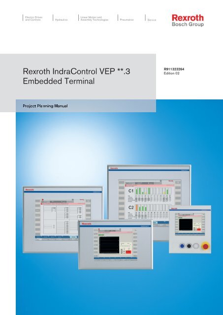
<strong>Bosch</strong> <strong>Rexroth</strong> AG | Electric Drivesand Controls<strong>Rexroth</strong> IndraControl VEP **.3 | <strong>Project</strong> <strong>Planning</strong> <strong>Manual</strong>TitleType of DocumentationDocument TypecodeInternal File ReferencePurpose of DocumentationRecord of Revision<strong>Rexroth</strong> IndraControl VEP **.3Embedded Terminal<strong>Project</strong> <strong>Planning</strong> <strong>Manual</strong>DOK-SUPPL*-<strong>VEP**.3</strong>****-PR02-EN-PRS-7f42ed884670d2580a6846a000f01abe-2-en-US-6This documentation describes the Embedded Terminals IndraControl VEP30.3, VEP 40.3 and VEP 50.3.Edition Release Date Notes120-2100-B394-01/EN 01.2008 First edition120-2100-B394-02/EN 07.2009 Second editionCopyright © <strong>Bosch</strong> <strong>Rexroth</strong> AG, 2008ValidityPublished byNoteCopying this document, giving it to others and the use or communication of thecontents thereof without express authority, are forbidden. Offenders are liablefor the payment of damages. All rights are reserved in the event of the grant ofa patent or the registration of a utility model or design (DIN 34-1).The specified data is for product description purposes only and may not bedeemed to be guaranteed unless expressly confirmed in the contract. All rightsare reserved with respect to the content of this documentation and the availabilityof the product.<strong>Bosch</strong> <strong>Rexroth</strong> AGBgm.-Dr.-Nebel-Str. 2 ■ 97816 Lohr am Main, GermanyPhone +49 (0)93 52/ 40-0 ■ Fax +49 (0)93 52/ 40-48 85http://www.boschrexroth.com/Dept. DCC/EAY2 (MK/CS)Dept. DCC/EAP1 (HP/CS)This document has been printed on chlorine-free bleached paper.
<strong>Project</strong> <strong>Planning</strong> <strong>Manual</strong> | <strong>Rexroth</strong> IndraControl VEP **.3 Electric Drivesand ControlsTable of Contents| <strong>Bosch</strong> <strong>Rexroth</strong> AG I/IVTable of Contents1 System Presentation...................................................................................................... 51.1 Short Description IndraControl VEP 30.3, IndraControl VEP 40.3 and IndraControl VEP 50.3............. 51.1.1 General Information............................................................................................................................. 51.1.2 IndraControl VEP xx.3......................................................................................................................... 51.1.3 Embedded Terminals with Touch Screen............................................................................................ 71.1.4 Front of the IndraControl VEP with Touch Screen.............................................................................. 71.2 Front of the IndraControl VEP 30.3DK with Touch Screen, 3 Buttons and Emergency Stop................. 81.3 Operating System................................................................................................................................... 81.4 Commissioning....................................................................................................................................... 82 Important Instructions on Use ....................................................................................... 92.1 Appropriate Use ..................................................................................................................................... 92.1.1 Introduction.......................................................................................................................................... 92.1.2 Areas of Use and Application.............................................................................................................. 92.2 Inappropriate Use................................................................................................................................. 10Page3 Safety Instructions for Electric Drives and Controls .................................................... 113.1 Definitions of Terms.............................................................................................................................. 113.2 General Information.............................................................................................................................. 123.2.1 Using the Safety Instructions and Passing Them on to Others......................................................... 123.2.2 Requirements for Safe Use............................................................................................................... 123.2.3 Hazards by Improper Use.................................................................................................................. 133.2.4 Explanation of Safety Symbols and Hazard Classification................................................................ 143.3 Instructions with Regard to Specific Dangers....................................................................................... 143.3.1 Protection Against Contact with Electrical Parts and Housings......................................................... 143.3.2 Protective Extra-Low Voltage as Protection Against Electric Shock ................................................ 153.3.3 Protection Against Dangerous Movements....................................................................................... 163.3.4 Protection Against Magnetic and Electromagnetic Fields During Operation and Mounting.............. 183.3.5 Protection Against Contact with Hot Parts......................................................................................... 183.3.6 Protection During Handling and Mounting......................................................................................... 193.3.7 Battery Safety.................................................................................................................................... 193.3.8 Protection Against Pressurized Systems........................................................................................... 194 Technical Data............................................................................................................. 214.1 Technical Data of the Front Panel........................................................................................................ 214.1.1 IndraControl VEP 30.3....................................................................................................................... 214.1.2 IndraControl VEP 40.3....................................................................................................................... 214.1.3 IndraControl VEP 50.3....................................................................................................................... 214.2 Technical Data of the VEP xx.3 Devices.............................................................................................. 224.3 Electrical Wiring.................................................................................................................................... 234.4 Capacitor Pack as Short-time UPS....................................................................................................... 244.5 Ambient Conditions............................................................................................................................... 244.6 Weight................................................................................................................................................... 24
II/IV<strong>Bosch</strong> <strong>Rexroth</strong> AG | Electric Drivesand Controls<strong>Rexroth</strong> IndraControl VEP **.3 | <strong>Project</strong> <strong>Planning</strong> <strong>Manual</strong>Table of ContentsPage4.7 Used Standards.................................................................................................................................... 254.7.1 Used Standards................................................................................................................................. 254.7.2 CE Marking........................................................................................................................................ 25Declaration of Conformity............................................................................................................... 25Note for the <strong>Machine</strong> Manufacturer................................................................................................ 264.7.3 UL/CSA Certified............................................................................................................................... 264.8 Wear Parts............................................................................................................................................ 264.9 Compatibility Test................................................................................................................................. 275 Dimensions.................................................................................................................. 295.1 Housing Dimensions............................................................................................................................. 295.1.1 Housing Dimensions of the IndraControl VEP 30.3CCN .................................................................. 295.1.2 Housing Dimensions of the IndraControl VEP 30.3CCU .................................................................. 305.1.3 Housing Dimensions of the IndraControl VEP 30.3DKN................................................................... 325.1.4 Housing dimensions of the IndraControl VEP 30.3DKU.................................................................... 345.1.5 Housing Dimensions of the IndraControl VEP 40.3CEN................................................................... 365.1.6 Housing Dimensions of the IndraControl VEP 40.3CEU................................................................... 385.1.7 Housing Dimensions of the IndraControl VEP 50.3CHN................................................................... 405.1.8 Housing Dimensions of the IndraControl VEP 50.3CHU................................................................... 425.2 Installation............................................................................................................................................. 445.2.1 Installation Notes............................................................................................................................... 445.2.2 Mounting Cut-out............................................................................................................................... 445.2.3 Mounting to a Standardized VESA Bracket on a VEP 30.3DK.......................................................... 445.2.4 VESA Bracket for VEP 30.3DK......................................................................................................... 455.2.5 Mounting Dimensions of the IndraControl VEP 30.3CC.................................................................... 465.2.6 Mounting Dimensions of the IndraControl VEP 30.3DK.................................................................... 475.2.7 Mounting Dimensions of the IndraControl VEP 40.3CE.................................................................... 485.2.8 Mounting Dimensions of the IndraControl VEP 50.3CH.................................................................... 496 Display and Operating Components............................................................................ 516.1 Backlight Dimming................................................................................................................................ 516.2 Touch Screen....................................................................................................................................... 517 Connection Assignments............................................................................................. 537.1 Connector Panel of the VEP Visu Device............................................................................................. 537.2 Connector Panel of the IndraLogic Device with COM Profibus Module............................................... 537.3 VEP 30.3DK IP54 Device..................................................................................................................... 537.3.1 General Information........................................................................................................................... 537.3.2 Housing of the VEP 30.3DK Device.................................................................................................. 547.3.3 Housing Cover................................................................................................................................... 567.3.4 Keypad.............................................................................................................................................. 567.3.5 Keypad Connection Scheme............................................................................................................. 567.3.6 Pin Assignment of the Keypad.......................................................................................................... 577.4 Interfaces.............................................................................................................................................. 587.4.1 General Information........................................................................................................................... 58
<strong>Project</strong> <strong>Planning</strong> <strong>Manual</strong> | <strong>Rexroth</strong> IndraControl VEP **.3 Electric Drivesand Controls| <strong>Bosch</strong> <strong>Rexroth</strong> AG III/IVTable of ContentsPage7.4.2 Overview............................................................................................................................................ 587.4.3 Serial Interface XCOM1..................................................................................................................... 597.4.4 USB Interfaces XUSB........................................................................................................................ 607.4.5 Ethernet Interfaces X7E1 and X7E2.................................................................................................. 607.4.6 24 VDC Voltage Supply XS1............................................................................................................. 617.4.7 Fieldbus Module................................................................................................................................ 62Profibus Interfaces X7P.................................................................................................................. 62Technical Data of the Profibus Master Interface............................................................................ 62Status Displays and Diagnostics Displays of the Profibus Master................................................. 628 Maintenance and Installation....................................................................................... 638.1 General Information.............................................................................................................................. 638.2 LCD Display.......................................................................................................................................... 638.3 CMOS Battery....................................................................................................................................... 639 Software....................................................................................................................... 659.1 General Information.............................................................................................................................. 659.2 First Commissioning............................................................................................................................. 659.3 Touch Calibration.................................................................................................................................. 669.4 <strong>Rexroth</strong> CE Settings............................................................................................................................. 669.4.1 General Information........................................................................................................................... 669.4.2 <strong>Rexroth</strong> CE Settings - Ethernet Adapter............................................................................................ 67General Information........................................................................................................................ 679.4.3 <strong>Rexroth</strong> CE Settings - Application Settings....................................................................................... 67General Information........................................................................................................................ 67Visualization................................................................................................................................... 68UDP Real-time Data Transmission................................................................................................. 68Visualization Data Source.............................................................................................................. 689.4.4 <strong>Rexroth</strong> CE Settings - Data Server.................................................................................................... 68General Information........................................................................................................................ 689.4.5 <strong>Rexroth</strong> CE Settings - System Info.................................................................................................... 69General Information........................................................................................................................ 699.5 Windows CE 4.2 .NET.......................................................................................................................... 709.5.1 General Information........................................................................................................................... 709.5.2 Operation........................................................................................................................................... 70Touch Screen Operation................................................................................................................ 70Text Input via Virtual Keyboard ..................................................................................................... 719.5.3 Memory Distribution........................................................................................................................... 719.5.4 USB Support...................................................................................................................................... 729.5.5 Microsoft Programs........................................................................................................................... 73General Information........................................................................................................................ 73Microsoft File Viewer...................................................................................................................... 73Further Microsoft Programs............................................................................................................ 73Further Desktop Icons ................................................................................................................... 739.5.6 FTP Server........................................................................................................................................ 74
IV/IV<strong>Bosch</strong> <strong>Rexroth</strong> AG | Electric Drivesand Controls<strong>Rexroth</strong> IndraControl VEP **.3 | <strong>Project</strong> <strong>Planning</strong> <strong>Manual</strong>Table of ContentsPage9.5.7 Web Server........................................................................................................................................ 749.5.8 Telnet Server..................................................................................................................................... 749.5.9 CE User Configuration....................................................................................................................... 749.6 IndraLogicWinCE.................................................................................................................................. 749.7 WinStudio............................................................................................................................................. 759.7.1 General Information........................................................................................................................... 759.7.2 Remote Agent - Setup....................................................................................................................... 7610 Environmental Protection and Disposal ...................................................................... 7910.1 Environmental Protection...................................................................................................................... 7910.2 Disposal................................................................................................................................................ 7911 Ordering Information.................................................................................................... 8111.1 Type Designation Code........................................................................................................................ 8111.1.1 General Information........................................................................................................................... 8111.1.2 IndraControl VEP 30.3....................................................................................................................... 8111.1.3 IndraControl VEP 40.3....................................................................................................................... 8211.1.4 IndraControl VEP 50.3....................................................................................................................... 8311.2 Accessories.......................................................................................................................................... 8411.2.1 Plugs and Assembled Cables............................................................................................................ 8411.2.2 Storage Media................................................................................................................................... 8412 Service and Support.................................................................................................... 85Index............................................................................................................................ 87
<strong>Project</strong> <strong>Planning</strong> <strong>Manual</strong> | <strong>Rexroth</strong> IndraControl VEP **.3 Electric Drivesand Controls| <strong>Bosch</strong> <strong>Rexroth</strong> AG 5/89System Presentation1 System Presentation1.1 Short Description IndraControl VEP 30.3, IndraControlVEP 40.3 and IndraControl VEP 50.31.1.1 General Information1.1.2 IndraControl VEP xx.3The IndraControl VEP 30.3, VEP 40.3 and VEP 50.3 Embedded Terminals arePC based machine operator terminals. Depending on the respective applicationor configiruation they can also perform control functions.In this documentation the Embedded Terminals IndraControlVEP 30.3, VEP 40.3 and VEP 50.3 are named as IndraControlVEP xx.3.The IndraControl VEP xx.3 Embedded Terminals are available in different variants.They differ only in the display size and in the different design of the PCbox.VEP xx.3 variant treeProcessor/memoryDevicesDegreeofprotectionDisplayFrontOrder number and type designationcodeVISU IP 20600 MHz /256 MB8.4"TouchscreenR911170849VEP30.3CCN-256NN-MAD-128-NN-FW12"TouchscreenR911170850VEP40.3CEN-256NN-MAD-128-NN-FW15"TouchscreenR911170851VEP50.3CHN-256NN-MAD-128-NN-FWTouch/VISU IP 54600 MHz /256 MB8.4"3 buttons/EmergencystopR911171626VEP30.3DKN-256NN-MAD-128-CG-FWIndraLogicIP 20600 MHz /256 MB8.4"TouchscreenR911170853VEP30.3CCU-256NA-MAD-128-NN-FW
6/89 <strong>Bosch</strong> <strong>Rexroth</strong> AG | Electric Drivesand Controls<strong>Rexroth</strong> IndraControl VEP **.3 | <strong>Project</strong> <strong>Planning</strong> <strong>Manual</strong>System PresentationProcessor/memoryDevicesDegreeofprotectionDisplayFrontOrder number and type designationcode12"TouchscreenR911170854VEP40.3CEU-256NA--128-NN-FWMAD15"TouchscreenR911170855VEP50.3CHU-256NA-MAD-128-NN-FWTouch/IndraLogicIP 54600 MHz /256 MB8.4"3 buttons/EmergencystopR911170860VEP30.3DKU-256NN-MAD-128-CG-FWDifferent display sizesFig.1-1:VEP xx.3 variant treeVEP 30.3CCDisplay8.4" TFTTouch screenYesButtonsNoFig.1-2:Front of the IndraControl VEP 30.3CCVEP 30.3DKDisplay8.4" TFTTouch screenYesButtonsFig.1-3:Front of the IndraControl VEP 30.3DK3 buttons / 1 emergency stop pushbuttonVEP 40.3CEDisplayTouch screenButtons12.1" TFTYesNoFig.1-4: Front of the IndraControl VEP 40.3VEP 50.3CHDisplayTouch screenButtons15" TFTYesNoDifferent PC boxesFig.1-5: Front of the IndraControl VEP 50.3The IndraControl VEP xx.3 devices are equipped with different PC boxes.The PC boxes differ according to the application:
<strong>Project</strong> <strong>Planning</strong> <strong>Manual</strong> | <strong>Rexroth</strong> IndraControl VEP **.3 Electric Drivesand Controls| <strong>Bosch</strong> <strong>Rexroth</strong> AG 7/89System PresentationVEP xx.3 Visu ● Celeron 600 MHz●●●●min. 256 MB RAMan Ethernet interfacewithout fieldbuswithout short-time UPSVEP xx.3 Indra Logic ● Celeron 600 MHz●●●●min. 256 MB RAM2 Ethernet interfaces1 COM fieldbus modulewith short-time UPSPower unit of the PC boxesFig.1-6:Different PC boxesAll PC boxes are provided with a 24 V power supply unit and can be connectedto an external UPS. The PC boxes are only cooled passively. An external fanconnection for a 12 V fan is provided, however is not required in the specifiedtemperature range (see also chapter 4.5 "Ambient Conditions" on page 24).Voltage and internal temperature are monitored. In case of error, the device isswitched off to prevent the destruction of the electronic components.1.1.3 Embedded Terminals with Touch ScreenThe front panel with touch screen allows to operate the application software viathe touch-sensitive surface of the display without keyboard and mouse.1.1.4 Front of the IndraControl VEP with Touch ScreenFig.1-7:Front of the IndraControl VEP
8/89 <strong>Bosch</strong> <strong>Rexroth</strong> AG | Electric Drivesand Controls<strong>Rexroth</strong> IndraControl VEP **.3 | <strong>Project</strong> <strong>Planning</strong> <strong>Manual</strong>System Presentation1.2 Front of the IndraControl VEP 30.3DK with Touch Screen, 3Buttons and Emergency StopFig.1-8:Front of the IndraControl VEP 30.3DK1.3 Operating System1.4 CommissioningFor license reasons the devices of the IndraControl VEP xx.3 type are onlydelivered with already installed operating system. For further information aboutthe operating system please refer to chapter 9 "Software" on page 65.Mount the device properly (see chapter 5 "Dimensions" on page 29). Thenconnect the device to the power supply and, if required, to the network.
<strong>Project</strong> <strong>Planning</strong> <strong>Manual</strong> | <strong>Rexroth</strong> IndraControl VEP **.3 Electric Drivesand Controls| <strong>Bosch</strong> <strong>Rexroth</strong> AG 9/89Important Instructions on Use2 Important Instructions on Use2.1 Appropriate Use2.1.1 Introduction<strong>Rexroth</strong> products represent state-of-the-art developments and manufacturing.They are tested prior to delivery to ensure operational safety and reliability.WARNINGPhysical injury and material damage might result from an inappropriateuse of the products!The products are designed for the use in an industrial environment and maytherefore only be used for the intended purpose. If they are not used as intended,situations causing personal injury as well as material damage can occur.2.1.2 Areas of Use and Application<strong>Rexroth</strong> disclaims as manufacturer any warranty, liability or damagesoccurring due to inappropriate use of the products. Furthermore,<strong>Rexroth</strong> is not paying any compensation. The user isresponsible for any risks resulting from inappropriate use of theproducts.Before using <strong>Rexroth</strong> products, the following requirements must be met to ensureappropriate use of the products:●●●●Anyone handling one of the <strong>Rexroth</strong> products in any way has to read andunderstand the respective safety-related guidelines as well as the instructionson appropriate use.Hardware products have to remain in their original state, i. e. no modificationregarding the design is allowed. Software products must not bedecompiled and their source codes must not be modified.Damaged or faulty products must not be implemented or put into operation.It must be ensured that the products are installed as specified in the documentation.The VEP xx.3 Embedded Terminals are PC based machine operator terminals.Depending on the respective application or configuration they also can performcontrol functionalities.It can be necessary to connect additional sensors and actuators to control andmonitor the VEP xx.3.The VEP xx.3 may only be used with the accessories and add-oncomponents specified in this documentation. Components notnamed expressly mentioned must neither be mounted nor connected.The same applies to cables and conduits.The products may only be operated with the expressly stated configurationsand component combinations as well as with the softwareand firmware which given and specified in the respectivefunctional description.Each drive control device has to be programmed before commissioning so thatthe motor executes the application-specific functions.
<strong>Project</strong> <strong>Planning</strong> <strong>Manual</strong> | <strong>Rexroth</strong> IndraControl VEP **.3 Electric Drivesand Controls| <strong>Bosch</strong> <strong>Rexroth</strong> AG 11/89Safety Instructions for Electric Drives and Controls3 Safety Instructions for Electric Drives and Controls3.1 Definitions of TermsApplication DocumentationComponentControl SystemDeviceDrive SystemElectrical EquipmentInstallation<strong>Machine</strong>ManufacturerProduct<strong>Project</strong> <strong>Planning</strong> <strong>Manual</strong>Qualified PersonsThe entire documentation used to inform the user of the product about the useand safety-relevant features for configuring, integrating, installing, mounting,commissioning, operating, maintaining, repairing and decommissioning theproduct. The following terms are also used for this kind of documentation: UserGuide, Operation <strong>Manual</strong>, Commissioning <strong>Manual</strong>, Instruction <strong>Manual</strong>, <strong>Project</strong><strong>Planning</strong> <strong>Manual</strong>, Application <strong>Manual</strong>, etc.Combination of elements with a specified function, which are part of a piece ofequipment, device or system. Components of a drive and control system are,for example, supply units, drive controllers, mains choke, mains filter, motors,cables, etc.Several interconnected control components placed on the market as a singlefunctional unit.Finished product with a defined function, intended for users and placed on themarket as an individual piece of merchandise.A group of components consisting of electric motor(s), motor encoder(s) andcable(s), supply units and drive controllers, as well as possible auxiliary andadditional components, such as mains filter, mains choke, etc.Objects used to generate, convert, transmit, distribute or apply electrical energy,such as machines, transformers, switching devices, cables, lines, powerconsumingdevices, circuit board assemblies, plug-in units, control cabinets,etc.Several devices or systems interconnected for a defined purpose and on a definedsite which, however, are not intended to be placed on the market as asingle functional unit.Entirety of interconnected parts or units at least one of which is movable. Thus,a machine consists of the appropriate machine drive elements, as well as controland power circuits, which have been assembled for a specific application.A machine is, for example, intended for processing, treatment, movement orpackaging of a material. The term "machine" also covers a combination of machineswhich are arranged and controlled in such a way that they function as aunified whole.Individual or legal entity bearing responsibility for the design and manufactureof a product which is placed on the market in the individual's or legal entity'sname. The manufacturer can use finished products, finished parts or finishedelements, or contract out work to subcontractors. However, he must alwayshave overall control and possess the required authority to take responsibilityfor the product.Produced device, component, part, system, software, firmware, among otherthings.Part of the application documentation used to support the dimensioning andplanning of systems, machines or installations.In terms of this application documentation, qualified persons are those personswho are familiar with the installation, mounting, commissioning and operationof the components of the drive and control system, as well as with the hazardsthis implies, and who possess the qualifications their work requires. To complywith these qualifications, it is necessary, among other things,●to be trained, instructed or authorized to switch electric circuits and devicessafely on and off, to ground them and to mark them,
12/89 <strong>Bosch</strong> <strong>Rexroth</strong> AG | Electric Drivesand Controls<strong>Rexroth</strong> IndraControl VEP **.3 | <strong>Project</strong> <strong>Planning</strong> <strong>Manual</strong>Safety Instructions for Electric Drives and ControlsUser●●to be trained or instructed to maintain and use adequate safety equipment,to attend a course of instruction in first aid.A person installing, commissioning or using a product which has been placedon the market.3.2 General Information3.2.1 Using the Safety Instructions and Passing Them on to OthersDo not attempt to install and operate the electric components of the drive andcontrol system without first reading all documentation provided with the product.Read and understand these safety instructions and all user documentation priorto working with these components. If you do not have the user documentationfor the components, contact your responsible <strong>Bosch</strong> <strong>Rexroth</strong> sales partner. Askfor these documents to be sent immediately to the person or persons responsiblefor the safe operation of the components.If the component is resold, rented and/or passed on to others in any other form,these safety instructions must be delivered with the component in the officiallanguage of the user's country.WARNINGImproper use of these components, failure to follow the safety instructionsin this document or tampering with the product, including disablingof safety devices, could result in property damage, injury, electric shockor even death.Observe the safety instructions!3.2.2 Requirements for Safe UseRead the following instructions before initial commissioning of the electric componentsof the drive and control system in order to eliminate the risk of injuryand/or property damage. You must follow these safety instructions.●●●●●●●●●<strong>Bosch</strong> <strong>Rexroth</strong> is not liable for damages resulting from failure to observethe safety instructions.Read the operating, maintenance and safety instructions in your languagebefore commissioning. If you find that you cannot completely understandthe application documentation in the available language, please ask yoursupplier to clarify.Proper and correct transport, storage, mounting and installation, as wellas care in operation and maintenance, are prerequisites for optimal andsafe operation of the component.Only qualified persons may work with components of the drive and controlsystem or within its proximity.Only use accessories and spare parts approved by <strong>Bosch</strong> <strong>Rexroth</strong>.Follow the safety regulations and requirements of the country in which theelectric components of the drive and control system are operated.Only use the components of the drive and control system in the mannerthat is defined as appropriate. See chapter "Appropriate Use".The ambient and operating conditions given in the application documentationat hand must be observed.Safety-relevant applications are only allowed if clearly and explicitly specifiedin the application documentation "Integrated Safety Technology". If
<strong>Project</strong> <strong>Planning</strong> <strong>Manual</strong> | <strong>Rexroth</strong> IndraControl VEP **.3 Electric Drivesand Controls| <strong>Bosch</strong> <strong>Rexroth</strong> AG 13/89Safety Instructions for Electric Drives and Controls●●●●●this is not the case, they are excluded. Safety-relevant are all such applicationswhich can cause danger to persons and property damage.The information given in the application documentation with regard to theuse of the delivered components contains only examples of applicationsand suggestions.The machine and installation manufacturer must– make sure that the delivered components are suited for his individualapplication and check the information given in this application documentationwith regard to the use of the components,– make sure that his individual application complies with the applicablesafety regulations and standards and carry out the required measures,modifications and complements.Commissioning of the delivered components is only allowed once it is surethat the machine or installation in which the components are installedcomplies with the national regulations, safety specifications and standardsof the application.Operation is only allowed if the national EMC regulations for the applicationare met.The instructions for installation in accordance with EMC requirements canbe found in the section on EMC in the respective application documentation.The machine or installation manufacturer is responsible for compliancewith the limit values as prescribed in the national regulations.The technical data, connection and installation conditions of the componentsare specified in the respective application documentations and mustbe followed at all times.National regulations which the user must take into account●●●●European countries: According to European EN standardsUnited States of America (USA):– National Electrical Code (NEC)– National Electrical Manufacturers Association (NEMA), as well aslocal engineering regulations– Regulations of the National Fire Protection Association (NFPA)Canada: Canadian Standards Association (CSA)Other countries:– International Organization for Standardization (ISO)– International Electrotechnical Commission (IEC)3.2.3 Hazards by Improper Use●●●●●High electrical voltage and high working current! Danger to life or seriousinjury by electric shock!High electrical voltage by incorrect connection! Danger to life or injury byelectric shock!Dangerous movements! Danger to life, serious injury or property damageby unintended motor movements!Health hazard for persons with heart pacemakers, metal implants andhearing aids in proximity to electric drive systems!Risk of burns by hot housing surfaces!
14/89 <strong>Bosch</strong> <strong>Rexroth</strong> AG | Electric Drivesand Controls<strong>Rexroth</strong> IndraControl VEP **.3 | <strong>Project</strong> <strong>Planning</strong> <strong>Manual</strong>Safety Instructions for Electric Drives and Controls●●●Risk of injury by improper handling! Injury by crushing, shearing, cutting,hitting!Risk of injury by improper handling of batteries!Risk of injury by improper handling of pressurized lines!3.2.4 Explanation of Safety Symbols and Hazard ClassificationThe safety instructions describe the following hazard classification. The hazardclassification informs about the consequences resulting from non-compliancewith the safety instructions:Safety symbolSignalwordDangerHazard classification according to ANSI Z535.4-2002Death or serious injury will occur.WarningDeath or serious injury could occur.CautionMinor or moderate injury or property damage may occur.Fig.3-1:Hazard classification (according to ANSI Z535.4-2002)3.3 Instructions with Regard to Specific Dangers3.3.1 Protection Against Contact with Electrical Parts and HousingsThis section concerns components of the drive and control systemwith voltages of more than 50 volts.Contact with parts conducting voltages above 50 volts can cause personaldanger and electric shock. When operating components of the drive and controlsystem, it is unavoidable that some parts of these components conduct dangerousvoltage.
<strong>Project</strong> <strong>Planning</strong> <strong>Manual</strong> | <strong>Rexroth</strong> IndraControl VEP **.3 Electric Drivesand Controls| <strong>Bosch</strong> <strong>Rexroth</strong> AG 15/89Safety Instructions for Electric Drives and ControlsWARNINGWARNINGHigh electrical voltage! Danger to life, risk of injury by electric shock orserious injury!●●●●Only qualified persons are allowed to operate, maintain and/or repair theelectric components of the drive and control system.Follow the general installation and safety regulations when working onpower installations.Before switching on, the equipment grounding conductor must have beenpermanently connected to all electric components in accordance with theconnection diagram.Even for brief measurements or tests, operation is only allowed if theequipment grounding conductor has been permanently connected to thepoints of the components provided for this purpose.● Before accessing electrical parts with voltage potentials higher than 50 V,you must disconnect electric components from the mains or from the powersupply unit. Secure the electric component from reconnection.●●●●●●With electric components, observe the following aspects:Always wait 30 minutes after switching off power to allow live capacitorsto discharge before accessing an electric component. Measure the electricalvoltage of live parts before beginning to work to make sure that theequipment is safe to touch.Install the covers and guards provided for this purpose before switchingon.Never touch electrical connection points of the components while poweris turned on.Do not remove or plug in connectors when the component has been powered.As a basic principle, residual-current-operated circuit-breakers cannot beused for electric drives to prevent direct contact.Secure built-in devices from penetrating foreign objects and water, as wellas from direct contact, by providing an external housing, for example acontrol cabinet.High housing voltage and high leakage current! Danger to life, risk ofinjury by electric shock!●●●Before switching on and before commissioning, ground or connect thecomponents of the drive and control system to the equipment groundingconductor at the grounding points.Connect the equipment grounding conductor of the components of thedrive and control system permanently to the main power supply at alltimes. The leakage current is greater than 3.5 mA.Establish an equipment grounding connection with a copper wire of across section of at least 10 mm 2 (8 AWG) or additionally run a secondequipment grounding conductor of the same cross section as the originalequipment grounding conductor.3.3.2 Protective Extra-Low Voltage as Protection Against Electric ShockProtective extra-low voltage is used to allow connecting devices with basic insulationto extra-low voltage circuits.All connections and terminals with voltages between 5 and 50 volts at the componentsof the <strong>Bosch</strong> <strong>Rexroth</strong> drive and control system are PELV ("ProtectiveExtra-Low Voltage") systems. It is allowed to connect devices equipped
<strong>Project</strong> <strong>Planning</strong> <strong>Manual</strong> | <strong>Rexroth</strong> IndraControl VEP **.3 Electric Drivesand Controls| <strong>Bosch</strong> <strong>Rexroth</strong> AG 17/89Safety Instructions for Electric Drives and ControlsWARNINGDangerous movements! Danger to life, risk of injury, serious injury orproperty damage!●A risk assessment must be prepared for the installation or machine, withits specific conditions, in which the components of the drive and controlsystem are installed. As a result of the risk assessment, the user mustprovide for monitoring functions and higher-level measures on the installationside for personal safety. The safety regulations applicable to theinstallation or machine must be taken into consideration. Unintended machinemovements or other malfunctions are possible if safety devices aredisabled, bypassed or not activated.To avoid accidents, injury and/or property damage:●●●●●●●●●Keep free and clear of the machine’s range of motion and moving machineparts. Prevent personnel from accidentally entering the machine’s rangeof motion by using, for example:– Safety fences– Safety guards– Protective coverings– Light barriersMake sure the safety fences and protective coverings are strong enoughto resist maximum possible kinetic energy.Mount emergency stop switches in the immediate reach of the operator.Before commissioning, verify that the emergency stop equipment works.Do not operate the machine if the emergency stop switch is not working.Prevent unintended start-up. Isolate the drive power connection by meansof an emergency stop circuit or use a safe starting lockout.Make sure that the drives are brought to a safe standstill before accessingor entering the danger zone.Additionally secure vertical axes against falling or dropping after switchingoff the motor power by, for example,– mechanically securing the vertical axes,– adding an external braking/arrester/clamping mechanism or– ensuring sufficient equilibration of the vertical axes.The standard equipment motor holding brake or an external holding brakecontrolled by the drive controller is not sufficient to guarantee personalsafety!Disconnect electrical power to the components of the drive and controlsystem using the master switch and secure them from reconnection for:– Maintenance and repair work– Cleaning of equipment– Long periods of discontinued equipment usePrevent the operation of high-frequency, remote control and radio equipmentnear electric/electronic components of the drive and control systemand their supply leads. If the use of these devices cannot be avoided,check the machine or installation, before initial commissioning of the driveand control system, for possible malfunctions when operating such highfrequency,remote control and radio equipment in its possible positions ofnormal use. It might possibly be necessary to perform a special electromagneticcompatibility (EMC) test.
18/89 <strong>Bosch</strong> <strong>Rexroth</strong> AG | Electric Drivesand Controls<strong>Rexroth</strong> IndraControl VEP **.3 | <strong>Project</strong> <strong>Planning</strong> <strong>Manual</strong>Safety Instructions for Electric Drives and Controls3.3.4 Protection Against Magnetic and Electromagnetic Fields During Operationand MountingMagnetic and electromagnetic fields generated by current-carrying conductorsor permanent magnets of electric motors represent a serious danger to personswith heart pacemakers, metal implants and hearing aids.WARNINGHealth hazard for persons with heart pacemakers, metal implants andhearing aids in proximity to electric components!●●●Persons with heart pacemakers and metal implants are not allowed toenter the following areas:– Areas in which components of the drive and control systems aremounted, commissioned and operated.– Areas in which parts of motors with permanent magnets are stored,repaired or mounted.If it is necessary for somebody with a heart pacemaker to enter such anarea, a doctor must be consulted prior to doing so. The noise immunity ofimplanted heart pacemakers differs greatly so that no general rules canbe given.Those with metal implants or metal pieces, as well as with hearing aids,must consult a doctor before they enter the areas described above.3.3.5 Protection Against Contact with Hot PartsCAUTIONHot surfaces of components of the drive and control system. Risk ofburns!●●●●●●Do not touch hot surfaces of, for example, braking resistors, heat sinks,supply units and drive controllers, motors, windings and laminated cores!According to the operating conditions, temperatures of the surfaces canbe higher than 60 °C (140 °F) during or after operation.Before touching motors after having switched them off, let them cool downfor a sufficiently long time. Cooling down can require up to 140 minutes!The time required for cooling down is approximately five times the thermaltime constant specified in the technical data.After switching chokes, supply units and drive controllers off, wait 15 minutesto allow them to cool down before touching them.Wear safety gloves or do not work at hot surfaces.For certain applications and according to the respective safety regulations,the manufacturer of the machine or installation has to take measures toavoid injuries caused by burns in the end application. These measurescan be, for example: Warnings at the machine or installation, guards(shieldings or barriers) or safety instructions in the application documentation.
<strong>Project</strong> <strong>Planning</strong> <strong>Manual</strong> | <strong>Rexroth</strong> IndraControl VEP **.3 Electric Drivesand Controls| <strong>Bosch</strong> <strong>Rexroth</strong> AG 19/89Safety Instructions for Electric Drives and Controls3.3.6 Protection During Handling and MountingCAUTIONRisk of injury by improper handling! Injury by crushing, shearing, cutting,hitting!●●●●●●●●Observe the relevant statutory regulations of accident prevention.Use suitable equipment for mounting and transport.Avoid jamming and crushing by appropriate measures.Always use suitable tools. Use special tools if specified.Use lifting equipment and tools in the correct manner.Use suitable protective equipment (hard hat, safety goggles, safety shoes,safety gloves, for example).Do not stand under hanging loads.Immediately clean up any spilled liquids from the floor due to the risk ofslipping.3.3.7 Battery SafetyBatteries consist of active chemicals in a solid housing. Therefore, improperhandling can cause injury or property damage.CAUTIONRisk of injury by improper handling!●●●●●●Do not attempt to reactivate low batteries by heating or other methods (riskof explosion and cauterization).Do not attempt to recharge the batteries as this may cause leakage orexplosion.Do not throw batteries into open flames.Do not dismantle batteries.When replacing the battery/batteries, do not damage the electrical partsinstalled in the devices.Only use the battery types specified for the product.Environmental protection and disposal! The batteries contained inthe product are considered dangerous goods during land, air, andsea transport (risk of explosion) in the sense of the legal regulations.Dispose of used batteries separately from other waste. Observe thenational regulations of your country.3.3.8 Protection Against Pressurized SystemsAccording to the information given in the <strong>Project</strong> <strong>Planning</strong> <strong>Manual</strong>s, motors andcomponents cooled with liquids and compressed air can be partially suppliedwith externally fed, pressurized media, such as compressed air, hydraulics oil,cooling liquids and cooling lubricants. Improper handling of the connected supplysystems, supply lines or connections can cause injuries or property damage.
20/89 <strong>Bosch</strong> <strong>Rexroth</strong> AG | Electric Drivesand Controls<strong>Rexroth</strong> IndraControl VEP **.3 | <strong>Project</strong> <strong>Planning</strong> <strong>Manual</strong>Safety Instructions for Electric Drives and ControlsWARNINGRisk of injury by improper handling of pressurized lines!●●●●●Do not attempt to disconnect, open or cut pressurized lines (risk of explosion).Observe the respective manufacturer's operating instructions.Before dismounting lines, relieve pressure and empty medium.Use suitable protective equipment (safety goggles, safety shoes, safetygloves, for example).Immediately clean up any spilled liquids from the floor due to the risk ofslipping.Environmental protection and disposal! The agents (e.g., fluids)used to operate the product might not be environmentally friendly.Dispose of agents harmful to the environment separately from otherwaste. Observe the national regulations of your country.
<strong>Project</strong> <strong>Planning</strong> <strong>Manual</strong> | <strong>Rexroth</strong> IndraControl VEP **.3 Electric Drivesand Controls| <strong>Bosch</strong> <strong>Rexroth</strong> AG 21/89Technical Data4 Technical Data4.1 Technical Data of the Front Panel4.1.1 IndraControl VEP 30.3VEP 30.3CCVEP 30.3DKDisplay8.4" TFT, 800 x 600 pixels, 262,144 colorsOperationSurface − Front panelTouch screen operationColor RAL 7035 light grayTouch screen operation, 3buttons and emergencystopDegree of protection, frontpanelDegree of protection, totaldeviceIP 65 acc. to DIN 40 050, IEC 529.Front type 1 according to NEMA (UL)IP 20 IP 544.1.2 IndraControl VEP 40.3Fig.4-1: Technical data, front panel of the IndraControl VEP 30.3VEP 40.3CEDisplayOperationSurface − Front panel12.1" TFT, 800 x 600 pixels, 262,144 colorsTouch screen operationColor RAL 7035 light gray4.1.3 IndraControl VEP 50.3Degree of protection Front panel IP 65 acc. to DIN 40 050, IEC 529Front type 1 according to NEMA (UL)whole device IP 20 (VEP 40.3CE)Fig.4-2: Technical data, front panel of the IndraControl VEP 40.3VEP 50.3CHDisplayOperationSurface – front panel15”-TFT, 1024x768 pixels,262,144 colorsTouch screen operationColor RAL 7035 light grayDegree of protection Front panel IP 65 acc. to DIN 40 050, IEC 529Front type 1 according to NEMA (UL)whole device IP 20 (VEP 50.3CH)Fig.4-3: Technical data, front panel of the IndraControl VEP 50.3
22/89 <strong>Bosch</strong> <strong>Rexroth</strong> AG | Electric Drivesand Controls<strong>Rexroth</strong> IndraControl VEP **.3 | <strong>Project</strong> <strong>Planning</strong> <strong>Manual</strong>Technical Data4.2 Technical Data of the VEP xx.3 DevicesPC box VISU IndraLogicProcessorRAMCompact Flash CardIntel Ultra Low Voltage Celeron 600 MHz,Integrated graphics controllermin. 256 MBmin. 128 MB, two slots●2 x USB 2.0 connection(type A)●2 x USB 2.0 connection(type A)Interfaces(available in all variants)●●1 x Ethernet connection(RJ 45, 10/100Base-T)1 x serial standard interfaceRS232 (9-pin,D-Sub)●●2 x Ethernet connection(RJ 45, 10/100Base-T)1 x serial standard interfaceRS232 (9-pin,D-Sub)SlotsShort-time UPSVoltage supplyNo module equippedNo short-time UPS24 VDCFieldbus interface moduleequippedCapacitor pack as shorttimeUPSInput voltage range 24 VDC (+19 V to +30 V)Emitted interference andsurge immunityMax. input currentMax. inrush current:Max. power consumptionfor maximum configurationU max = 35 V (for t < 100 ms)1.5 A7 A / 6 ms36 WFig.4-4:Technical data, PC box of the IndraControl VEP xx.3 devicesDANGERDanger without protective separation!The 24 VDC input voltage must comply with the requirements of the "Protectiveseparation"!Plug and unplug the connector only if there is no voltage!Interfering AC voltage components such as the ones resulting from an uncontrolledthree-phase bridge circuit without smoothing and with a ripple factor (seeDIN 40110/10.75, section 1.2) of 5 % are allowed.That results in the greatest absolute value of 30.2 V as upper voltage limit. Thelowest absolute value of 18.5 V is the lower voltage limit.
<strong>Project</strong> <strong>Planning</strong> <strong>Manual</strong> | <strong>Rexroth</strong> IndraControl VEP **.3 Electric Drivesand Controls| <strong>Bosch</strong> <strong>Rexroth</strong> AG 23/89Technical Data4.3 Electrical WiringWiring 230 VleadsU1 L1V1 L2W1 L3N Nmin. 16 mm² (green/yellow)16 mm² (green/yellow)6 mm² (green/yellow)PE PEPEPEPEPEPE neutral pointto the housing of the control cabinetto the deviceall housing parts (functional earth)16 mm² (green/yellow)N-conductor:Use only withpermission ofthe operator!L1.1L2.1L3.1NPEe.g. drivesFuses, better: protective motor switches400V 4 mm² (green/yellow)Transformeracc. to EN60742 230V4 mm² (green/yellowPE N U2PE (1)PEN1U24 mm² (green/yellow)230 V power supplyoperator terminalsservice plug receptacle(s)Overvoltagecategory IIIOvervoltagecategory IITerminals inisolatedarrangementPower unitVAP01.1H-W23024-010-NNOvervoltagecategory I24 VDC+24 VLength max. 4 m0 V(1) PE bars are to be installed preferably on the mounting plate.In case of isolated PE bars, both ends must be connected to the mounting plateby means of copper strips with a maximum length of 20 cm.The cross-section of the copper strips has to be at least equal to that of the incoming mains cable.Wiring 400 VFig.4-5:Wiring 230 VleadsU1 L1V1 L2W1 L3N Nmin. 16 mm² (green/yellow)16 mm² (green/yellow)6 mm² (green/yellow)PE PEPEPEPEPEPE neutral pointto the housing of the control cabinetto the deviceall housing parts (functional earth)16 mm² (green/yellow)N conductor:Use only withpermission ofthe operator!L1.1L2.1L3.1NPEe.g.drivesFuses, better: protective motor switches400V 4 mm² (green/yellow)Transformeracc. to EN 60742 230V4 mm² (green/yellow)PE N U2PE (1)4 mm² (green/yellow)Overvoltagecategory IIIPEN1U2Overvoltagecategory IIL1.1L2.1L3.1PE230 V supplyoperator terminalsservice plug receptacle(s)Power unitOvervoltagecategory I=Terminals inisolated arrangement(1) PE bars are to be installed preferably on the mounting plate.In case of isolated PE bars, both ends must be connected to the mounting plateby means of copper strips with a maximum length of 20 cm.The cross-section of the copper strips has to be at least equal to that of the incoming mains cable.24 VDC+24 V0 VFig.4-6:Wiring 400 V
24/89 <strong>Bosch</strong> <strong>Rexroth</strong> AG | Electric Drivesand Controls<strong>Rexroth</strong> IndraControl VEP **.3 | <strong>Project</strong> <strong>Planning</strong> <strong>Manual</strong>Technical Data4.4 Capacitor Pack as Short-time UPS4.5 Ambient ConditionsThe short-time UPS consists of a capacitor pack, which is installed in the PCbox, and the pending charging circuit in the power supply area of the carrierboard. The short-time UPS supplies the device for a certain time with voltage,whenthe 24 V voltage supply fails. In this time remanent data is safelystored on the Compact Flash card.The short-time UPS is only installed in IndracLogic devices!In operation Transport StorageMax. surrounding airtemperature+5 °C up to +45 °C -20 °C up to +60 °C -20 °C up to +60 °CMax. temperature gradientTemporal temperature changesup to 3 K per minuteTemporal temperature changesup to 3 K per minuteTemporal temperature changesup to 3 K per minuteHumidity Min. relative humidity: 5 %Max. relative humidity: 85%Min. absolute humidity: 1 g/m 3Max. absolute humidity: 25 g/m 3Condensation not allowedCorresponds to climatic class3K3 acc. to EN 60721-3-3Min. relative humidity: 5 %Max. relative humidity: 75%Min. absolute humidity: 1 g/m 3Max. absolute humidity: 25 g/m 3Condensation not allowedCorresponds to climatic class2K2 acc. to EN 60721-3-2Min. relative humidity: 5 %Max. relative humidity: 85%Min. absolute humidity: 1 g/m 3Max. absolute humidity: 25 g/m 3Condensation not allowedCorresponds to climatic class1K2 acc. to EN 60721-3-1Air pressureUp to 2000 m above sea levelacc. to EN 61131-2Up to 3000 m above sea levelacc. to EN 61131-2Up to 3000 m above sea levelacc. to EN 61131-2Mechanical strengthMax. vibration:Max. shock:Max. shock:Frequency range: 10...150 Hz15 g 11 ms15 g 11 msExcursion: 0.075 mm for 10 ... 57HzAcceleration: 1 g for 57 ... 150 Hzacc. to EN 60068-2-27No breakdown of the functionacc. to EN 60068-2-27No breakdown of the functionacc. to EN 600068-2-6Degree of pollution 2 2 2Overvoltage category 2 - -Fig.4-7:Ambient Conditions4.6 WeightVEP 30.3CCVEP 40.3VEP 50.3VEP 30.3DKFig.4-8:Approx. 2.3 kgApprox. 3.8 kgApprox. 5.4 kgApprox. 4.5 kgWeight of IndraControl VEP xx.3 devices
<strong>Project</strong> <strong>Planning</strong> <strong>Manual</strong> | <strong>Rexroth</strong> IndraControl VEP **.3 Electric Drivesand Controls| <strong>Bosch</strong> <strong>Rexroth</strong> AG 25/89Technical Data4.7 Used Standards4.7.1 Used StandardsThe system components of the Embedded Terminals IndraControl VEP xx.3 comply with the following standards:StandardEN 60 61000-6-4EN 60 61000-6-2EN 61558-2-6EN 60664-1EN 61 131-2ISO 13850EN 60 529EN 60 068-2-6EN 60068-2-27EN 60721-3-3EN 60721-3-2EN 60721-3-1UL 508MeaningGeneric standard, emitted interference (industrial environment)Generic standard, noise immunity (industrial environment)Transformer for 24 V power supply unit, protective separationOvervoltage category IIRequirements on the 24 V power supply<strong>Machine</strong> safety, EMERGENCY STOP devicesDegrees of protection (including housings and installationcompartments)Vibration testShock testClassification of ambient conditions, operationClassification of ambient conditions, transportClassification of ambient conditions, storageIndustrial Control Equipment4.7.2 CE MarkingDeclaration of ConformityFig.4-9:Used standardsThe electronic products described in the project planning manual comply withthe requirements and goals of the following EC guideline and with the agreedEuropean standards:EMC guideline 2004/108/ECThe electronic products described in this project planning manual are to be usedfor in the industrial environment and comply with the following requirements:Standard Title EditionDIN EN61000-6-4(VDE 0839-6-4)DIN EN61000-6-2(VDE 0839-6-2)Electromagnetic Compatibility (EMC)Component: 6-4: Generic standards - Emissionstandard for industrial environments (IEC61000-6-4:2006)Electromagnetic Compatibility (EMC)Component: 6-2: Generic standards - Immunity forindustrial environments (IEC 61000-6-2:2005)September2007March 2006Fig.4-10:Electromagnetic compatibility (EMC) standards
26/89 <strong>Bosch</strong> <strong>Rexroth</strong> AG | Electric Drivesand Controls<strong>Rexroth</strong> IndraControl VEP **.3 | <strong>Project</strong> <strong>Planning</strong> <strong>Manual</strong>Technical DataNote for the <strong>Machine</strong> Manufacturer4.7.3 UL/CSA CertifiedThe electronic products described in this project planning manual do not fallunder the machines listed in the EC guidelines. Therefore, explanations are notrequired for the 89/392/EMC guideline and do not exist.89/392/EMC, the EC guideline for machines, specifies the requirements on amachine. In this guideline, a machine is defined as a combination of the componentsor mechanisms combined with each other. The described productsbelong to the electrical equipment of a machine. Therefore, they are to be includedin the declaration of conformity of the machine manufacturer.The standard EN 60204-1 (safety of machinery, general requirements on theelectrical equipment of the machines) can be used for the electrical equipmentof the machines.The CE marking is only valid for the device in its delivery status.After having modified the device, e. g. after plugging-in additionalextension cards, the CE compliancy has to be verified.The devices of the IndraControl VEP xx.3 series are basically certified accordingto●●UL508 (Industrial Control Equipment) andC22.2 no. 142-M1987 (CSA)However, there can be combinations or extension stages with limited or missingcertification. Thus, the registration is to be verified according to the UL markingon the device.To guarantee an UL/CSA-compliant operation, the following conditionshave to be fulfilled:●Use only insulated copper wire suitable for at least 60/75 °C.The UL/CSA marking is only valid for the device in its delivery status.After modifying the device, e.g. after plugging additional extensioncards, UL compliance must be checked.4.8 Wear PartsBacklightCMOS batteryThe wear parts as well as their service life are described in this section. Wearparts are not subject to any warranty.The service life of the backlight is limited. After this time has been exceeded,the backlight will produce only 50 % of its original brightness. This time differsfor the used displays.Specifications of the manufacturer for the service life of the displays:●●●8.4" : Typ. 50,000 hours12.1" : Typ. 50,000 hours15" : Typ. 50,000 hoursThe service life of a CMOS battery is at least 5 years. To exchange this battery,please contact the <strong>Bosch</strong> <strong>Rexroth</strong> Service.
<strong>Project</strong> <strong>Planning</strong> <strong>Manual</strong> | <strong>Rexroth</strong> IndraControl VEP **.3 Electric Drivesand Controls| <strong>Bosch</strong> <strong>Rexroth</strong> AG 27/89Technical DataUSP capacitor packThe number of charging cycles of the capacitor pack and thus, its service life,depends on the surrounding air temperature, in which the capacitor pack isused. Surrounding air temperature is defined as the temperature, in which theEmbedded Terminal and the capacitor pack is situated, e.g. the internal temperatureof the control cabinet or in a operator panel housing.Surrounding air temperatureService lifeMaintenance interval45 °C 48,000 h5 years at continuous operationFig.4-11:4.9 Compatibility TestService life of the capacitor packIf you do not exactly know the conditions, <strong>Bosch</strong> <strong>Rexroth</strong> recommends you toexchange the capacitor pack every 5 years.All <strong>Rexroth</strong> controls and drives are developed and tested according to the lateststate-of-the-art of technology.As it is impossible to follow the continuing development of all materials (e. g.lubricants in machine tools) which may interact with our controls and drives, itcannot be completely ruled out that any reactions with the materials used by<strong>Bosch</strong> <strong>Rexroth</strong> might occur.For this reason, before using the respective material a compatibility test has tobe carried out for new lubricants, cleaning agents etc. and our housings / ourhousing materials.
28/89 <strong>Bosch</strong> <strong>Rexroth</strong> AG | Electric Drivesand Controls<strong>Rexroth</strong> IndraControl VEP **.3 | <strong>Project</strong> <strong>Planning</strong> <strong>Manual</strong>
<strong>Project</strong> <strong>Planning</strong> <strong>Manual</strong> | <strong>Rexroth</strong> IndraControl VEP **.3 Electric Drivesand Controls| <strong>Bosch</strong> <strong>Rexroth</strong> AG 29/89Dimensions5 Dimensions5.1 Housing Dimensions5.1.1 Housing Dimensions of the IndraControl VEP 30.3CCNFig.5-1:Front view of the IndraControl VEP 30.3CCNFig.5-2:Side view of the IndraControl VEP 30.3CCN
30/89 <strong>Bosch</strong> <strong>Rexroth</strong> AG | Electric Drivesand Controls<strong>Rexroth</strong> IndraControl VEP **.3 | <strong>Project</strong> <strong>Planning</strong> <strong>Manual</strong>DimensionsFig.5-3:Top view on the IndraControl VEP 30.3CCN5.1.2 Housing Dimensions of the IndraControl VEP 30.3CCUFig.5-4:Front view of the IndraControl VEP 30.3CCU
<strong>Project</strong> <strong>Planning</strong> <strong>Manual</strong> | <strong>Rexroth</strong> IndraControl VEP **.3 Electric Drivesand Controls| <strong>Bosch</strong> <strong>Rexroth</strong> AG 31/89DimensionsFig.5-5:Side view of the IndraControl VEP 30.3CCUFig.5-6:Top view on the IndraControl VEP 30.3CCU
32/89 <strong>Bosch</strong> <strong>Rexroth</strong> AG | Electric Drivesand Controls<strong>Rexroth</strong> IndraControl VEP **.3 | <strong>Project</strong> <strong>Planning</strong> <strong>Manual</strong>Dimensions5.1.3 Housing Dimensions of the IndraControl VEP 30.3DKNMiddle of the display 8.4"Fig.5-7:Front view of the IndraControl VEP 30.3DKN
<strong>Project</strong> <strong>Planning</strong> <strong>Manual</strong> | <strong>Rexroth</strong> IndraControl VEP **.3 Electric Drivesand Controls| <strong>Bosch</strong> <strong>Rexroth</strong> AG 33/89DimensionsFig.5-8:Side view of the IndraControl VEP 30.3DKNXUSBXCF1XCF2Stat.ErrVCC0V24V24VUSVREADY1READY2X7E1XCOM1X1SFig.5-9:Top view on the IndraControl VEP 30.3DKN
34/89 <strong>Bosch</strong> <strong>Rexroth</strong> AG | Electric Drivesand Controls<strong>Rexroth</strong> IndraControl VEP **.3 | <strong>Project</strong> <strong>Planning</strong> <strong>Manual</strong>Dimensions5.1.4 Housing dimensions of the IndraControl VEP 30.3DKUMiddle of the display 8.4"Fig.5-10:Front view of the IndraControl VEP 30.3DKU
Stat.BUS0V24V24VUSVREADY1READY2VCCStat.Err.<strong>Project</strong> <strong>Planning</strong> <strong>Manual</strong> | <strong>Rexroth</strong> IndraControl VEP **.3 Electric Drivesand Controls| <strong>Bosch</strong> <strong>Rexroth</strong> AG 35/89DimensionsFig.5-11:Side view of the IndraControl VEP 30.3DKUX7PXUSBXCF1XCF2X7E1X7E2XCOM1X1SFig.5-12:Top view on the IndraControl VEP 30.3DKU
36/89 <strong>Bosch</strong> <strong>Rexroth</strong> AG | Electric Drivesand Controls<strong>Rexroth</strong> IndraControl VEP **.3 | <strong>Project</strong> <strong>Planning</strong> <strong>Manual</strong>Dimensions5.1.5 Housing Dimensions of the IndraControl VEP 40.3CENFig.5-13:Front view of the IndraControl VEP 40.3CEN
<strong>Project</strong> <strong>Planning</strong> <strong>Manual</strong> | <strong>Rexroth</strong> IndraControl VEP **.3 Electric Drivesand Controls| <strong>Bosch</strong> <strong>Rexroth</strong> AG 37/89DimensionsFig.5-14:Side view of the IndraControl VEP 40.3CENFig.5-15:Top view on the IndraControl VEP 40.3CEN
38/89 <strong>Bosch</strong> <strong>Rexroth</strong> AG | Electric Drivesand Controls<strong>Rexroth</strong> IndraControl VEP **.3 | <strong>Project</strong> <strong>Planning</strong> <strong>Manual</strong>Dimensions5.1.6 Housing Dimensions of the IndraControl VEP 40.3CEUFig.5-16:Front view of the IndraControl VEP 40.3CEU
<strong>Project</strong> <strong>Planning</strong> <strong>Manual</strong> | <strong>Rexroth</strong> IndraControl VEP **.3 Electric Drivesand Controls| <strong>Bosch</strong> <strong>Rexroth</strong> AG 39/89DimensionsFig.5-17:Side view of the IndraControl VEP 40.3CEUFig.5-18:Top view on the IndraControl VEP 40.3CEU
40/89 <strong>Bosch</strong> <strong>Rexroth</strong> AG | Electric Drivesand Controls<strong>Rexroth</strong> IndraControl VEP **.3 | <strong>Project</strong> <strong>Planning</strong> <strong>Manual</strong>Dimensions5.1.7 Housing Dimensions of the IndraControl VEP 50.3CHNFig.5-19:Front view of the IndraControl VEP 50.3CHN
<strong>Project</strong> <strong>Planning</strong> <strong>Manual</strong> | <strong>Rexroth</strong> IndraControl VEP **.3 Electric Drivesand Controls| <strong>Bosch</strong> <strong>Rexroth</strong> AG 41/89DimensionsFig.5-20:Side view of the IndraControl VEP 50.3CHN
42/89 <strong>Bosch</strong> <strong>Rexroth</strong> AG | Electric Drivesand Controls<strong>Rexroth</strong> IndraControl VEP **.3 | <strong>Project</strong> <strong>Planning</strong> <strong>Manual</strong>DimensionsFig.5-21:Top view on the IndraControl VEP 50.3CHN5.1.8 Housing Dimensions of the IndraControl VEP 50.3CHUFig.5-22:Front view of the IndraControl VEP 50.3CHU
<strong>Project</strong> <strong>Planning</strong> <strong>Manual</strong> | <strong>Rexroth</strong> IndraControl VEP **.3 Electric Drivesand Controls| <strong>Bosch</strong> <strong>Rexroth</strong> AG 43/89DimensionsFig.5-23:Side view of the IndraControl VEP 50.3CHU
44/89 <strong>Bosch</strong> <strong>Rexroth</strong> AG | Electric Drivesand Controls<strong>Rexroth</strong> IndraControl VEP **.3 | <strong>Project</strong> <strong>Planning</strong> <strong>Manual</strong>DimensionsFig.5-24:Top view on the IndraControl VEP 50.3CHU5.2 Installation5.2.1 Installation Notes●●●●●●When installing the Embedded Terminal observe to ensure an ergonomicoperation. Additionally, ensure that all moving machine components canbe seen by the operator!Avoid installation locations exposed to direct sunlight, as the screen readabilityis reduced and additional heat development can occur.Install the Embedded Terminal in a manner ensuring easy access to theconnector panel (top side).Provide a sufficient space of 50 mm (on all sides of the device) for coolingand cable routing.Lay all connecting cables in loops and use strain reliefs for all cables.Keep as much distance as possible to noise sources.For maintaining the degree of protection IP 54, use only cable grommets thatfit to the cable cross-sections for cable bushing.5.2.2 Mounting Cut-outThe cables, which are lead through a cable grommet, are to be provided witha strain relief. This can be realized e.g. with a cable wrap behind the grommet.For mounting the Embedded Terminal proceed as follows:1. Create a mounting cut-out with the corresponding number of holes, diameter5 mm, according to the illustrations "Mounting dimensions" on thefollowing page.2. Insert the Embedded Terminal from the front into the cut-out and insertthe mounting bolts M4 into the drilled holes.3. Fasten the Embedded Terminal by screwing the nuts at the rear side ofthe mounting bolts.5.2.3 Mounting to a Standardized VESA Bracket on a VEP 30.3DKDo observe the minimum bending radius of the used cables.Use appropriate cable material (sufficient bending and torsionalstrength)
<strong>Project</strong> <strong>Planning</strong> <strong>Manual</strong> | <strong>Rexroth</strong> IndraControl VEP **.3 Electric Drivesand Controls| <strong>Bosch</strong> <strong>Rexroth</strong> AG 45/89Dimensions1212Fig.5-25:5.2.4 VESA Bracket for VEP 30.3DKVESA attachment with four M4 threaded bolts (75 mm × 75 mm)Cable bushings, appropriate for ready-made cablesPosition of VESA fastening screws and cable bushingsThe operator terminals can be attached to a standardized VESA bracket, whichis offered by different manufacturers.Fig.5-26:VESA bracket
46/89 <strong>Bosch</strong> <strong>Rexroth</strong> AG | Electric Drivesand Controls<strong>Rexroth</strong> IndraControl VEP **.3 | <strong>Project</strong> <strong>Planning</strong> <strong>Manual</strong>Dimensions5.2.5 Mounting Dimensions of the IndraControl VEP 30.3CCFig.5-27:Mounting dimensions of the IndraControl VEP 30.3CC
<strong>Project</strong> <strong>Planning</strong> <strong>Manual</strong> | <strong>Rexroth</strong> IndraControl VEP **.3 Electric Drivesand Controls| <strong>Bosch</strong> <strong>Rexroth</strong> AG 47/89Dimensions5.2.6 Mounting Dimensions of the IndraControl VEP 30.3DKFig.5-28:Mounting dimensions of the IndraControl VEP 30.3DK
48/89 <strong>Bosch</strong> <strong>Rexroth</strong> AG | Electric Drivesand Controls<strong>Rexroth</strong> IndraControl VEP **.3 | <strong>Project</strong> <strong>Planning</strong> <strong>Manual</strong>Dimensions5.2.7 Mounting Dimensions of the IndraControl VEP 40.3CEFig.5-29:Mounting dimensions of the IndraControl VEP 40.3CE
<strong>Project</strong> <strong>Planning</strong> <strong>Manual</strong> | <strong>Rexroth</strong> IndraControl VEP **.3 Electric Drivesand Controls| <strong>Bosch</strong> <strong>Rexroth</strong> AG 49/89Dimensions5.2.8 Mounting Dimensions of the IndraControl VEP 50.3CHFig.5-30:Mounting dimensions of the IndraControl VEP 50.3CH
50/89 <strong>Bosch</strong> <strong>Rexroth</strong> AG | Electric Drivesand Controls<strong>Rexroth</strong> IndraControl VEP **.3 | <strong>Project</strong> <strong>Planning</strong> <strong>Manual</strong>
<strong>Project</strong> <strong>Planning</strong> <strong>Manual</strong> | <strong>Rexroth</strong> IndraControl VEP **.3 Electric Drivesand Controls| <strong>Bosch</strong> <strong>Rexroth</strong> AG 51/89Display and Operating Components6 Display and Operating Components6.1 Backlight DimmingThe service life of the backlight of the display is limited (see chapter 4.8 "WearParts" on page 26).To extend the service life of the LCD backlight, the flat screen display is providedwith a backlight dimming. This function "darkens" the display if no operationof the Embedded Terminal has occurred for a certain period of time.The length of the time interval can be set under Windows CE in the "DisplayProperties". You can call up the "Display Properties" either by right mouse clickon the desktop or via Start ▶ Settings ▶ Control Panel ▶ Display.The default value is 5 minutes. Waiting times longer than 5 minutes should beavoided in order to guarantee a long service life of the backlight.Fig.6-1:Display Properties - backlight dimming6.2 Touch ScreenThe modified values for the backlight dimming are to be saved with"Save Registry" into the registration database.All variants are provided with a touch screen, that allows the operation of theapplication software via the touch-sensitive surface of the display.A short touch of the touch screen is taken as "left mouse click". To do a "rightmouse-klick" the touch screen is to be touched on the corresponding positionfor approx. 2 seconds.Operate the touch screen only with a touch pen or your finger.
52/89 <strong>Bosch</strong> <strong>Rexroth</strong> AG | Electric Drivesand Controls<strong>Rexroth</strong> IndraControl VEP **.3 | <strong>Project</strong> <strong>Planning</strong> <strong>Manual</strong>
<strong>Project</strong> <strong>Planning</strong> <strong>Manual</strong> | <strong>Rexroth</strong> IndraControl VEP **.3 Electric Drivesand Controls| <strong>Bosch</strong> <strong>Rexroth</strong> AG 53/89Connection Assignments7 Connection Assignments7.1 Connector Panel of the VEP Visu DeviceFig.7-1:Connector panel of the VEP Visu device7.2 Connector Panel of the IndraLogic Device with COM ProfibusModuleFig.7-2:Connector Panel of the IndraLogic device with COM Profibus module7.3 VEP 30.3DK IP54 Device7.3.1 General InformationThe VEP 30.3 DK device features the IP 54 degree of protection. Here thecomponents of the VEP 30.3CC device were installed in an IP 54 aluminiumhousing. The device is additionally equipped with 3 buttons and one emergencystop pushbutton, but they are not connected electrically to the device.
54/89 <strong>Bosch</strong> <strong>Rexroth</strong> AG | Electric Drivesand Controls<strong>Rexroth</strong> IndraControl VEP **.3 | <strong>Project</strong> <strong>Planning</strong> <strong>Manual</strong>Connection Assignments7.3.2 Housing of the VEP 30.3DK DeviceFig.7-3:Housing VEP 30.3DK
<strong>Project</strong> <strong>Planning</strong> <strong>Manual</strong> | <strong>Rexroth</strong> IndraControl VEP **.3 Electric Drivesand Controls| <strong>Bosch</strong> <strong>Rexroth</strong> AG 55/89
56/89 <strong>Bosch</strong> <strong>Rexroth</strong> AG | Electric Drivesand Controls<strong>Rexroth</strong> IndraControl VEP **.3 | <strong>Project</strong> <strong>Planning</strong> <strong>Manual</strong>Connection Assignments7.3.3 Housing Cover7.3.4 KeypadFig.7-4:Housing cover VEP 30.3DKThe VEP xx.3 is provided with a start, stop and emergency stop button.Fig.7-5:7.3.5 Keypad Connection SchemeKeypad of the VDPX3X2LED2LED4Fig.7-6:Connection Scheme of the KeypadThe maximum load for each contact must not exceed 1 A.
<strong>Project</strong> <strong>Planning</strong> <strong>Manual</strong> | <strong>Rexroth</strong> IndraControl VEP **.3 Electric Drivesand Controls| <strong>Bosch</strong> <strong>Rexroth</strong> AG 57/89Connection Assignments7.3.6 Pin Assignment of the KeypadPinFunction1 S1 (emergency stop) NC contact 12 S1 (emergency stop) NC contact 13 S1 (emergency stop) NC contact 24 S1 (emergency stop) NC contact 25 S2 (white button) NO/NC contact6 S2 (white button) NO contact7 S2 (white button) NC contact8 S3 (black button) NO/NC contact9 S3 (black button) NO contact10 S3 (black button) NC contactFig.7-7:Pin assignment keypad X3PinFunction1 S4 (blue button) NO/NC contact2 S4 (blue button) NO contact3 S4 (blue button) NC contact4 LED2 in S2 (white button) +24V5 LED4 in S4 (blue button) +24 V6 LED2/LED4 -0VFig.7-8:Pin assignment keypad X2For wiring connection terminals use copper wire only. Tighten thescrews of the screw terminals with a torque of 2.25 lb in (0.25 Nm).Connector X2, X3 The X2 and X3 connectors are located behind the housing cover, see fig. 7-9"Connector X2, X3" on page 58.
58/89 <strong>Bosch</strong> <strong>Rexroth</strong> AG | Electric Drivesand Controls<strong>Rexroth</strong> IndraControl VEP **.3 | <strong>Project</strong> <strong>Planning</strong> <strong>Manual</strong>Connection AssignmentsPIN 1X3X2Fig.7-9:Connector X2, X37.4 Interfaces7.4.1 General InformationNot each variant provides all the described interfaces. Which interfacesare integrated in the respective device depends on the deviceconfiguration.CAUTIONMalfunctions due to insufficient shielding!Use only shielded cables and metallic/conductive connector or coupling coverswith large-area shield support.7.4.2 OverviewDesignationat thehousingConnection type Connector type (integrated) Mating connector or cable(from outside)XCF1 / 2Compact Flash socketCF socketCF cardCF1 primary masterCF2 primary slaveX7E1X7E2Network connection:Ethernet 10Base T / 100Base XRJ45 female connector,8-pinRJ45 connector, twistedpair,8-wire
<strong>Project</strong> <strong>Planning</strong> <strong>Manual</strong> | <strong>Rexroth</strong> IndraControl VEP **.3 Electric Drivesand Controls| <strong>Bosch</strong> <strong>Rexroth</strong> AG 59/89Connection AssignmentsDesignationat thehousingConnection type Connector type (integrated) Mating connector or cable(from outside)XCOM1Serial interfaceD-Sub connector,D-Sub female connector,RS232 (UART 16550 equivalent), not assigned9-pin9-pinXUSB USB interfaces, USB 1 and USB 2 USB female connector, typeA4-pinX1S Power supply: 24 VDC Connector strip,SL pin spacing 3.5 mm, 5-pinX7P Profibus DP Master D-Sub female connector,9-pinUSB connector,4-pinFemale connector strip,BL pin spacing 3.5 mm, 5-pinD-Sub bus connector,9-pinFig.7-10: Interfaces7.4.3 Serial Interface XCOM1Serial interface XCOM1D-Sub male connector, 9-pinType:Cable length:RS23215 m max.Cable type: Shielded, cross-section min. 0.14 mm 2Transmission rate:Handshake:Max. 115200 bits/sHardware and software handshake (XON, XOFF)Interrupt (IRQ): 4I/O address:BIOS presetting:(3F8H)EnabledFig.7-11:Serial interface XCOM1Fig.7-12:Pin assignment of the interface XCOM1
60/89 <strong>Bosch</strong> <strong>Rexroth</strong> AG | Electric Drivesand Controls<strong>Rexroth</strong> IndraControl VEP **.3 | <strong>Project</strong> <strong>Planning</strong> <strong>Manual</strong>Connection Assignments7.4.4 USB Interfaces XUSBUSB interfacesThe devices feature two USB interfaces (USB1 and USB2) according to theUSB 2.0-specification.Per USB connector the maximum power consumption of the connecteddevice must not exceed 500 mA. If the load exceeds500 mA, the internal current monitoring is activated.Fig.7-13:PinUSB interfacesFunction1 USB power supply (max. 500 mA)2 Data -3 Data +4 USB groundFig.7-14:7.4.5 Ethernet Interfaces X7E1 and X7E2Ethernet interfacePin assignment of the USB interfacesThe Embedded Terminal can be connected to an Ethernet network via anEthernet interface.RJ45, female connector, 8-pinType:Cable length:Cable type:Transmission rate:Ethernet 10Base T / 100Base X100 m max.Shielded, twisted pair10 or 100 Mbits/sFig.7-15:Ethernet – network connection
<strong>Project</strong> <strong>Planning</strong> <strong>Manual</strong> | <strong>Rexroth</strong> IndraControl VEP **.3 Electric Drivesand Controls| <strong>Bosch</strong> <strong>Rexroth</strong> AG 61/89Connection AssignmentsStatus displays and diagnosticsdisplays of the Ethernet interfaceFig.7-16:Pin assignment of the Ethernet interfaceThe configuration of the Ethernet interface is described in chapter 9 "Software"on page 65.LED link On Connection to network availableOffNo connectionLED status On Communication is runningOffNo communicationFig.7-17:7.4.6 24 VDC Voltage Supply XS1XS1 – 24 VDC Power SupplyDiagnostics display of the Ethernet interfaceAll internally required voltages are generated via a DC/DC converter. The connectionis designed as male connector strip SL 3.5 mm pin spacing, 5-pin. Tothis connector terminal, cables with a cross-section of maximum 1.5 mm 2 canbe connected.Fig.7-18: Pin assignment of the 24 VDC connection XS1XS1 24 V voltage supplyPIN Function Description1 0 V 0 V voltage supply2 24 V 24 V voltage supply3 24 V UPS 24 V UPS to connect an external UPS4 RDY1 Ready contact 15 RDY2 Ready contact 2Fig.7-19:Voltage supply connector XS1For wiring connection terminals use copper wire only. Tighten thescrews of the screw terminals with a torque of 2.25 lb in (0.25 Nm).
62/89 <strong>Bosch</strong> <strong>Rexroth</strong> AG | Electric Drivesand Controls<strong>Rexroth</strong> IndraControl VEP **.3 | <strong>Project</strong> <strong>Planning</strong> <strong>Manual</strong>Connection AssignmentsCAUTIONDestruction of the Embedded Terminal caused by polarity reversal whenthe 0 V load is simultaneously grounded.Polarity reversal of the XS1 connector might destruct the operator terminal, ifthere is no additional external protection (fire danger). The reason for this is thegrounding of the 0 V in the operator terminal and simultaneously to that thegrounding of the 0 V load (PELV).7.4.7 Fieldbus ModuleProfibus Interfaces X7PThis interface is only provided for IndraControl VEP xx.3 devices with Profibusconfiguration.PIN Signal designation PIN Signal designation1 RGND - reference potential 2 NC3 RxD/TxD-P – transmit/receive 4 NC5 DGND - reference potential 6 VEP - supply voltage - Plus7 NC 8 RxD/TxD-N - Transmit/Receive9 NCFig.7-20:Technical Data of the Profibus Master InterfaceInterface dataPin assignment of the Profibus Master interface DP-M X7PCommunication interface:Diagnostics interface:Profibus DP, 12 Mbauds max.,floatingRS232C, 9600 bauds, non-isolatedFig.7-21:Technical data of the Profibus Master interfaceStatus Displays and Diagnostics Displays of the Profibus MasterThe status and diagnostics displays of the Profibus Master module are visibleon the front panel of the IndraControl VEP xx.3 devices.When it is switched on, the Profibus Master card performs a self-test. After theinitialization phase of this test (2-3 seconds), the two LEDs ERR and STA turndark and the yellow RDY LED lights, if the test is successfully completed. If not,the RDY LED starts flashing and the processing of the program is stopped.Further meanings of the display during initialization are listed in the followingtable:LED BUS (red) On Bus error and missing bus connectionLED stat(green)FlashingOffOnFlashingOnSlave diagnostics is pendingNo error / bus okCommunication is runningNo configurationConfiguration okFig.7-22:Diagnostics display of the Profibus fieldbus module
<strong>Project</strong> <strong>Planning</strong> <strong>Manual</strong> | <strong>Rexroth</strong> IndraControl VEP **.3 Electric Drivesand Controls| <strong>Bosch</strong> <strong>Rexroth</strong> AG 63/89Maintenance and Installation8 Maintenance and Installation8.1 General InformationThe Embedded Terminals VEP xx.3 are maintenance-free. Some componentsare subject to wear and must be replaced.WARNINGWARNINGMaintenanceMaintenance work in the device is only permissible by skilled staff!If hardware and/or software components have to be exchanged, please contactthe <strong>Bosch</strong> <strong>Rexroth</strong> Service or ensure that only skilled staff changes the respectivecomponents.Include the following measures in the maintenance schedule:●Clean the screen surface at least once a week with an anti-static cloth orwindow cleaning agent containing denatured alcohol.Dissolution of the keypad surface and the display seal through contactwith solvents!Do not use any solvents (e. g. paint thinner)!●●At least once a year, check all plug and terminal connections for propertightness and damage. Check that cables are not broken or crushed. Replacedamaged parts immediately.Check the fan at least once a year.Risk of injury through rotating fan impeller!Keep hands and fingers clear of the fan impeller, and do not insert any items.DANGER8.2 LCD Display8.3 CMOS BatteryBattery ExchangeConcerning spare parts function compatibility is ensured for at least5 years.A fading backlight causes a progressive deterioration of the readability of theLCD display, so that a backlight exchange will be necessary. For further informationplease contact the <strong>Bosch</strong> <strong>Rexroth</strong> Service.The IndraControl VEP xx.3 devices are provided with a lithium battery to bufferthe real-time clock in the BIOS. If this battery is empty or weak, the time settingis lost in the BIOS. To exchange this battery, please contact the <strong>Bosch</strong> <strong>Rexroth</strong>Service.Open the battery case when the control is switched on and pull the battery withthe plastic strap out of the housing.Data loss when control is switched off!Consider that the control is switched on during battery exchange.Insert the new battery and lock the battery cover in place.
64/89 <strong>Bosch</strong> <strong>Rexroth</strong> AG | Electric Drivesand Controls<strong>Rexroth</strong> IndraControl VEP **.3 | <strong>Project</strong> <strong>Planning</strong> <strong>Manual</strong>Maintenance and InstallationUse the following battery type: CR2450 (manufacturer: Varta, manufacturerdesignation: 6450)Please order spare batteries under CAP01.1-B2.WARNINGBatteries might cause fire, explosions or chemical burn!Do not load, remove, destroy, burn or heat batteries over 100 °C. Dispose oldbatteries immediately and properly. Keep away from children!
<strong>Project</strong> <strong>Planning</strong> <strong>Manual</strong> | <strong>Rexroth</strong> IndraControl VEP **.3 Electric Drivesand Controls| <strong>Bosch</strong> <strong>Rexroth</strong> AG 65/89Software9 Software9.1 General InformationThe IndraControl VEP xx.3 devices are delivered with the embedded operatingsystem Microsoft Windows CE .NET 4.2. The operating system is included inthe firmware (FWA) that is to be ordered separately to the IndraControl VEPxx.3 devices. Furthermore, this firmware contains the "IndraLogicWinCE" PLCand the "WinStudio lite" visualization software. To be able to use the IndraLogicWinCE,it must be activated via a license. The functional range of thevisualization software "WinStudio lite" is restricted. If you want to use an extendedfunctional range, a license is to be ordered.The following tables list the available licenses.Ordering designation Parts number DescriptionFWA-VEP*03-CWL-01VRS-D0 R911170958 Windows CE 4.2 .NET with preinstalledIndraLogicWinCE and WinStudio "lite".Languages: German, English with Asiancharacter sets for Chinese, Japaneseand KoreanFig.9-1:Firmware typesOrdering designation Parts number DescriptionSWL-VE**01-ILC-04VRS-NN-0024 R911319873 IndraLogicWinCE licenseSWS-WINSTU-RUN-06VRS-D0-WCE1K5 R911306954 WinStudio Runtime licenseMax. 1,500 variables, 256 array elements,32 class elementsSWS-WINSTU-RUN-06VRS-D0-WCE4K R911306951 WinStudio Runtime licenseMax. 4,000 variables, 512 array elements,32 class elementsFig.9-2:Software options9.2 First CommissioningAll required settings of the IndraControl VEP xx.3 devices, especiallythe network settings, are done via the "<strong>Rexroth</strong> CE Settings"configuration dialog. Settings, which are done directly in the controlpanel of Windows CE, are overwritten by the <strong>Rexroth</strong> CE settings!Furthermore, the <strong>Rexroth</strong> CE Settings influence the OPCServer.ini.All settings made under Windows CE are saved in the Windows CEregistration database. Therefore it is necessary to save each modificationvia the desktop icon "Save Registry" or via Start ▶ ProgramFiles ▶ Tools ▶ Save Registry .To be able to configure the IndraControl VEP xx.3 devices comfortably duringthe first commissioning, the configuration applications touch calibration (seechapter 9.3 "Touch Calibration" on page 66) and then the <strong>Rexroth</strong> CE Settings(see chapter 9.4 "<strong>Rexroth</strong> CE Settings" on page 66) start automatically.For just delivered devices these settings are already done ex works.
66/89 <strong>Bosch</strong> <strong>Rexroth</strong> AG | Electric Drivesand Controls<strong>Rexroth</strong> IndraControl VEP **.3 | <strong>Project</strong> <strong>Planning</strong> <strong>Manual</strong>Software9.3 Touch CalibrationTo reset the IndraControl VEP xx.3 device to its original state (e.g.because of wrong touch calibration), delete the boot.boo file in themain directory of the Compact Flash card. When the IndraControlVEP xx.3 is restarted, the device behaves like after the first start.For this, touch exactly the 4 calibration points one after each other with a touchpen (red point at the arrowhead). After having touched the last calibration point,the display changes to the Windows desktop after a waiting time of approx. 5seconds. In this desktop you can verify the proper calibration of the touchscreen and confirm the settings with "OK".If you want to repeat the touch calibration later, you can start it via the "TouchCalibration" desktop icon or via the start menu Start ▶ Program Files ▶ Tools▶ Touch CalibrationAfter the touch calibration the registry is to be saved via SAVEREGISTRY (desktop icon). With this the calibration values aresaved in the registry.Fig.9-3:9.4 <strong>Rexroth</strong> CE Settings9.4.1 General InformationTouch calibration of the IndraControl VEP xx.3 devicesDuring the first commissioning the configuration tool "<strong>Rexroth</strong> CE Settings"starts automatically after the touch calibration.All basic settings of the IndraControl VEP xx.3 devices are made by the tool"<strong>Rexroth</strong> CE Settings". This tool starts automatically during the first commissioningafter the touch calibration. Alternatively, this tool can be started via the"<strong>Rexroth</strong> CE Settings" desktop icon or via the start menu: Start ▶ ProgramFiles ▶ Tools ▶ <strong>Rexroth</strong> CE Settings.
<strong>Project</strong> <strong>Planning</strong> <strong>Manual</strong> | <strong>Rexroth</strong> IndraControl VEP **.3 Electric Drivesand Controls| <strong>Bosch</strong> <strong>Rexroth</strong> AG 67/89Software9.4.2 <strong>Rexroth</strong> CE Settings - Ethernet AdapterGeneral InformationIn this tab the Ethernet Adapter of the IndraControl VEP xx.3 device can beconfigured.Obtain an IP address via DHCPSpecify an IP addressFig.9-4:<strong>Rexroth</strong> CE Settings – Ethernet AdapterAutomatic assignment of the network parameters via DHCP.<strong>Manual</strong> configuration of the network parameters.●●●●IP address: <strong>Manual</strong> input of the device's IP address.Subnet mask:<strong>Manual</strong> input of the subnet mask.Gateway: <strong>Manual</strong> input of the Gateway.DNS: <strong>Manual</strong> input of the Domain Name Server (DNS).9.4.3 <strong>Rexroth</strong> CE Settings - Application SettingsGeneral InformationIn this tab you can configure the settings for autostart and the visualizationconnection to the control.Settings made in the Application Settings directly affect the OPC‐Server.ini!Fig.9-5:<strong>Rexroth</strong> CE settings – Application Settings
68/89 <strong>Bosch</strong> <strong>Rexroth</strong> AG | Electric Drivesand Controls<strong>Rexroth</strong> IndraControl VEP **.3 | <strong>Project</strong> <strong>Planning</strong> <strong>Manual</strong>SoftwareVisualizationNone:Remote Desktop:Web Browser:WinStudio:VisiWin:IndraWorks Operation:UserStart:Upload from DataSource:Autostart of the PLC:UDP Real-time Data TransmissionSend real time telegram to PLC:PLC IP:Visualization Data SourceControl Type:Control Name:Timeout:Serial communicationEthernet:No visualization variant is automatically started.Autostart of the Remote Desktop Client. A PC with Remote Desktop Server inthe network is operated by remote control via the IndraControl VEP xx.3 device.The IP of the PC to be remotely operated has to be registered under EthernetServer IP.Start of a web visualization. The IP of the Web Server providing the web sidehas to be registered under Ethernet Server IP.Autostart of the StorageCard\<strong>Rexroth</strong>\Winstudio\startup.cmd file. The user canmodify the file to adapt the start behavior. If WinStudio was selected, the OPCserver is registered and the corresponding information is entered in the OPC‐Server.ini.Autostart of the StorageCard\<strong>Rexroth</strong>\VisiWin\startup.cmd file. The user canmodify the file to adapt the start behavior.Use of the IndraWorks Operation Desktop.Autostart of the StorageCard\<strong>Rexroth</strong>\User\startup.cmd file. The user can definethe complete start process in this file.Downloads file startup.cmd via FTP from the control (enter the IP of the FTPserver under Ethernet Server IP) to StorageCard\<strong>Rexroth</strong>\startup.cmd.Via "Start PLC automatically (license needed)" the autostart of the internal softPLC IndraLogic is determined. To use the PLC a license is required.Selection, if the data is to be sent to the control (control IP) via UDP telegram.IP address of the control to which the UDP telegrams are to be sent.Selection of the control to be visualized.●●PPC SYNAXPPC VM (VisualMotion)● CML 20● CML 40●●IndraLogicCEIndraDriveLogic name of the PLC in the OPC configuration.9.4.4 <strong>Rexroth</strong> CE Settings - Data ServerGeneral InformationTimeout time until the communication interrupt is recognized.Setting the interface parameters for the serial connection to the control.Setting the IP address for the Ethernet connection to the control.In this tab the start of FTP, Web and Telnet server can be set.
<strong>Project</strong> <strong>Planning</strong> <strong>Manual</strong> | <strong>Rexroth</strong> IndraControl VEP **.3 Electric Drivesand Controls| <strong>Bosch</strong> <strong>Rexroth</strong> AG 69/89SoftwareStart FTP server automaticallyStart WEB server automaticallyStart Telnet server automaticallyFig.9-6:9.4.5 <strong>Rexroth</strong> CE Settings - System InfoGeneral Information<strong>Rexroth</strong> CE Settings – Data ServerWith this checkbox the autostart of the internal FTP server is set.With this checkbox the autostart of the internal Web server is set.With this checkbox the autostart of the internal Telnet server is set.This tab provides information about the firmware (FWA) and the IndraControlhardware.FWA version:CE kernel version:Operating hours:Screen resolution:User RAM size:Setting dataFig.9-7: <strong>Rexroth</strong> CE Settings – System InfoDisplay of part short text, version and parts number of the FWA (firmware).Display of the CE kernel version.Display of the runtime of IndraControl devices.Display of the screen resolution.Display of the user RAM size (working memory) that is available for the user.Display of the storage location of the device settings.
70/89 <strong>Bosch</strong> <strong>Rexroth</strong> AG | Electric Drivesand Controls<strong>Rexroth</strong> IndraControl VEP **.3 | <strong>Project</strong> <strong>Planning</strong> <strong>Manual</strong>Software9.5 Windows CE 4.2 .NET9.5.1 General Information9.5.2 OperationTouch Screen OperationCAUTIONFig.9-8:Windows CE 4.2 .NET desktopThe Windows CE 4.2 .NET operating system image provides various programsand tools.Operate the touch screen of the IndraControl VEP xx.3 devices with your fingeror better with a touch pen.The "right mouse button" function is activated by touching the touch screen 2seconds. For a better appreciation of this waiting time a small circle appearsaround the mouse pointer.Danger of touch screen destruction!Do not use any inappropriate and pointed objects to operate the touch screen.Therefore operate the touch screen only with a touch pen or your finger.
<strong>Project</strong> <strong>Planning</strong> <strong>Manual</strong> | <strong>Rexroth</strong> IndraControl VEP **.3 Electric Drivesand Controls| <strong>Bosch</strong> <strong>Rexroth</strong> AG 71/89SoftwareText Input via Virtual Keyboard9.5.3 Memory DistributionData memory:Program memory::To enter texts into the corresponding dialogs, a virtual keyboard opens automaticallythat can be operated via the touch screen. To call up this keyboardmanually, activate the "Input Panel" icon in the start bar on the right bottom sideof the desktop. Here, you can also modify the size of the virtual keyboard orclose it.Windows CE is an embedded operating system that uses parts of the workingmemory as RAM disk. The rest of the working memory is provided as programand data memory (storage memory).The partition between the "data memory" and "program memory" can be set inthe "Memory" tab under Start ▶ Settings ▶ Control Panel ▶ System.A defined sector in the working memory, to which data is written. All data copiedon the IndraControl VEP xx.3 device (not on the storage card), is written to thissector.A defined sector in the working memory that is used for executable programs.Fig.9-9:System Properties - Working MemoryIf the slider is moved to the left, more memory for executable programs is reserved.Therefore these programs can run with a better performance. If theslider is moved to the right, more memory for writing data is reserved."Allocated" indicates the reserved memory in KB. "In Use" shows the actuallyused memory.After having changed the memory distribution, the registry is to besaved via the "Save Registry" function!Fig.9-10:Selection virtual keyboard
72/89 <strong>Bosch</strong> <strong>Rexroth</strong> AG | Electric Drivesand Controls<strong>Rexroth</strong> IndraControl VEP **.3 | <strong>Project</strong> <strong>Planning</strong> <strong>Manual</strong>SoftwareFig.9-11:Virtual keyboard, small9.5.4 USB SupportFig.9-12:Virtual keyboard, largeWindows CE .NET 4.2 is an embedded operating system with selected devicesand drivers. Therefore only specific USB devices enabled by <strong>Bosch</strong> <strong>Rexroth</strong>can be operated with the IndraControl VEP xx.3 devices. It is possible that otherdevices, which are not mentioned in the table below, may work, however <strong>Bosch</strong><strong>Rexroth</strong> does not assume any warranty for this.
<strong>Project</strong> <strong>Planning</strong> <strong>Manual</strong> | <strong>Rexroth</strong> IndraControl VEP **.3 Electric Drivesand Controls| <strong>Bosch</strong> <strong>Rexroth</strong> AG 73/89SoftwareDevice class Exact designation RemarkUSB keyboardUSB mouseStandard USB keyboard without internalUSB strokeHP model no.: KU-0133Logitech Internet Navigator KeyboardCherry G81-3000IBM model: MO09BOCherry Mouse Model M-5000Microsoft Basic Optical MouseUSB flash drive IOMEGA Mini 128MB USB2.0Fig.9-13:9.5.5 Microsoft ProgramsGeneral InformationMicrosoft File ViewerFurther Microsoft ProgramsFurther Desktop IconsEnabled USB devicesThe following can be called either directly via desktop icons or via the startmenu.●●●●●●●●●●●●●●●●Microsoft Excel Viewer: Program to display table files in *.XL* format.Microsoft Image Viewer: Program to display image files and slideshowsand to create slideshows.Microsoft PDF Viewer: Program to display portable document files in*.PDF format.Microsoft PowerPoint Viewer: Program to display presentation files in*.PPT and *.PPS format.Microsoft Word Viewer: Program to display text documents in *.DOC and*.RTF format.Command Prompt: MS DOS prompt.Internet Explorer: Program to display web sites.Media Player: Program to display media data.Microsoft WordPad: Program to display and to create text files.Remote Desktop Connection: Remote desktop client. Permits to operatecomputers by remote control with the remote desktop server in the network.Windows Explorer: Program to display the file structure, to create and toremove files.My Computer: Shows data structure and files on the IndraControl VEP xx.3 device.Recycle Bin: Recycle bin.My Documents: Opens the folder "My Documents".Save Registry: Saves the Windows CE 4.2 .NET registry.Shortcut to repllog: Starts the active sync server allowing connections fromanother computer via an active sync connection.
74/89 <strong>Bosch</strong> <strong>Rexroth</strong> AG | Electric Drivesand Controls<strong>Rexroth</strong> IndraControl VEP **.3 | <strong>Project</strong> <strong>Planning</strong> <strong>Manual</strong>Software9.5.6 FTP Server●WinStudio CE Server: Starts the WinStudio CE server. For more detailedinformation refer to chapter 9.7 "WinStudio" on page 75.The FTP server can be activated or deactivated via the <strong>Rexroth</strong> CE Settings(see chapter 9.4.4 "<strong>Rexroth</strong> CE Settings - Data Server" on page 68). If a userlogs in as "Anonymous" at the FTP server, he gets access to the "\FTP_Public"directory that is on the RAM disk. This directory is automatically generatedwhile accessing the FTP server for the first time. If a user registered on the CEdevice logs in, he also gets access to the "\StorageCard" directory, that allowsdirect access to the Compact Flash card. The users are registered via the controlpanel.9.5.7 Web Server9.5.8 Telnet Server9.5.9 CE User Configuration9.6 IndraLogicWinCEA password must be assigned to the user via the control panel.Therefore the user can log in as registered user on the FTP server.A web server, that can be activated via the <strong>Rexroth</strong> CE Settings, is integratedin the device (see chapter 9.4.4 "<strong>Rexroth</strong> CE Settings - Data Server" on page68). The root directory for the web server is Windows\www\wwwpub. The webapplication is to be configured on the Compact Flash card under "\Storagecard\CE\Profiles\Windows\www\wwwpub". During the start, data is automaticallycopied to the root directory.The telnet server is deactivated.Entries in the start menu as well as desktop links and web applications areconfigured on the Compact Flash card under "\Storagecard\CE\Profiles\Windows"and its subdirectories. When starting the device, all files are copied tothe Windows system directory and are interpreted.The IndraControl VEP xx.3 devices contain the soft PLC IndraLogicWinCE (accordingto EN 61131-3). To use it in IndraControl VEP xx.3 devices, a licenseis to be ordered, with which IndraLogicWinCE can be activated.For the activation of IndraLogic: Start ▶ Program Files ▶ <strong>Rexroth</strong>▶ IndraLogic ▶ ILConfigurator.
<strong>Project</strong> <strong>Planning</strong> <strong>Manual</strong> | <strong>Rexroth</strong> IndraControl VEP **.3 Electric Drivesand Controls| <strong>Bosch</strong> <strong>Rexroth</strong> AG 75/89SoftwareFig.9-14:Activation of IndraLogicWinCE9.7 WinStudio9.7.1 General InformationThe IndraControl VEP xx.3 devices contain the runtime of the visualizationsoftware WinStudio "lite". The functional range of this variant is restricted. If anextended functional range is required, a license is to be ordered (see chapter9.7.2 "Remote Agent - Setup" on page 76).Variables 500Arrays 256Class elements 32Number of missing images 1Simultaneously used drivers 1Fig.9-15:Functional range WinStudio "lite"To transmit a visualization application to the IndraControl VEP xx.3 device, theWinStudio CE server is to be started. Start it either via a desktop icon or useStart ▶ Program Files ▶ <strong>Rexroth</strong> ▶ WinStudio ▶ Shortcut to CE Server.
76/89 <strong>Bosch</strong> <strong>Rexroth</strong> AG | Electric Drivesand Controls<strong>Rexroth</strong> IndraControl VEP **.3 | <strong>Project</strong> <strong>Planning</strong> <strong>Manual</strong>SoftwareFig.9-16: WinStudio CE Server – Remote AgentConnection status: Displays the status of the connection.Log: Shows log messages.Setup: Button to call up the setup dialog.Start: Button to start the visualization application.Exit: Button to finish the Remote Agent.9.7.2 Remote Agent - SetupDevice Connection:Run CEView on startup:License:Fig.9-17:Remote Agent – SetupConfiguration of the connection. Connections via TCP/IP or via a serial interfaceare possible. Infrared is not possible. In case of a serial connection, the baudrate and the use of the RTS and CTS signals can be configured via the"Advanced" button.Select if CEView should be started automatically during system boot.License the product or change the license.
<strong>Project</strong> <strong>Planning</strong> <strong>Manual</strong> | <strong>Rexroth</strong> IndraControl VEP **.3 Electric Drivesand Controls| <strong>Bosch</strong> <strong>Rexroth</strong> AG 77/89SoftwareUsers:A new licensing procedure is used for WinStudio version 7.x andhigher versions. The licensing is not done anymore in the RemoteAgent, but in a separate tool that can be called via the start menu.Please find further information about the new licensing procedurein the "<strong>Rexroth</strong> IndraWorks HMI 10VRS" operating and programminginstructions (parts number R911328776).Start of the safety system. User administration is possible.
78/89 <strong>Bosch</strong> <strong>Rexroth</strong> AG | Electric Drivesand Controls<strong>Rexroth</strong> IndraControl VEP **.3 | <strong>Project</strong> <strong>Planning</strong> <strong>Manual</strong>
<strong>Project</strong> <strong>Planning</strong> <strong>Manual</strong> | <strong>Rexroth</strong> IndraControl VEP **.3 Electric Drivesand Controls10 Environmental Protection and Disposal10.1 Environmental ProtectionProduction ProcessesProhibited SubstancesNo Release of Hazardous SubstancesSignificant ComponentsThe products are made with energy- and resource-optimized production processeswhich allow re-using and recycling the resulting waste. We regularly tryto replace pollutant-loaded raw materials and supplies by more environmentfriendlyalternatives.We guarantee that out products include no substances according to the chemicals-ban-decree.We furthermore declare that our products are free of mercury,asbestos, PCB and chlorinated hydrocarbons.Our products do not contain any hazardous substances which may be releasedin the case of appropriate use. Normally, our products will not have any negativinfluences on the environment.Basically, out products contain the following components:Electronic devices∙ Steel∙ Aluminum∙ Copper∙ Synthetic materials∙ Electronic components and modules| <strong>Bosch</strong> <strong>Rexroth</strong> AG 79/89Environmental Protection and DisposalMotors∙ Steel∙ Aluminum∙ Copper∙ Brass∙ Magnetic materials∙ Electronic components and modules10.2 DisposalReturn of ProductsPackagingRecyclingOur products can be returned to our premises free of charge for disposal. It isa precondition, however, that the products are free of oil, grease or other dirt.Furthermore, the products returned for disposal must not contain any undueforeign material or foreign components.Send the products ”free domicile” to the following address:<strong>Bosch</strong> <strong>Rexroth</strong> AGElectric Drives and ControlsBuergermeister-Dr.-Nebel-Strasse 297816 Lohr am Main, GermanyThe packaging materials consist of cardboard, wood and polystyrene. Thesematerials can be recycled anywhere without any problem.For ecological reasons, please refrain from returning the empty packages tous.Most of the products can be recycled due to their high content of metal. In orderto recycle the metal in the best possible way, the products must be disassembledinto individual modules.Metals contained in electric and electronic modules can also be recycled bymeans of special separation processes. The synthetic materials remaining afterthese processes can be thermally recycled.If the products contain batteries or accumulators, these have to be removedbefore recycling and disposed of.
80/89 <strong>Bosch</strong> <strong>Rexroth</strong> AG | Electric Drivesand Controls<strong>Rexroth</strong> IndraControl VEP **.3 | <strong>Project</strong> <strong>Planning</strong> <strong>Manual</strong>
<strong>Project</strong> <strong>Planning</strong> <strong>Manual</strong> | <strong>Rexroth</strong> IndraControl VEP **.3 Electric Drivesand Controls| <strong>Bosch</strong> <strong>Rexroth</strong> AG 81/89Ordering Information11 Ordering Information11.1 Type Designation Code11.1.1 General Information11.1.2 IndraControl VEP 30.3The Embedded Terminals VEP 30.3, VEP 40.3 and VEP 50.3 are available asdifferent variants according to the following type designation codes:Fig.11-1: Type designation code of the IndraControl VEP 30.3
82/89 <strong>Bosch</strong> <strong>Rexroth</strong> AG | Electric Drivesand Controls<strong>Rexroth</strong> IndraControl VEP **.3 | <strong>Project</strong> <strong>Planning</strong> <strong>Manual</strong>Ordering Information11.1.3 IndraControl VEP 40.3Fig.11-2: Type designation code of the IndraControl VEP 40.3
<strong>Project</strong> <strong>Planning</strong> <strong>Manual</strong> | <strong>Rexroth</strong> IndraControl VEP **.3 Electric Drivesand Controls| <strong>Bosch</strong> <strong>Rexroth</strong> AG 83/89Ordering Information11.1.4 IndraControl VEP 50.3Fig.11-3: Type designation code of the IndraControl VEP 50.3
84/89 <strong>Bosch</strong> <strong>Rexroth</strong> AG | Electric Drivesand Controls<strong>Rexroth</strong> IndraControl VEP **.3 | <strong>Project</strong> <strong>Planning</strong> <strong>Manual</strong>Ordering Information11.2 Accessories11.2.1 Plugs and Assembled CablesOrdering designationof the ready-made cablesMating connector of the device <strong>Rexroth</strong> cable Design of the cable endIKB0033/000,0MN:R911291808Profibus cableFig.11-4:IKB0033/000,0MN:R911291809Fig.11-5:11.2.2 Storage MediaFig.11-6:Connectors and cables for IndraControl VEP xx.3 devicesOrdering designation Parts number DescriptionCFM01.1-0128-N-LBA-NN-NW R911308469 Compact lash module 128 MbytesCFM01.1-01G0-N-LBA-NN-NW R911171628 Compact Flash module 1 GByteFig.11-7:Storage media for IndraControl VEP xx.3 devices
<strong>Project</strong> <strong>Planning</strong> <strong>Manual</strong> | <strong>Rexroth</strong> IndraControl VEP **.3 Electric Drivesand Controls| <strong>Bosch</strong> <strong>Rexroth</strong> AG 85/89Service and Support12 Service and SupportOur service helpdesk at out headquarters in Lohr, Germany, will assist you withall kinds of enquiries. Out of helpdesk hours please contact our German servicedepartment directly.HelpdeskService HotlineGermanyService HotlineWorldwideTime 1) Mo-Fr 7:00 am - 6:00 pm CET Mo-Fr 6:00 pm - 7:00 am CETSa-Su 0:00 am - 12:00 pm CETPhone +49 (0) 9352 40 50 60 +49 (0) 171 333 88 26or+49 (0) 172 660 04 06Outwith Germany please contactour sales/service office inyour area first.For hotline numbers refer to thesales office addresses on theInternet.Fax +49 (0) 9352 40 49 41 –e-mail service.svc@boschrexroth.de –Internethttp://www.boschrexroth.comYou will also find additional notes regarding service, maintenance (e.g. delivery addresses) andtraining.1) Central European Time (CET)Preparing InformationFor quick and efficient help please have the following information ready:●●●detailed description of the fault and the circumstancesinformation on the type plate of the affected products, especially type codesand serial numbersyour phone, fax numbers and e-mail address so we can contact you incase of questions.
86/89 <strong>Bosch</strong> <strong>Rexroth</strong> AG | Electric Drivesand Controls<strong>Rexroth</strong> IndraControl VEP **.3 | <strong>Project</strong> <strong>Planning</strong> <strong>Manual</strong>
<strong>Project</strong> <strong>Planning</strong> <strong>Manual</strong> | <strong>Rexroth</strong> IndraControl VEP **.3 Electric Drivesand Controls| <strong>Bosch</strong> <strong>Rexroth</strong> AG 87/89IndexIndexSymbols24 VDC voltage supply....................................... 61AAccessories......................................................... 84Appropriate use..................................................... 9BBacklight dimming............................................... 51CCapacitor pack as short-time UPS...................... 24CE user configuration......................................... 74Commissioning................................................... 65Connection assignments..................................... 53Connection Scheme of the Keypad.................... 56Connector X2, X3.......................................... 57, 58Contained substancessee "Significant components" ....................... 79DData memory...................................................... 71Declaration of conformity.................................... 25Dimensions......................................................... 29Housing dimensions IndraControlVEP 30.3CCN ........................................ 29Housing dimensions IndraControlVEP 30.3CCU ........................................ 30Housing dimensions IndraControlVEP 30.3DKN ........................................ 32Housing dimensions IndraControlVEP 30.3DKU ........................................ 34Housing dimensions IndraControlVEP 40.3CEN ........................................ 36Housing dimensions IndraControlVEP 40.3CEU ........................................ 38Housing dimensions IndraControlVEP 50.3CHN ........................................ 40Housing dimensions IndraControlVEP 50.3CHU ........................................ 42Installation notes .......................................... 44Mounting cut-out .......................................... 44Mounting dimensions IndraControlVEP 40.3CE ................................................. 48Dimming the backlight......................................... 51Display and operating components..................... 51FFirmware types................................................... 65Front IndraControl VEP......................................... 7Front IndraControl VEP 30.3DK............................ 8FTP server.......................................................... 74HHazardous substances....................................... 79Housing cover VEP 30.3DK................................ 56IInappropriate use................................................ 10Consequences, exclusion of liability .............. 9IndraLogicWinCE................................................ 74Installation notes................................................. 44Interfaces............................................................ 5824 VDC voltage supply ................................. 61Ethernet interfaces ....................................... 60Fieldbus module ........................................... 62Overview ...................................................... 58Serial interface XCOM1 ............................... 59USB interfaces ............................................. 60KKeyboard, virtual................................................. 71Keypad................................................................ 56Connection scheme ..................................... 56Pin assignment ............................................. 57MMaintenance....................................................... 63CMOS battery .............................................. 63General information ...................................... 63LCD display .................................................. 63Memory distribution............................................. 71Microsoft programs............................................. 73Mounting dimensionsIndraControl VEP 30.3DK ............................ 47IndraControl VEP 50.3CH ............................ 49Mounting DimensionsIndraControl VEP 30.3CC ............................ 46OOrdering information........................................... 81PPackaging........................................................... 79PELV................................................................... 15Pin assignment keypad....................................... 57Plugs and assembled cables.............................. 84Production processes......................................... 79Profibus MasterStatus displays and diagnostics displays ..... 62Technical data .............................................. 62Program memory................................................ 71Prohibited substances......................................... 79Protective extra-low voltage................................ 15
88/89 <strong>Bosch</strong> <strong>Rexroth</strong> AG | Electric Drivesand Controls<strong>Rexroth</strong> IndraControl VEP **.3 | <strong>Project</strong> <strong>Planning</strong> <strong>Manual</strong>IndexRReal-time data transmission............................... 68Remote Agent - Setup........................................ 76Return of products.............................................. 79<strong>Rexroth</strong> CE Settings........................................... 66Application Settings ...................................... 67Data Server .................................................. 68Ethernet Adapter .......................................... 67System Info .................................................. 69SSafety instructions for electric drives and controls.....................................................................11Service Hotline.................................................... 85Significant components....................................... 79Software.............................................................. 65Software options................................................. 65State-of-the-art ..................................................... 9Storage media..................................................... 84Supportsee Service Hotline ...................................... 85System presentation............................................. 5Commissioning ............................................... 8Operating system ........................................... 8Short description ............................................ 5TTechnical data..................................................... 2124 V power supply unit ................................. 23Ambient conditions ....................................... 24Front panel ................................................... 21Used standards ............................................ 25T...Technical dataVEP xx.3 ...................................................... 22Wear parts .................................................... 26Weight .......................................................... 24Telnet server....................................................... 74Touch calibration................................................. 66Touch screen...................................................... 51Touch screen operation...................................... 70Type designation code........................................ 81UUL/CSA certified................................................. 26USB devices....................................................... 73USB support........................................................ 72UseAppropriate use .............................................. 9Inappropriate use ......................................... 10VVESA bracket................................................ 44, 45Virtual Keyboard................................................. 71WWeb server.......................................................... 74Windows CE 4.2 .NET........................................ 70WinStudio............................................................ 75WinStudio "lite" functional range......................... 75Wiring 230 V....................................................... 23Wiring 400 V....................................................... 23Working Memory................................................. 71
<strong>Project</strong> <strong>Planning</strong> <strong>Manual</strong> | <strong>Rexroth</strong> IndraControl VEP **.3 Electric Drivesand Controls| <strong>Bosch</strong> <strong>Rexroth</strong> AG 89/89Notes
<strong>Bosch</strong> <strong>Rexroth</strong> AGElectric Drives and ControlsP.O. Box 13 5797803 Lohr, GermanyBgm.-Dr.-Nebel-Str. 297816 Lohr, GermanyTel. +49 (0)93 52-40-0Fax +49 (0)93 52-48 85www.boschrexroth.comR911323264Printed in GermanyDOK-SUPPL*-<strong>VEP**.3</strong>****-PR02-EN-P